437 |
P a g e
DEVELOPMENT AND IMPLEMENTATION OF
AUTOMATIC 2D TO 3D IMAGE CONVERSION
SYSTEM
1
Mujawar A. R.,
2Nanaware J.D.
1,2
Electronics Department, KBPCOE, Satara, Maharashtra, (India)
ABSTRACT
There is a significant growth in the various technologies in the last few years. Innovation of 3D is the
technology brought thinking of human to the next level. 3D has tremendous advantages which are specially seen
in movies. Despite of this, the availability of 3D data is very less as compared to 2D data. Two methods are
present, today, for the 2D to 3D conversion. Methods involving human operators have been most successful but
these are costly and time consuming. The method, which do not involve human operator increase the speed of
the conversions. The method which do not involve human operator is known as automatic methods and the
method which require human operator is called as semi automatic method.
To convert 2D data into 3D data, both of these methods use many algorithms. Out of which, some algorithms
are based on global point mapping which uses online available repository of 3D images available online for the
conversion of 2D content to 3D content, some algorithm are based on optical flow method, some algorithms are
based on use of the edge information whereas some algorithm are based on disparity propagation strategy. Point
transformation technique which uses local, low level image attributes such as color, location has been developed
in this study. 2D query input images are converted to 3D output images with more efficiency and accuracy.
Keywords: 2D Image, 3D Images, Stereoscopic Images, Image Conversion, Automatic Method.
I INTRODUCTION
Two dimensional is a concept that describes anything that composes of length and width. In two dimensional
everything in the image is presented at the same distance from the viewer. But users continuously demand
richer, more immersive and closer to reality viewing experiences which are observed by Three Dimension (3D)
[1]. Human eyes are located at slightly different positions, and these perceive different views of the real world.
The brain is then able to reconstruct the depth information from these different views. A 3D display takes
advantage of this phenomenon, creating two slightly different images of every scene and then presenting them to
the individual eyes. With an appropriate disparity and calibration of parameters, a correct 3D perception can be
438 |
P a g e
The paper is organized as follows. In Section II, The methods and their comparison of 2D-to-3D imageconversion are discussed. In Section III, the algorithms used in semiautomatic method are described. In Section
IV, the algorithms used in automatic method are described. Issues and Challenges with their comparative chart
are described in section V. And paper is concluded in section VI.
II METHODS OF 2D TO 3D IMAGE CONVERSION
Two types of conversion methods are present to convert 2D query input image/video to the 3D image for the
more realistic view. And they are:
1. Semi automatic method.
2. Automatic method.
2.1
Semi Automatic Method
In this method human operator involvement is essential for the conversion process. The operator in this method
does the work of delineating objects in the query image then placing them at suitable depth and finally
correcting the errors (if any) after the final rendering. This method of conversion has been successfully used
commercially by such companies as IMAX Corp., Digital Domain Productions Inc. (formerly In-Three Inc.),
etc. Many films have been converted to 3D using this approach [1].
In this method due to the involvement of human operator, the speed of the conversion is less and thus the cost is
more. Also, in this method human operator involvement is mandatory.
2.2
Automatic Method
In this method no human operator is needed for the conversion of 2D to 3D. Thus in this method the speed of
the conversion is more as compared to semi automatic method. Also the cost is less.
The main step in the 2D to 3D conversion is to calculate the depth from a single 2D image. To perform this task,
many methods are developed. Some methods use the camera to capture the photos of the same image from
different angles, at different conditions, but not at the same time. On the other hand, there are some methods
which uses readily available repository [1] of images to calculate the depth. And then the best match image is
taken for the depth recovery.
2.3
Comparison between semiautomatic method and automatic method.
Table 1: Comparison between semiautomatic method and automatic method
Sr. no. Semiautomatic method. Automatic method.
439 |
P a g e
2. Speed of conversion is less. Speed of conversion is more.
3. Cost is more. Cost is less.
4. Better performance. Poor performance.
5. Widely used. Not widely used.
III LITERATURE SURVEY
2D-to-3D conversion by learning a local Point transformation is proposed method by Janusz Konrad, Meng
Wang,et al [1]. This conversion method is based on learning a point transformation that relates local low level
image or video attributes at a pixel to scene-depth at that pixel. Once the point transformation is learned, it is
applied to a monocular image, i.e., depth is assigned to a pixel based on its attributes. The other method is based
on globally estimating the entire depth field of a query directly from a repository of image + depth pairs using
nearest neighbor- based regression [1]. The key observation is that among millions of 3D images available
on-line, there likely exist many whose 3D content matches that of a 2D input (query) wish to convert to 3D. Janusz
Konrad, Meng Wang,et al[1] are making an assumption that two images that are photo-metrically similar also
have similar 3D structure (depth Xun Cao, Zheng Li et al proposes 2D To 3D Conversion Using Disparity
Propagation [2, 5] which uses semi-automatic method of conversion system that involves very few human
operations to achieve dense disparity estimation. The main novelties of the proposed system lie in the
convenient multiple objects segmentation (Multi-Snapping), and disparity assignment and propagation
algorithm using the novel Shifted Bilateral Filtering algorithm [5]. M. Guttmann, L. Wolf, D. Cohen-Or
proposes another 2D to 3D conversion method namely Semi-Automatic Stereo Extraction from Video Footage
[6] in which system converts conventional video shots to stereoscopic video pairs. Another algorithm which
converts conventional videos into stereoscopic videos proposed by M. Liao, J. Gao et. al [7]. In this, the input
image sequence is first passed through three individual automatic modules: structure-from-motion is applied to
the input image sequence with dominant rigidly moving objects to recover a sparse set of 3D points. The MOS
module is used to automatically segment the foreground, it is particularly effective in a follow shot in which the
foreground is relatively static and the background is rapidly changing. Finally, the PDC module inspects the size
change of an object‟s image to estimate relative depth changes between frames. If there are still undefined
regions, the users need to label them in some key frames by simple scribbling. This system tries to make full use
of the available motion information so that less user interaction is required [7].
Chao-Chung Cheng, Chung-Te Li, and Liang-Gee Chen proposes A Novel 2D-to-3D Conversion System Using
440 |
P a g e
information. Importantly, the edge of an image has a high probability of being the edge of the depth Map. Afterthe pixels are grouped together, a relative depth value can be assigned to each region. The depth of each
segment is then assigned by using an initial depth hypothesis. Next, the blocky artifact is removed using cross
bilateral filtering. Finally, multi-view images are rendered by depth image-based rendering (DIBR) and display
on a 3D display [8]. The proposed method uses only a single image with only slight side effects.
Phan et al. propose a simplified and more efficient version of the Guttmann et al. method using scale-space
random walks that they solve with the help of graph cuts[1,9]. In this, an initial depth map using Graph Cuts is
generated first with user-defined depth strokes, in order to generate a depth prior. The depth prior, and the same
depth strokes, is integrated into Random Walks as an additional feature when determining the edge weights. The
merits of Random Walks are combined with Graph Cuts, in order to produce an augmented, good quality depth
map [9].
IV METHODOLOGY
4.1 Automatic 2D to 3D Image Conversion Using Local Point Transformation Algorithm
In this algorithm low level image attributes namely color, location and motion (in case of video) at each pixel
are to be considered. So, in this algorithm depth is assigned to a pixel based on its attributes [1]. For the given
2D query input image, the 3D output is generated which uses the color transformation, location transformation
and in case of video motion transformation at each pixel. And finally the outputs of all this transformations are
getting combined to create the final 3D output with depth assigned at each pixel. A pivotal element in this
approach is a point transformation used to compute depth from image attributes. This means, for a given 2D
query image, if taking „k‟ numbers of photos through camera. Then by referring the original image, considering
each pixel in the other photos that by how much location it is moved from one place to another then how much
color get changed and finally what about its motion at that pixel. So, for that „k‟ images we will get that much of
depth and by combining the image with its depth and creating final 3D image as output.
4.2
System implementation
Semiautomatic method of 2D to 3D image conversion requires human operator involvement for scribbling and
error correction. But the algorithm which uses semiautomatic method of 2D to 3D image conversion is costly
and speed of conversion is slow. So, in order to reduce operator involvement in the process and, therefore, lower
the cost while speeding up the conversion, the automatic method with simplified algorithms is used. In this
441 |
P a g e
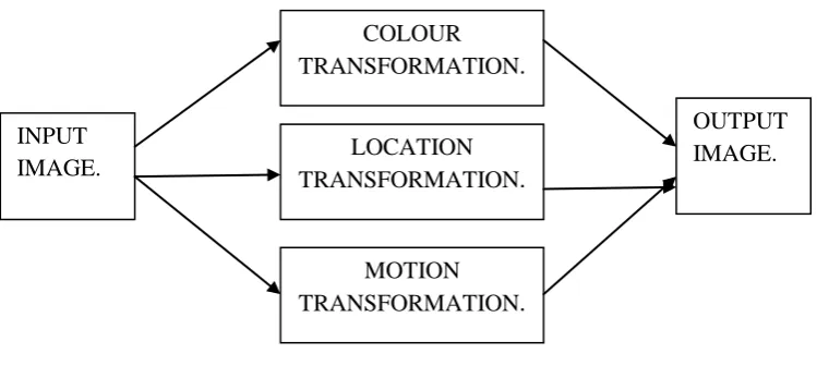
Figure 1: Block diagram of automatic 2D to 3D image conversion system.As shown in Figure 1 for the given 2D query input image, the 3D output is generated which uses the color
transformation, motion transformation and location transformation at each pixel. And finally the outputs of all
this transformations are getting combined to create the final 3D output with depth assigned at each pixel. A
pivotal element in this approach is a point transformation used to compute depth from local low level image
attributes [1].
4.3 Hardware requirement
1. Camera. – In the developed system two cameras are used to capture the input images. Some
specifications of cameras used in the developed system are:
Specification:
1. Image sensor: High quality 1/4 CMOS sensor
2. Effective Pixels:480K pixels ( Interpolated 8M pixels still image & 4M pixels video)
3. Video Resolution: Max. up to 2304 x 1728 pixels – 4MP
4. ImageResolution: Max. up to 3264 x 2448 pixels – 8MP
5. Frame Rate: 30 frames per second.
4.4 MATLAB Function Used In Program
1. Imaqhwinfo - Information about available image acquisition hardware
2. Videoinput - Create video input object
3. Triggerconfig - Configure video input object trigger properties.
4. getdata: Acquired image frames to MATLAB workspace.
5. rgb2gray: Convert RGB image or colour map to gray scale.
6. Size : Array dimensions
7. ycbcr2rgb: Convert YCbCr colour values to RGB colour space.
INPUT
IMAGE.
OUTPUT
IMAGE.
COLOUR
TRANSFORMATION
.
LOCATION
TRANSFORMATION
.
MOTION
442 |
P a g e
8. Disparity : Disparity map between stereo images
9. imshow: Display image
10. Subplot : Create axes in tiled positions
4.5 Algorithm for developed system
1. Start
2. Initialize camera using MATLAB functions to capture query input image.
3. Convert captured raw image into RGB image.
4. Convert captured RGB image into grey image.
5. Get size of image into row and column.
6. Calculate disparity.
7. Calculate cross-covariance.
8. Plot input and output images.
9. End.
Figure 2: output window after camera initialization.
443 |
P a g e
Figure 2 shows the output window after camera initialization. For the conversion of 2D image into 3D image,two images are needed. For capturing two images, two cameras with resolution of 640x480 are used. These two
cameras capture the real time images with maximum accuracy. Figure 2 shows the final output window of the
developed system. When both cameras are properly aligned and captures the highly accurate input images, the
disparity is minimum which produce more accurate 3D output image.
Table 2: comparative chart of performance analysis
Make3D
Karch et al.
Developed system
Value of Cross
Covariance (C)
0.68
0.76
0.59
Value of Cross
Covariance (C)
0.72
0.79
0.69
As shown in the table 2 the value of the cross covariance is different for the different algorithms. The proposed
system achieved nearer value of cross covariance to the systems which are already present in the market.
VI CONCLUSION
The amount of 3D content has greatly increased in recent years and there is more demand for 3D images in
many scenarios. Recovering 3D information from conventional 2D content is an inherently ill-posed problem.
All these reasons make 2D-to-3D image conversion not only valuable in practical applications, but also
meaningful for research.
A single technique to convert the entire class of 2D images to 3D image models does not exist. Combing depth
cues enhances the accuracy of the results of the algorithms. It has been observed that machine learning is a new
and promising research direction in 2D to 3D image conversion. And it is also helpful to explore the alternatives
than to confine ourselves only in the conventional techniques based on depth maps.
2D content to 3D content conversion method which involves human operator in many algorithms are time
consuming but having high efficiency whereas some algorithm which is not involving operator are less time
consuming but having less efficiency. Many algorithms have been developed in the last few years to convert 2D
to 3D images which are complex. Algorithm which uses automatic method for conversion of 2D images to 3D
444 |
P a g e
accuracy and developed system is less complex. The main advantage of this system is its speed is more andefficiency is high.
REFERENCES
[1] Janusz Konrad, Meng Wang, et al, “Learning-Based, Automatic 2D-to-3D Image and Video Conversion”
IEEE Transactions on Image Processing, vol. 22, no. 9, September 2013.
[2]http://iscte.pt/~pjln/MScProposals/MSc-Proposal-PauloNunes-2011-2D-to-3D-Video- Conversion.pdf
[3]Media college,“what is 3D”, a post on MEDIA COLLEGE.com, February 1, 2009 available at:
http://www.mediacollege.com/3d, retrieved on 14/08/2014.
[4] http://www.javelin_tech.com/main/solutions/ going_3d_benefits
[5] Dr. Ir. E. A. Hendricks, Dr. Ir. P. A. Redert “Research Assignment Converting 2D to 3D: A Survey‟‟
Information and Communication Theory Group (ICT), December 2005
[6].Xun Cao, Zheng Li et al, “Semi-Automatic 2D-to-3D Conversion Using Disparity Propagation” IEEE
TRANSACTIONS ON BROADCASTING, VOL. 57, NO. 2, JUNE 2011.
[7] R. Phan, R. Rzeszutek, and D. Androutsos, “Semi-Automatic 2D to 3D Image Conversion Using
Scale-Space Random Walks And A Graph Cuts Based Depth Prior,” In Proc. 13.4th IEEE Int. Conf. Image
Process., September 2011, pp. 3.465–3.463.4.
[8] M. Guttmann, L. Wolf, D. Cohen-Or, “Semi-Automatic Stereo Extraction from Video Footage,” In Proc.
IEEE Int. Conf. Comput. Vis., October 2009, pp. 136–142.
[9]M. Liao, J. Gao et al, “Video Stereolization: Combining motion analysis with user interaction”, IEEE Trans.
Visualization Computer Graph, vol. 18, no. 7, pp. 1079–1088, Jul. 2012.
[10]Chao-Chung Cheng, Chung-Te Li, and Liang-Gee Chen, “A Novel 2D-to-3D Conversion System
Using Edge Information”, IEEE Transactions on Consumer Electronics, Vol. 56, No. 3, August 2010.
AUTHOR
Miss. Anjum R Mujawar completed diploma in Electronics and
Telecommunication and received B.E. in Electronics degree in 2008-2009 and
2011-2012, respectively from Karmaveer Bhaur.ao Patil College of Engineering
And Polytechnique, Satara and presently doing M.E. second year in Electronics from the same college.
Prof. Jalindar D.Nanaware completed M.E Electronics from R.I.T College of
Sakharale and persuing Ph.D. He is associated professor in K.B.P College