Solar Powered Automatic Pattern Design Grass Cutting
1
Robot System using Arduino
2
Dost Muhammad Khan1, Zain Mumtaz 2, Majid Saleem 2, Zeeshan Ilyas 2, Qinglu Ma 3 , Sahrish
3
Ghaffar4 and Saleem Ullah 2,*
4
1 Department of Computer Science & IT, The Islamia University of Bahawalpur, Pakistan 5
2 Department of Computer Science, Khwaja Fareed University of Engineering & Information 6
Technology, Rahim Yar Khan, 64200, Pakistan
7
3School of Traffic and Transportation, Chongqing Jiaotong University, Chongqing, China 8
4 Department of Computer Science, International Islamic University, Islamabad, Pakistan 9
*Correspondence: [email protected]; Tel.:+92-300-7328-198 10
ABSTRACT We present an Arduino-based automatic robotic system which is used for cutting
11
grass or lawns, mostly healthy grass which needs to cut neatly like in a public park or a private
12
garden. The purpose of this proposed project is to design a programmable automatic pattern design
13
grass cutting robot with solar power which no longer requires time-consuming manual
grass-14
cutting, and that can be operated wirelessly using an Android Smartphone via Bluetooth from a
15
safe distance which is capable of cutting the grass in indeed required shapes and patterns; the
16
cutting blade can also be adjusted to maintain the different length of the grass. The main focus was
17
to design a prototype that can work with a little or no Physical user interaction. The proposed work
18
is accomplished by using an Arduino microcontroller, DC geared Motors, IR obstacle detection
19
sensor, motor shield, relay module, DC battery, solar panel, and Bluetooth module. The
grass-20
cutting robot system can be moved to the location in the lawn remotely where the user wants to
21
cut the grass directly or in desired patterns. The user can press the desired pattern button from the
22
mobile application, and the system will start cutting grass in the similar design such as a circle,
23
spiral, rectangle, and continue pattern. Also, with the assistance of sensors positioned at the front
24
of the vehicle, an automatic barrier detection system is introduced to enhance safety measurements
25
to prevent any risks. IR obstacle detector sensors are used to detect obstacles, if any obstacle is
26
found in front of the robot while traveling; it avoids the barrier by taking a right/right turn or stop
27
automatically appropriately, thereby preventing the collision. Also, the main aim of this project is
28
the formation of a grass cutter that relieves the user from mowing their own grasses and reduces
29
environmental and noise pollution. The proposed system is designed as a lab-scale prototype to
30
experimentally validate the efficiency, accuracy, and affordability of the systems. The
31
experimental results prove that the proposed work has all in one capability (Simple and Pattern
32
based grass cutting with mobile-application, obstacle detection), is very easy to use, and can be
33
easily assembled in a simple hardware circuit. We note that the systems proposed can be
34
implemented on a large scale under real conditions in the future, which will be useful in robotics
35
applications and cutting grass in playing grounds such as cricket, football, and hockey, etc.
36
Keywords: android; arduino; bluetooth; grass cutter; sensors; speech recognition
37
1. INTRODUCTION 38
A robot [1] is a machine that can communicate with its physical environment and which can be
39
controlled or programmed electronically to perform specialized tasks. All robots have features of
40
a mechanical and adjustable structure under some form of control, and they mainly have three
41
separated phases: understanding, processing, and action. Commonly, the understandings are done
42
by the sensors mounted on the robot, the onboard micro-controller or processor do processing, and
43
lastly, the operation is performed using motors, engines or with some other actuators. Intelligent
44
robots have a vision [2] and work accurately, using multiple degrees of coordinated action, do
something like a living human, and learn from humans without making mistakes. Robots can be
46
operated by different methods such as some of them can be controlled with gestures [3–6], some
47
with mobile applications [7–9], special remote [10–13] and autonomously [14,15], etc. Grass
48
cutter helps us cutting lawns at length; people can easily manage and beautify their gardens and
49
lawns without any trouble. The grass is a beautiful gift from nature, which helps us to survive in
50
various conditions, and so, the need to lessen their growth is essential to enhance the beauty and
51
attractiveness of our environment. As humankind developed intellectually, grass cutting became
52
an art. Grass cutting tradition starts with the use of hoes, machetes, and cutlasses, and later,
53
advance technology and more reliable techniques of grass cutting were introduced and
54
continuously improved. A robotic lawnmower [16] is an autonomous robot which used to cut grass
55
of lawns or parks, mostly healthy grass which needs to cut neatly like in a private garden or public
56
park. The first lawn mower born in 1830 by Edwin Beard Budding [17], by having an idea from a
57
cloth mill where a cutting barrel machine is used to trim clothes after production for a smooth
58
finish. He noticed that a similar concept might be used to cut grass if the blade can be fixed in the
59
wheel to rotate close to the lawns surface and then he designed a mower primarily to mow the
60
grass on ample gardens and sports ground. In 1867, a scientist introduced an important innovation
61
with a new design of the automatic lawnmower [18] because land roller was removed and replaced
62
by two land wheels on the outside of the structure and this became an instantaneous success with
63
the sold of over 1,000 machines.
64
In the late 1890s, motor-driven mowers arrived as lightweight petrol engines and became
65
available in 1914, invented by “Ideal Power” [1]. Electric powered mowers [19] and rotary grass
66
cutting machines [20] appeared in the era of 1920s to 1930s. An ideal grass cutter robot requires
67
to set up a boundary wire that defines the area of grass to cut in the lawn. Robotic grass cutters are
the second biggest category of domestic manufactured robots used by the end of 2000, and first
69
commercial grass cutter was the “MowBot” [21] that introduced and licensed in 1969 which shows
70
many features of most popular grass movers of today’s. The sales of the latest robotic lawn mower
71
increased about 15 times [22] more than traditional robots in 2012. With the evolution of
72
smartphones, grass cutting robots have integrated with custom apps features to adjust scheduled
73
mowing times, adjustments of the cutter and also manually control the grass cutter. Grass cutters
74
have three types; Walk-Behind Mower [23], Tow-Behind Mower [24], and Riding Mower [25].
75
Walk behind lawn mower are further classified into three types [26] follow as Gas Powered Lawn
76
Mowers, Electric Lawn Mowers, and Manual Reel Lawn Mowers. Rotary grass cutters [27] are
77
manually operated, only spinning the cutting blades are usually powered with internal combustion
78
engines or with an electric motor, having opened sides to discharge cut grasses, and some mowers
79
have a grass collector to store cut grasses. The blade is seldom sharp enough to give an exact
80
cutting point. There have been countless improvements in lawn mower technology in latest years,
81
but with this progress, there are issues with the need to verify the environmental impression of
82
machines.
83
Pollution is human made and can be viewed in our own homes as well as in daily lives.
84
Pollution is the primary concern with the conventional fuel and gas-powered lawn mowers. Riding
85
and Motor-powered push grass cutters have a loud engine, which creates noise pollution and air
86
pollution because of combustion in the engine. Traditional grass cutters are heavy machinery that
87
requires a lot of strength and energy to operate. Along with motor-powered grass mowers,
88
electrical lawn mowers are cannot be easily used in daily lives due to dangerous belts and motors
89
[28], so the dream to cut grass cannot be efficiently fulfilled by the elders, younger, or disabled
90
people. Therefore, human effort is another factor that needs to be reduced. Mowing the grass with
a standard motor is disturbing, and no one takes satisfaction in it due to massive engines
92
combustion, which creates much air pollution and required regular maintenance such as engine oil
93
and greasing. Gas-powered lawn mowers are also not much efficient and responsible for air
94
pollution due to the massive emission of gases, and mainly the price of fuel and gases are
95
increasing rapidly. According to world energy report [29], we gain the energy of around 80% from
96
fossil fuels like oil (36%), coal (23%) and natural gas (21%), 70% of Malaysian home citizens are
97
using fuel-powered to cut grass in daily routine. That time is not far when all energy sources will
98
be consumed so alternative sources can be utilized such as solar energy to avoid an energy crisis
99
in the future. A solar panel [30] contains cells and designed to produce electricity by capturing
100
sunlight and does not make any pollution like fossil fuels and nuclear energy. Solar grass cutting
101
robots are convenient to mow grass and cost-effective because of cordless electric mowers and
102
cutter powered of solar cells that last a long time and have low running costs.
103
A pattern [31] is a regularity in the world, in human-made design, or abstract ideas. As such,
104
the elements of a pattern repeat predictably. Geometric patterns or shapes are generally repeated
105
like a wallpaper design that can be seen directly, but complex patterns in science, mathematics, or
106
any language may be visible only by analysis. Natural patterns include spirals, foams, waves,
107
tiling’s, cracks and those generated by symmetries of rotation but, Observable patterns in nature
108
are disorganized, never exactly repeating. There are many pattern categories, in architecture,
109
designs or visual themes may be merged and repeated to create patterns; a software design pattern
110
in computer science is a solution to programming issues, and in fashion, the pattern is a model
111
used to produce any number of similar garments. In a football or cricket grounds, the fields are
112
beautifully trimmed; the turf is created with perfectly straight green lines of dark and light colors
113
that look painted on the playground. Game spectators may ask how the grounds supervisor creates
such intricate designs, and some of them assume it is done with paint. No matter how complicated
115
or easy patterns are, it should be time-efficient and safe on the grass, but complicated patterns take
116
a little longer, and extra effort is needed to demonstrate that such designs to attract attention.
117
Efficient striping equipment is needed to perform patterns grass cutting such as a reel-type mower
118
or a gardener. Drawing or cutting grass in particular patterns is such a challenging task because
119
due to lack of efficiency and attention of the gardener, the pattern on grass may not have been
120
correctly accurately trimmed.
121
The conventional grass cutting robot has been limited to a particular remote [10–13, 32–35]
122
through the desired actions can only be performed. In this scenario, the robot will lose control if
123
the user lost or broke the remote, leading to hazards, and the user will also waste money. To
124
overcome this remote-control concept, controlling the grass cutting robot by using a Bluetooth
125
Android mobile application along with Arduino is proposed [36–41]. Using the Ultrasonic sensor,
126
the method of identifying the barrier in front of the robot is also proposed [42–49] in which the
127
robot and the cutter stop their motion. In previous literature, most of the grass cutting robots are
128
push mowers controlled with handheld [50–58]. Also, the ZigBee mechanism [59–60] is used to
129
control the movement of the lawnmower. Moreover, an automated grass cutter robot has also been
130
implemented with a Raspberry pie [61–63], and development of grass cutting machine using
131
DFMA (Design for Manufacturing and Assembly) [64–66] is also discussed. A Solar panel system
132
[67–69] is also deployed to make robot energy efficient. Besides these, Specific pattern drawing
133
robots on paper and boards is also accomplished [70–73].
134
Apart from the traditional grass cutting robot system, the term “internet of things” (IOT) [74– 135
77] is also essential for connecting robot with the internet to allow users to control grass cutter
136
from anywhere and anytime. These wireless systems are contributing essential help to robot
regulation systems by utilizing Wi-Fi and cloud computing mechanism etc. As far as we know, no
138
such system is developed that have all in one capability (Android mobile application with touch
139
and voice recognition system, solar powered, monitoring the obstacles, cutting grass in special
140
patterns). So, a need still exists for the design of solar powered automatic pattern design grass
141
cutting robot system that supports various tasks (e.g., android mobile application control and voice
142
recognition concepts, obstacle detection and patterns cutting) and very easy to use and can be
143
easily assembled in a simple hardware circuit.
144
In this paper, we introduce the design and experimentally demonstrate that a grass cutting
145
robot system can be controlled by just a click on the cellphone with an Android operating system,
146
and voice recognition via Bluetooth technology which reduces human effort so that elderly users
147
and disabled persons can fulfill their tasks by themselves, and there is no need for gas, oil, and
148
engine to use this device because it is solar powered. This prototype is user-friendly, cost-effective,
149
secure and eco-friendly; with its control capability, the grass cutter robot will stay within the
150
boundaries of the lawn because the user can have control over the lawn mower with the controller
151
and the working range is also increased due to the absence of main supply wires. The user can trim
152
the grass with different length because the cutter is fully adjustable.
153
This work is achieved with the proper arrangements of the Arduino Uno microcontroller, solar
154
panel, IR obstacle detection sensor, simple DC motors, geared DC motors, android
mobile-155
application, Bluetooth module, and relay module, where motors are connected to gear motor drives
156
so that less speed and more power can be attained. The robot is dual powered with a Hybrid Solar
157
panel & a Lithium-Ion rechargeable battery which provides power supply to the Circuit, Motors,
158
etc. When sufficient sunlight is falling on the Solar panel, the robot runs on Solar Power, and
159
whenever there is no light or low intensity of sunlight, the robot runs on Battery power. The battery
is also recharged when the robot is in Light, thereby avoiding the robot from frequent recharging
161
and provides an uninterrupted power. There are two main controllers in android the application.
162
The first one is the touch buttons in which the robot will move accordingly as the user touches the
163
button and the second one is voice recognition in which the grass cutting robot will follow and
164
move accordingly as the user says the operating command. Most importantly, the mower will mow
165
grass in patterns accordingly as the user pressed pattern button and an obstacle detection sensor is
166
set to detect the obstacle in front of it, and when a sensor detects the barrier, it stops moving, and
167
the cutter will be turned off. Hence, the proposed systems of controlling the grass cutting robot
168
with android application control and voice recognition are performed and displayed in a lab-scale
169
prototype to confirm that the proposed designs can be easily implemented in large and real-scale
170
conditions in the future.
171
The innovative component of the proposed work in this system is an Arduino that is a
user-172
friendly microcontroller that can be readily available. On the other hand, automated grass cutting
173
systems can be designed with raspberry pie, ZigBee, and other microcontrollers that are costly and
174
complicated for the process to unite the various functionalities in a single hardware circuit.
175
Furthermore, the motivation for conducting this research is to facilitate the old-age and physically
176
disabled people to cut grass which cannot walk and also make patterns on grass easily without
177
difficulty.
178
The remaining content of the paper is ordered as follows. In Section 2, the idea of the
179
automatic pattern design grass cutting robot car is introduced with a detailed explanation of the
180
electronic components that are used in the proposed system, based on an android mobile
181
application. More, the experimental results of a lab scale production model are shown in Section
182
3, and the conclusion is given in Section 4. Lastly, Section 5 presents future work.
184
185
2. MATERIALS AND METHODS 186
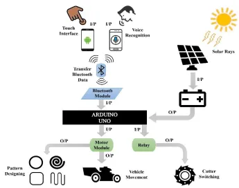
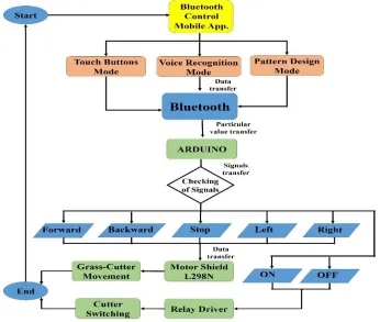
For the simplicity of analysis, Figure 1 demonstrates the complete working mechanism and the
187
features of the proposed automatic robot car whereas I/P and O/P represent the flow of the system
188
as input and output. There are two modes of transmission and controlling of the grass cutter. The
189
first one is the arrow touch buttons with an android mobile application, which is specially designed
190
for Android mobile and available and can be easily downloaded [77]. In this system, when the user
191
presses the corresponding touch button, a signal is transferred to the Arduino UNO that is attached
192
to the car through the built-in mobile Bluetooth device. After receiving the following signal
193
command, Arduino will check this signal with a predefined instruction that is programmed via
194
coding and send the following signal to the motor module to move the wheels of the robot, make
195
grass pattern, or relay to turn ON/OFF Cutter accordingly to the received signal. The second mode
196
is to control a robot car with a Voice recognition system with the Android application. In this
197
system, when the user speaks the corresponding keyword, the google voice recognition system
198
recognizes the spoken keyword and send it Arduino UNO, after receiving the following command,
199
Arduino will check this keyword with a predefined keywords that are already programmed for
200
movement of grass cutter. If the keyword matches with predefined, the corresponding signal is
201
sent to the motor module to move the grass cutter, or to relay for switching of the cutter. Also,
202
Solar panel will charge the battery with solar rays to reduce the consumption of electricity.
204
Figure 1. The architecture design of pattern design grass-cutter controlling with touch
205
buttons and voice recognition of mobile application.
206
2.1. Electronic Components 207
Various electronic components are used for creating electronic circuits. Consequently, our
208
proposed circuit diagrams also contain those components that are specified in Table 1.
209
Table 1. Specification of electronic components used in to design the proposed system.
210
Components Specifications
Arduino UNO [78,79] 28 pins; Operating voltage: 7–12V
Bluetooth Module HC-05 [80]
6 pins; Operating voltage: 3.3–5V; Transmission
L298N Motor Module [81] Operating voltage: 5V; Max power: 25W
IR Obstacle Detection Sensor
[82]
Voltage: DC 3–5V; Range 2–30 cm; Angle: 35o
Geared DC Motor with
Encoder [83] / Simple DC
Motor [84,85]
Geared Motor (6 Wires; Operating voltage: 12V;
Speed: 600 rpm), Simple Motor (2 pins, Operating
voltage: 12V; Speed: 46000)
DC Battery [86]
Input Voltage: 12V; Capacity: 7A; Battery type:
Rechargeable
Solar Panel [87] Operating Voltage: 12V; Max. Power:5W
Relay Module[88] Pins: 6; Operating Voltage: 5V DC
Android Mobile Application
[77]
Android compatible
2.1.1. Arduino UNO 211
The Arduino Uno microcontroller board [78,79] is generally based on the ATmega328
212
microcontroller’s series and has a desktop, and web IDE (integrated development environment) to
213
write, compile and uploads the programming languages codes to memory. Different sensors
214
forward the observed data as an input to the microcontroller and send output to different devices
215
such as motors, LED, relay module, etc. It contains a total of 28 pins from which 14 digital
216
input/output pins (six are PWM pins (pulse width modulation)) and six are analogs pins which
217
used for interaction with the electronic components like LDR sensor, ultrasonic sensors, etc., 3
218
pins for grounding and other pins for 5V, 3.3V, VIN, RESET and AREF (analogue reference).
Arduino microcontroller have 32 KB of storage memory, 2 KB storage of SRAM (static
random-220
access memory) and only 1 KB of EEPROM (electrically erasable programmable read-only
221
memory). Arduino principally supports C/C++ programming language compiler (supports other
222
languages like Python, java through libraries), macro-assemblers, and evaluation kits. Additionally,
223
it has a USB connection jack for connecting with computer, a jack for external power supply, 16
224
MHz ceramic resonators an ICSP (in-circuit serial programmer) header, a reset button to reset to
225
factory setting. Its operating voltage is 7 to 12V with a limit up to 20V.
226
2.1.2. Bluetooth Module HC-05 227
The HC-05 [80] Bluetooth module is designed for personal wireless serial connectivity and used
228
in a Master or Slave configuration, providing it with an excellent solution for wireless
229
communication. This serial port Bluetooth module is fully adequate Bluetooth V2.0 + EDR 3 Mbps
230
Modulation with 2.4 GHz radio transceiver and baseband. It contains total six pins; ENABLE pin
231
to toggle within AT and Data command mode, VCC pin for giving voltage, Ground pin,
TX-232
Transmitter and RX-receiver for sending and receiving serial data and lastly, a State pin for
233
checking of Bluetooth pairing/un-pairing). Its operating voltage is 3.3–5V and transmitting range
234
is up to 90 m.
235
2.1.3. L298N Motor Module 236
An L298N dual H-bridge motor [81] controller is used to manage the direction and speed of one
237
or two DC (direct currents) motors of up to 2A current each with a voltage between 5V to 35V. It
238
has basically four input pins to receive the signal from the microcontroller and four output pins for
239
the connection of the DC motors, two EN jumpers (Enable pins control the speed of DC motors).
240
It has a built-in 5V regulator which is removed when the supply voltage is up to 12V.
2.1.4. IR Obstacle Avoidance Sensor 242
An IR obstacle detection sensor [82] is a heat sensitive sensor used for the detection of an obstacle.
243
It consists of an infrared transmitter, receiver and a potentiometer for distance adjustment. When
244
an object crosses in front of it, the emitted rays collide with the surface of an obstacle and reflect
245
to the receiver, and it will recognize this a motion.
246
2.1.5. Geared DC Motor with Encoder / Simple DC Motor 247
An encoder [83] provides an electrical signal that is used to control speed and position. It turns the
248
mechanical signal into an electrical which is managed by the control system to control special
249
parameters of the application and make corrections if necessary. These parameters are defined by
250
the type of application, which includes RPM, distance, speed, position between others. Cylindrical
251
geared motor have six pins; Encoder A phase and B phase, Motor power supply Negative and
252
Passive, Encoder power supply Negative and Passive.
253
A simple DC motor [84,85] converts electrical energy into mechanical and have four basic
254
types that are series-wound, shunt-wound, compound-wound, and permanent magnet motors. A
255
DC motor contains an armature, a stator, a rotor and a commutator with brushes. The opposite
256
polarity within the two magnetic fields of the motor causes it to run. DC motor is the most common
257
type of motor used in many household appliances, such as cooling fans and shaving machines, etc.
258
It have only two wire; one for 12V VCC and the other one is for grounding.
259
2.1.6. DC Battery 260
A battery [86] transforms chemical energy into electrically a chemical reaction that is kept inside
261
the battery and used to power other components such as bulb, fan, etc. A battery provides direct
current (DC) electricity (electricity that flows only in one way and does not reflect). When a battery
263
is giving electric power, red is for supplying DC voltage, and black is for grounding.
264
2.1.7. Solar Panel 265
Solar panels [87] absorb sun rays energy to generate DC electricity, and this electricity is supplied
266
to the battery via regulator which assures the battery is charging correctly and not damaged.
267
Photovoltaic modules contain the cells that absorb the solar rays, and that generates and provides
268
solar electricity. AC appliances first need an inverter to convert the DC electricity into AC
220-269
240V, but DC appliances can be powered from the battery directly.
270
2.1.8. DC Relay Module 271
Relay Driver (RD-1) is a totally programmable one channel logic controller is used to manage
272
solid or mechanical state relays in DC and AC voltage power systems. It mainly works as a switch
273
for electronics for on and off. It has 6 pins; VCC, GND, Input pin, normally open, normally closed
274
and common pin.
275
2.1.9. Android Mobile Application 276
An Android mobile application is an application software developed in a computer programming
277
language (C, C++, Java, etc.) which run on the Android platform. The application for controlling
278
the grass cutting robot system is available [77] and can be easily downloadable.
279
3. DESIGNING METHODOLOGY 280
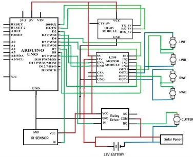
Figure 2 shows the circuit design of the grass cutter system, which is control by an android mobile
281
application using Bluetooth. In this scenario, the robotic grass cutting system will move in the
282
same direction as the user presses the arrow touch button or speaks the corresponding keyword. In
this task, one Arduino UNO, an HC-05 Bluetooth module, an L298N motor module, IR obstacle
284
detection sensor, geared DC motor with encoder, simple DC motor, DC battery, solar panel, and a
285
relay module were used. The RX pin of the HC-05 module is attached to the Arduino PIN D0/RX,
286
TX to the D1/TX, Ground pin to the GND and VCC (voltage at the common collector) pin to the
287
5V pin of the Arduino. IN pin of the IR obstacle detector sensor is attached to the Arduino PIN
288
D2, VCC pin to 5V and ground pin to GND port, as shown in Figure 2. ENA and ENB pins of
289
L292N motor module are connected to the digital pins A3, A6; IN1-4 pins to Arduino Pin 4, 5, 7,
290
8; 5V and GND pin to Arduino 5V and GND pins, 12V pins to Battery positive terminal.
291
Further, OUT1 pin is attached to the negative terminals of LWF (Left wheel front) and LWB
292
(Left wheel back), OUT2 pin of the motor module is connected to the positive terminals of the
293
LWF and LWB motors. Similarly, OUT3 of the motor module is connected to negative terminals
294
of RWF (Right wheel front) and RWB (Right wheel back), and OUT4 is connected to positive
295
terminals of RWF and RWB. In this way, VCC, GND and IN terminal of relay driver is connected
296
to Arduino 5V, GND and digital pin D9 and at last, NO (Normally open ) pin to the positive
297
terminal of Cutter, COM pin to the positive terminal of the battery and negative terminal of Cutter
298
to negative terminal of battery. Positive and negative terminals of the solar panel are connected to
299
+VE and –VE terminals of the battery. The complete software code of this case is presented in
300
Figure S1 of the supplementary materials.
301
3.1. Movement of Motors with Mobile Application 302
As the user presses the touch arrow buttons or speaks the keywords, the mobile application will
303
recognize that keywords and a signal is sent to the Arduino. There are genuinely seven values:
304
Forward, Backward, Left, Right, Stop, OFF and ON for each function of the grass cutter. In simple
305
words, the set of keywords are defined for the movement of the grass cutter in a specific way. If
the received data by the application lies within these specified values, then the corresponding
307
decision will be made. This decision value will be sent to the microcontroller, which then processes
308
it to understand the keyword, and it will send a signal to move the robotic grass cutter accordingly.
309
310
Figure 2. The circuit design of pattern design grass cutter controlling system with
311
Android mobile application using Bluetooth.
312
There is a total of two DC geared motors and three simple DC motors; Both geared motors
313
(600 RPM) for left back wheel, and for the right back wheel, two simple DC motors (400 RPM)
314
for the left front wheel and right front wheel, and third simple DC motor (46000 RPM) for the
315
blade (cutter) is used in the construction of this grass cutter. The motors are controlled by the
316
L298D motor shield and relay driver.
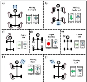
Figure 3 represents the main idea of Bluetooth communication and motors movement. When
318
the user presses the upward touch arrow button or speaks the Forward keyword in voice
319
recognition mode, it is recognized as the forward movement, all the four wheels of motors will
320
rotate forward and the grass cutter will move in the forward direction which can be easily seen in
321
the Figure 3a. Figure 3b illustrates the case when the user presses the downward touch arrow button
322
or speaks the “Backward” keyword in voice recognition mode, the signal is recognized as the move
323
backward, and all the four wheels of motors will rotate backward, and the grass cutting robot
324
moves in the backward direction. In Figure 3c, the user pressed the ON touch button or spoke ON
325
keyword in voice recognition mode, the signal is recognized as to switch ON the cutter, and none
326
of the wheels of motors will rotate, only cutter motor will rotate. When the user presses the Red
327
touch button or speaks the Stop keywords in voice recognition mode, the signal is recognized as
328
to stop the car; all the four wheels will stop moving as shown in Figure 3d. When the user pressed
329
the OFF touch button or spoke OFF keyword in voice recognition mode, the signal is recognized
330
as the turn OFF the cutter, and the cutter motor will stop rotating as illustrated in Figure 3e. In
331
Figure 3f, when the user pressed the Right arrow touch button or spoke Right keyword in voice
332
recognition mode, the signal is recognized as to turn Right, left diagonal motors (front left and
333
back left motors) will rotate forward, and the grass cutter moves in the right direction. Similarly,
334
when the user pressed the Left arrow touch button or spoke Left keyword in voice recognition
335
mode, the signal is recognized as the Left turn, so the right diagonal motors (front right and back
336
right motors) will rotate forward and the grass cutter will moves in the left direction, as represented
337
in Figure 3g.
338
The values of an each signal will never lie within the two keywords (the values for each action
339
is defined differently from another step), i.e., the value of turn right will not lie in the values of
two directions (left turn and forward, left turn and backward, right turn and forward, right turn and
341
backward).
342
343
Figure 3. The theme of Android Application (i.e., Working of Android application,
344
motors, and cutter): (a) Vehicle moving forward with arrow and voice recognition system;
345
(b) Moving backward; (c) Cutter ON; (d) Vehicle stopped; (e) Cutter OFF; (f) Moving to
346
right; (g) Moving to left.
347
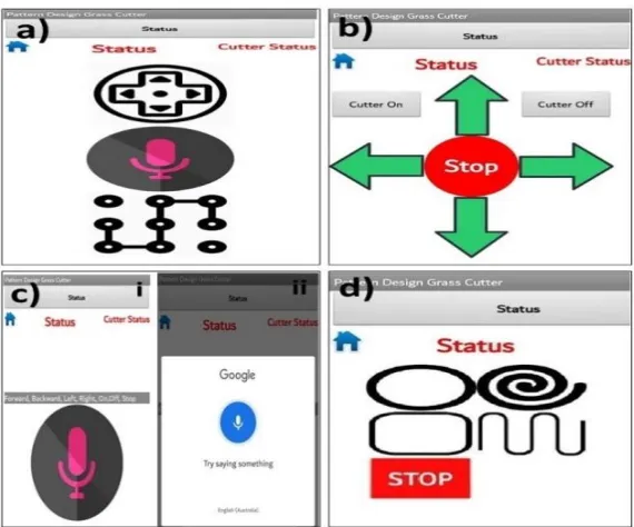
3.2. Android Mobile Application 348
MIT App Inventor [89] is a visual programming drag and drops platform for designing and
349
development of fully functional android mobile application. App Inventor’s user interface is
350
consists of two parts: a Designer for selecting the components of the app and a BlocksEditor for
351
setting the operations and working for the application. App Inventor’s building blocks are simple
352
user interface contains elements such as buttons, labels, list pickers, images, etc., linked with the
mobile device’s features (Bluetooth, texting, NFC, GPS, etc.) Therefore, the fundamental
354
structures of this drag and drop enabled app developer to efficiently manage the functionalities of
355
this portable, touch-enabled sensing devices. By concentrating on the device’s services, App
356
Inventor presents an automatic programming metaphor. A Texting component is used for an
357
application that sends and receives texts. The block for identifying an incoming text is
358
“Texting.MessageReceived”. This understandable, action based, drag and drop, event-driven,
359
programming model reduces the difficulty level that usually experienced in traditional text-based
360
programming environments. In our application, we have used Bluetooth client component, Speech
361
recognition component, Notifier component, Text to speech component, button component, label,
362
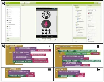
and title components. Figure 4a shows the main designer view of the MIT application development
363
platform includes the user interface menu, viewer, components menu, and properties menu. In
364
Figure 4b, the blocks for all the components are shown, such as in screen 1, Bluetooth components
365
blocks having Bluetooth connection, show alert notifier, label component and speak message
366
components as shown in Figure 4b i . In Figure 4b ii, the blocks for speech recognition page is
367
shown having a speech recognition component, send text, and speak message components. In
368
Figure 4b iii, the blocks for pattern one buttons is illustrated having sent text component and label
369
component which will send “I” when the button is pressed and set a label to forwarding. The blocks
370
for UP button is shown in Figure 4b iv, in which the send text component and label component is
371
used which will send “A” if the user pressed the button and set a label to forwarding.
373
Figure 4. Design view and Blocks editor of Android Application for pattern design grass
374
cutter. (a) Design view window. (b) i. Bluetooth module component. ii. Speech
375
recognition component. iii. Send text component for the pattern. iv. Send text component
376
for up arrow button.
377
There are total three ways to move grass cutter; Touch arrows buttons, voice recognition, and
378
Pattern cutting as shown in Figure 5a which is the home page for the Android application also
379
having a status bar for displaying the status of Bluetooth connectivity and status view for wheels
380
and cutter. In Figure 5b, there are a total of 8 buttons; forward, backward, stop, left and right for
381
wheels movement, Cutter ON and OFF for switching of cutter, home button for navigating back
382
to home page of application and also having a status view for wheels and cutter whose value will
383
be changed accordingly to the button pressed by user.
385
Figure 5. Design view and Blocks editor of Android Application for pattern design grass
386
cutter. (a) The homepage of an android application showing three different option of grass
387
cutter control. (b) Touch arrow buttons interface for controlling grass cutter. (c) Voice
388
recognition mode; i. The window of voice recognition before the button press. ii. Voice
389
recognition window after the button pressed. (d) Pattern designing interface having four
390
different patterns.
391
For example if the user press forward arrow button, the “Status” text will be change to
392
“Forward” text or if user press Cutter ON button, “Cutter Status” text will be change to “Cutter
393
ON” and this will mechanism will work correspondingly for all buttons. In this way, figure 5c
394
represents voice recognition interface where Figure 5c i is the starting screen where the user
395
presses the voice recognition button to open a new sub-window to speak the keyword which is
396
illustrated in Figure 5c ii. Figure 5d represented with a screen of having four patterns buttons such
397
as “circle, spiral, rectangle, and continue” shapes cutting, and a status bar for displaying
398
corresponding text. The method to operate the grass cutting system via an android system is as
follows: Firstly, download [77] and install the app on the mobile phone. Turn on the mobile’s 400
Bluetooth, run the application. Here, make sure that the Bluetooth of grass cutter is switched on,
401
select connect to the HC-05 to authenticate the pairing (pairing password is 1234 or 0000). Finally,
402
click on the arrows touch buttons or microphone symbol on the voice recognition interface and
403
give the voice commands. If the user speaks anything, given command will convert into text. As
404
the phone is connected to the microcontroller using a Bluetooth module. After the conversion of
405
the voice command into the text, the app will send the necessary data to the microcontroller using
406
Bluetooth of the phone. According to the command, the grass cutter will move forward, backward,
407
stop, right, left, cutter ON, and cutter OFF.
408
3.3. Pattern Design Mechanism 409
To successfully achieve the desired pattern, we will use the motor and wheels movement technique
410
to generate a pattern cutting on the grass. There are mainly four different types of design that our
411
system can create on the lawn, such as circle, spiral, rectangular, and continue shape. Wheels
412
movement is controlled with programming to move in a special position and direction to generate
413
these patterns. To generate a circle pattern, we only programmed left diagonal motors to rotate in
414
full speed for the fixed time accordingly to circle diameter, while right diagonal will move freely
415
so that the grass cutter will move in a right circle position and the cutter will cut the grass in the
416
desired circle shape.
417
digitalWrite(LeftMotors_P, HIGH); (1)
digitalWrite(LeftMotors_N, LOW);
analogWrite(SpeeDControl, 255);
digitalWrite(RightMotors_N, LOW);
analogWrite(SpeeDControl, 0);
digitalWrite(Cutter, HIGH);
Delay(5000);
In Programming Equation 1, left diagonals motor are high and given maximum speed (0
418
means no speed, and 255 maximum means speed), Cutter is HIGH, and the delay given is 5000
419
milliseconds (time required for a 2 feet diameter circle is carefully calculated). So, the left diagonal
420
motors of grass cutter will move in full speed for 5 seconds to generate a circle shape pattern on
421
grass. To generate a spiral pattern, we programmed left diagonal motors to rotate in full speed and
422
right diagonal motors in speed incrementing loop for the fixed time accordingly to spiral diameter,
423
so that the grass cutter will move and the cutter will cut the grass in the desired spiral shape.
424
425
digitalWrite(LeftMotors_P,HIGH); (2)
426
digitalWrite(LeftMotors_N, LOW);
427
analogWrite(SpeeDControl, 255);
428
digitalWrite(RightMotors_P, HIGH);
429
digitalWrite(RightMotors_N, LOW);
430
for (int i = 0; i <= 20; i++) {
431
analogWrite(SpeeDControl, i);
432
digitalWrite(Cutter, HIGH);
433
delay(50); }
434
delay(10000);
435
In Programming Equation 2, left diagonals motor are high with maximum speed, and right
437
diagonals motors are also high but initially have 0 speed with incrementing loop to 20 (each
438
increment have a delay of 50 milliseconds) and grass cutter will move for 10000 milliseconds
439
(time required for a 5 feet diameter spiral that is carefully calculated). So, the grass cutter will
440
move for 10 seconds to generate a spiral shape pattern on grass. Similarly, to create a rectangle
441
pattern, firstly we programmed all wheel motors to rotate for 3 seconds to go straight, then only
442
left diagonal motors will rotate for 1 second to take a right turn, and this mechanism will run three
443
times more, so that the grass cutter will cut the grass in the desired rectangular shape. Lastly, we
444
programmed all wheel motors to rotate for 3 seconds to go straight, then only left diagonal motors
445
will rotate for 2 seconds to take a right U-turn, again all wheel motors to rotate for 3 seconds to go
446
straight and then only right diagonal motors will rotate for 2 seconds to take a left U-turn, and this
447
mechanism will run two times more (programming for all patterns are presented in supplementary
448
material file) and in this way the grass cutter will cut the grass in the desired Continue pattern
449
shape.
450
3.4. Results and Discussions 451
In the beginning, the Android mobile application provides three modes (touch button, voice
452
recognition, and pattern design) of controlling grass cutter, as illustrated in Figure 6. Firstly,
453
connect the Android mobile application with Arduino by the Bluetooth module, when the user
454
presses any touched button or speaks some keyword in voice recognition in the app, it will
455
consequently transfer the data to Arduino that is placed on grass cutter via Bluetooth module. After
456
receiving the data, Arduino will measure these with predefined Keywords.
458
Figure 6. The flow diagram of the Android application based grass cutter control
459
system.
460
Arduino Uno will check if the user speaks or press “Forward” touch button, it will send a
461
forward signal to the motor shield. If Arduino founds that user press the backward or speaks a
462
backward keyword, it will send a back message to the motor shield. Similarly, if the user pressed
463
the right arrow or speak Right, Arduino will send a Right signal to the motor shield. Furthermore,
464
if keywords are recognized as left move if user press left arrow or speaks left, Arduino will send a
465
Left signal to motor shield, and if user press stop button or speaks stop, Arduino will send a stop
466
signal to the motor shield. Thus, after obtaining the signal, the motor module will check and control
467
the grass cutter’s movement. Similarly, If Arduino found that user speaks or press the ON/OFF
468
touch button, it will send a signal to the relay module to turn ON or OFF cutter. Furthermore, It
Arduino founds that the user pressed any patterns button; it will send a signal to the motor module
470
to move in corresponding patterns and relay module to turn on the cutter.
471
Initially, the grass cutter robot will not move and stayed motionless when it does not receive
472
any signal from an android application. Whenever the user pressed or speaks the keyword, the
473
signal will be measured of that direction by an Arduino and command will send to the motor shield
474
to turn on corresponding motors and the grass cutter robot will start moving in the similar to the
475
keyword.
476
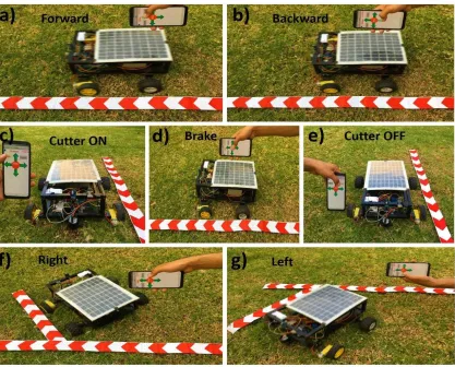
Figure 7 shows the final presentation of the proposed pattern design grass cutting robotic
477
system that controlled via touch arrows buttons of android application. Figure 7a represents that
478
the grass cutter is moving to the forward direction (all the four wheels is moving) because the user
479
pressed the Up arrow button on the android application. In Figure 7b, the grass cutter is moving in
480
a backward direction as the user pressed the Down arrow button. The cutter is working because
481
the user pressed the Cutter ON button, as illustrated in Figure 7c. In Figure 7d, the grass cutter is
482
not moving because the user presses the stop button (brake command). In Figure 7e, the cutter is
483
not working as the user pressed Cutter OFF button. The grass cutter is moving in the right direction
484
because the user pressed the right arrow button in the android application, which is seen in Figure
485
7f. Similarly, in Figure 7g, the grass cutter is moving to the left direction because the user pressed
486
the left arrow button.
488
Figure 7. Result diagrams of the automatic pattern design grass cutting robot system
489
using touch arrows button. (a) The up arrow button is pressed, so the grass cutter is
490
moving forward. (b) The down arrow button is pressed, so the grass cutter is moving
491
backward. (c) The cutter is working when Cutter off button is touched. (d) The grass
492
cutter is not running as the stop button is pressed (e) the cutter is not working when the
493
cutter OFF button is pressed. (f) The right arrow button is pressed, so the grass cutter is
494
moving to Right direction. (g) The grass cutter is moving to left as the Left arrow button
495
is pressed.
496
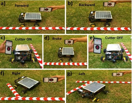
Moreover, mobile-application for voice recognition is also used, and the voice recognition
497
module in the system is limited mainly to the seven voice commands such as Forward, Backward,
Stop, Right, Left, Stop, Cutter ON and OFF. This voice recognition system uses google speech to
499
text [90] to recognize and process the human voice. Figure 8 shows the result diagrams of the
500
proposed pattern design grass cutting robot system that is controlled via voice recognition through
501
a Bluetooth mobile-application. In this process, Figure 8a represents that the grass cutter is moving
502
to forward direction after recognition of voice because the user inputs the forward move voice
503
command to the mobile application. Similarly, the car is moving in a backward direction after
504
voice recognition because the user inputs the backward move voice command, as seen in Figure
505
8b. In Figure 8c, the cutter is moving because the user inputs the Cutter ON voice command.
506
Meanwhile in Figure 8d, the user input the Stop voice command to the application, the grass cutter
507
is not moving. The cutter is not moving because the user inputs the Cutter OFF voice command,
508
as seen in Figure 8e. On the other hand, in Figure 8f, the grass cutter is moving in the right direction
509
after recognition of voice because the user inputs the right voice command. Similarly, the grass
510
cutter is moving to left direction after recognition of voice because of user inputs the left voice
511
command, can be viewed in Figure 8g.
513
Figure 8. Results diagrams of the automatic pattern design grass cutting robot controlled
514
with voice recognition of mobile- application. (a) Grass cutter is moving forward because
515
the voice is recognized as a forward command (b) The grass cutter is moving reversely
516
as the voice is identified as a backward command. (c) The cutter is working because the
517
voice is recognized as Cutter ON. (d) The grass cutter is not moving (stopped) because
518
the voice is recognized as a Stop. (e) The cutter is not working because the voice is
519
recognized as Cutter OFF. (f) The car is moving in the right direction as the voice is
520
identified as a right move command. (g) The voice is recognized as a left command, so
521
the car is moving to left direction.
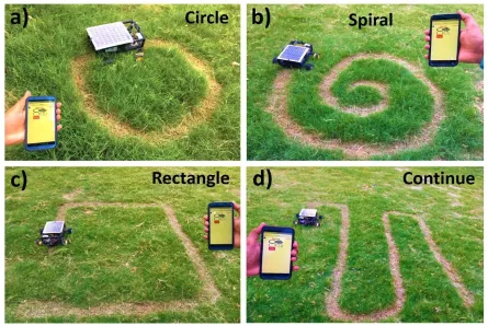
Figure 9 presents the final demonstration of the proposed grass cutting robotic system with
523
four different types of pattern designing on the grass. Figure 9a represents that the grass cutter is
524
moving and cutting grass in circle shape because the user pressed the “circle” pattern button on
525
the android application. In Figure 9b, the grass cutter is moving and cutting grass in a spiral shape
526
as the user pressed the “spiral” pattern button. The user pressed the “continue” pattern button, so
527
the grass cutter is moving and cutting grass in continue shape, as illustrated in Figure 9c. Similarly,
528
in Figure 9d, the grass cutter is moving and cutting grass in rectangle shape because the user
529
presses the “rectangle” pattern button.
530
531
Figure 9. Results diagrams of the automatic pattern design grass cutting robot controlled
532
with mobile- application. (a) Grass cutter is mowing grass in circle shape as user pressed
533
“pattern 1” button. (b) Grass cutter is cutting grass in circle shape after getting command
from mobile. (c) Grass cutter is cutting grass in continue shape. (d) Grass cutter is cutting
535
grass in rectangle shape.
536
We used the Arduino-based control systems with wireless connectivity, in which the pattern
537
design grass cutting robot system could be automatically controlled based on Android application
538
(touch buttons and voice recognition), to avoid any limitations of the specifications, wireless range,
539
etc. In some cases, we required wireless connectivity (WI-FI module) to make the system more
540
scalable for easy integration of new devices. Wi-Fi module could be replaced with the Bluetooth
541
module to extend the wireless range for this system further. Besides, the described systems are
542
presented as lab-scale prototypes, to improve safety measurements, the obstacle detection feature
543
can make it possible for the full-scale facilities and can also be managed by applying other
544
technologies like camera [91].
545
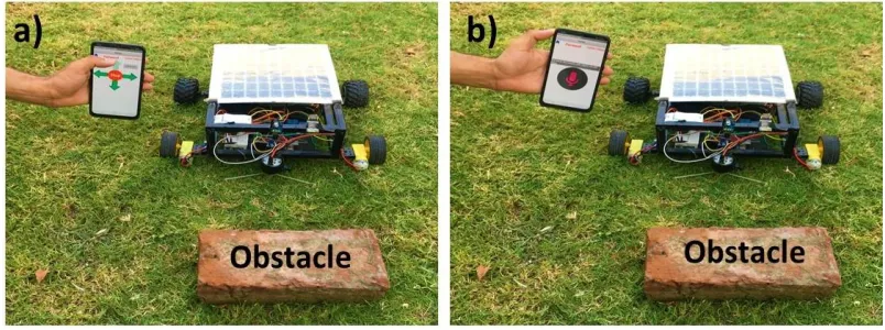
It is worth noting we should consider the cases when the grass cutting robot collides with any
546
obstacle in front of it while moving with mobile-application. Thus, for improving the safety
547
measurements, we proposed a system to avoid the grass cutter from a collision with an obstacle by
548
the help of sensor (the car will stop before the obstacle) as illustrated in Figure 10. In Figure 10a,
549
the grass cutter is not moving to forward direction, whereas the Up arrow button is pressed.
550
Similarly, the grass cutter is not moving to forward direction, although the user speaks the forward
551
keyword in mobile-app because the sensor senses that there is an obstacle in front of the car as
552
seen in Figure 10b.
554
Figure 10. Avoidance of grass cutting robot system from obstacles using android
555
mobile application; (a) Touch arrow buttons (b). Voice recognition system.
556
The effectiveness of the proposed mobile-application technique has much effective for
557
different purposes such as, in the grass cutting field it can be used by disabled patients to cut simple
558
grass or in different complex patterns easily just pressing a single button on the mobile application.
559
4. CONCLUSIONS 560
In this article, a design scheme for android mobile application system for controlling a pattern
561
design grass cutting robot having solar energy capability based on Arduino has been explained,
562
which is programmed to respond to events (based on the touch arrow buttons, voice recognition
563
and pattern designing with Android mobile application as described above) and to make
564
corresponding actions. The proposed project presented with mainly three operational modes in
565
which the system is using a mechanism of controlling the grass cutting robot based on touch arrow
566
buttons (grass cutter moves similarly to the direction of the button presses) and a voice recognition
567
system( grass cutter moves accordingly to the keyword spoken by the user). This system is further
568
expanded into composing the different complex patterns on the grass with touch buttons on
569
mobile-application. Meanwhile, it is presented that the proposed systems have capabilities to
identify the obstacles in front of the grass cutting robot. The hardware implementations of the
571
proposed systems are provided at a lab-scale model to prove the simplicity, dependability, integrity,
572
adaptability, and inexpensiveness of the system. As a lesson learned, we confirm that the
573
introduced systems can be easily implemented under real conditions at great-scale in the future.
574
Meanwhile, the proposed pattern design grass cutting robot system have the advantages such
575
as user-friendly, low-power consumption, low-cost approach, easy to use, simple and the system
576
is less in size, so the little space is needed to adjust in hardware circuits. Besides, the proposed
577
prototype is highly robust against unforeseen problems and can be easily extended further in the
578
hardware section, and multiple applications can be attached to reduce the personal effort of
579
upgrading. Similarly, voice commands are sent and received wirelessly with the help of Bluetooth
580
technology but on the other hand, Bluetooth technology have only ranged up to 10–15 m only, the
581
distance of processing in the system is less. If the Bluetooth connection gets dropped frequently,
582
it will cause much delay or loss in the transmission and reply of commands. Further, the number
583
of errors will increase in the presented voice-recognition system, if there is any background noise
584
or other sounds in the surroundings. A limited number of patterns are manifested here, but the
585
algorithm can be extended in several ways, and more patterns can be added into the system.
586
587
588
5. FUTURE WORK 589
This project is completed with the available sources, and the results are good enough but are not
590
up to the expectations. Future work will build upon the improvement of the recognition system to
591
increase accuracy and more patterns. Efficiency in pattern design grass cutting can be improved
592
by using some other mechanism such as using the compass to fix angles of patterns or with an
array of the programmed matrix. Speed of motor is decreased due to the usage of heavy materials,
594
so the more speed of motors can be achieved by using lightweight material and battery.
Geo-595
Fencing technology [92] can make grass cutter more capable of tackling complex boundary shapes
596
with higher precision, and Boundary area can be calculated more accurate by more complex
597
algorithm, so the time and energy required can be easily maintained and can mow multiple gardens
598
in the same session by traveling to the next lawn automatically using satellite tracking. GPS can
599
be added to the proposed grass cutting system to track its location. GSM module can be used to
600
make capable of sending and receiving messages from the user’s mobile phone through SMS if
601
someone does not have an android mobile. By utilizing Wi-Fi, the communication range can be
602
increased by installing routers, and a wireless camera can be used which will provide live
603
streaming and can be used for controlling the grass cutter from faraway places.
604
Supplementary Materials: The following are available online at www.mdpi.com/xxx/s1, Figure
605
S1: The circuit design of solar powered automatic pattern design grass cutting robot system using
606
Arduino.
607
Author Contributions: All of the authors contributed in literature search, figures, study design,
608
data collection, data analysis, data interpretation, and writing etc. Such as, Z.M., M.S., Z.I.,
609
Q.M., and S.U. designed the devices, android application, and carried out the experimental work.
610
Z.M. and S.U. analyzed the data and interpreted the results. S.U. and Z.M. drafted the manuscript
611
with the input from the others. S.U. supervised the project.
612
Funding: This work is supported by Khwaja Fareed University of Engineering and Information
613
Technology, Rahim Yar Khan, Pakistan.
Acknowledgments: The authors would like to thank the Editor and the anonymous reviewers for
615
their insightful comments and constructive suggestions that certainly improved the quality of this
616
paper. The authors thank Sami Saeed from Department of Software Engineering, Abdullah
617
Zulfiqar from Department of Software Engineering, Khwaja Fareed University of Engineering
618
and Information Technology, Rahim Yar Khan 64200, Pakistan for helping in the process of
619
Android Application Development and Zaid Mumtaz from Department of Computer Science,
620
Superior University, Lahore, 55150, Pakistan for critical discussions.
621
Conflicts of Interest: The authors declare no conflict of interest.
622
References 623
[1] Wikipedia. Robotics. Available online: https://en.wikipedia.org/wiki/Robotics (accessed on 7
624
July 2019).
625
[2] Bischoff, R.; Graefe, V. vision-guided intelligent robots for automating manufacturing,
626
materials handling and services rainer. WESIC’98 Workshop on European Scientific and
627
Industrial Collaboration on Promoting Advanced Technologies in Manufacturing, Girona,
628
June 1998; pp. 1–5.
629
[3] Ullah, S.; Mumtaz, Z.; Liu, S.; Abubaqr, M.; Mahboob, A.; Madni, H.A. Single-equipment
630
with multiple-application for an automated robot-car control system. Sensors 2019, 19, 662.
631
[4] Aggarwal, L.; Gaur, V.; Verma, P. Design and implementation of a wireless gesture controlled
632
robotic arm with vision. Int. J. Comput. Appl. 2013, 79, 39–43.
633
[5] Pławiak, P.; Sośnicki, T.; Niedźwiecki, M.; Tabor, Z.; Rzecki, K. Hand body language gesture
634
recognition based on signals from specialized glove and machine learning algorithms. IEEE
635
Trans. Ind. Inf. 2016, 12, 1104–1113.
[6] Singh, R.R.; Das, R.; Pal, K. A novel modus of hand gesture controlled wireless robot. Int. J.
637
Res. Appl. Sci. Eng. Technol. 2017, 5, 641–647.
638
[7] Verma, S. Android app controlled bluetooth robot. Int. J. Comput. Appl. 2016, 152, 35–40.
639
[8] Pahuja, R.; Kumar, N. Android mobile phone controlled bluetooth robot using 8051
640
microcontroller. Int. J. Sci. Eng. Res. 2014, 2, 14–17.
641
[9] Kumar, R.; Ushapreethi, P.; Kubade, P.R.; Kulkarni, H.B. Android phone controlled bluetooth
642
robot. Int. Res. J. Eng. Technol. 2016, 3, 104–114.
643
[10] Almali, N.M.; Gürçam, K.; Bayram, A. Wireless remote control of a mobile robot. Int. J. Sci.
644
Res. Inf. Syst. Eng. 2015, 1(2).
645
[11] Juang, S.Y.; Juang, J.G. Remote control of a mobile robot for indoor patrol. Appl. Sci. 2016,
646
6, 1–19.
647
[12] Safaric, R.; Hedrih, I.; Klobucar, R.; Sorgo, B. Remote controlled robot arm. In Proceedings
648
of the IEEE International Conference on Industrial Technology, Maribor, Slovenia, 10-12
649
December 2003; pp. 1202-1207.
650
[13] Shircliff, D.R. Build a remote controlled robot, 2nd ed.; The McGraw-Hill Companies: United
651
States of America, 2002, pp. 1–111.
652
[14] Wahde, M. Introduction to autonomous robots, Bachelor Degree, Chalmers University of
653
Technology, SE–412 96 Goteborg Sweden, 2016.
654
[15] Siegwart, R.; Nourbaksh, I.R. Introduction to autonomous mobile robots, 1st ed.;
655
Massachusetts Institute of Technology: Siegwart, Roland, 2004, PP. 1–317.
656
[16] Hicks, R.W.; Hall, E.L. A survey of robot lawn mowers. In Proceedings of SPIE Intelligent
657
Robotics and Computer Vision Conference. Boston, MA, United States, 11 October 2000;
658
Volume 4197, pp. 262–269.
[17] Wikipedia. Edwin Beard Budding. Available online:
660
https://en.wikipedia.org/wiki/Edwin_Beard_Budding (accessed on 7 July 2019).
661
[18] The Arts Mechanical. The History Of The Lawn Mower. Available online:
662
https://theartsmechanical.wordpress.com/2016/04/24/the-history-of-the-lawn-mower/
663
(accessed on 7 July 2019).
664
[19] Ahamed, M.S.; Ziauddin, T.M. Development of a small scale electric lawn mover. Bangladesh
665
J. Agri. Eng. 2011, 22, 37–44.
666
[20] Madhav, P.H.; B, B.H. Manually operated rotary lawn mower. Int. J. innovations Eng. Res.
667
Technol. 2015, 2, 1–4.
668
[21] Mowbot. Available online: https://www.mowbot.com/ (accessed on 7 July 2019).
669
[22] Bloomberg. Rise of the Lawn-Cutting Machines. Available online:
670
https://www.bloomberg.com/news/articles/2012-10-25/rise-of-the-lawn-cutting-machines
671
(accessed on 7 July 2019).
672
[23] Lawn Mower; 20372; The Toro Company: SouthBloomington, USA, 2015.
673
[24] Tow Behind Mower; 100TB; GXi Outdoor Power: USA, Mar 2011.
674
[25] Gear Tractor; 936060; Ariens: USA, 2011.
675
[26] M, C.M.; K, M.N.; A, P.H.A.; K, P.K. Smt. S. R. Patel Engineering College, Gujarat, India.
676
Personal Communication, 2017.
677
[27] Revi, V.P.; V, V.N.; A, A.K.;Rozario, K. Design and Analysis of Rotary Lawn Mower. Int. J.
678
Eng. Res. Technol. 2016, 5, 51–56.
679
[28] Docplayer. Rotary Mowers Safety: Lawn Care Training Guide Mower Care and Safe Use.
680
Available Online:
http://docplayer.net/34488756-Rotary-mowers-safety-lawn-care-training-681
guide-mower-care-and-safe-use.html (accessed on 7 July 2019).