Article
1
Electrospun Core-Shell Nanofiber as Separator for
2
Lithium-Ion Batteries with High Performance and
3
Improved Safety
4
Yun Zhao 1,*, Yanxi Li 2,* and Zheng Liang 2,*
5
1 Institute of Nuclear & New Energy Technology, Tsinghua University, Beijing 100084, China;
6
7
2 Department of Materials Science and Engineering, Stanford University, Stanford, CA 94305, USA;
8
9
* Correspondence: [email protected] (Z.L.); [email protected] (Y.Z.); [email protected]
10
(Y.L.)
11
12
Abstract: Though the energy density of lithium-ion batteries continues to increase, safety issues
13
related with the internal short-circuit and the resulting combustion of highly flammable electrolyte
14
impede the further development of lithium-ion batteries. It has been well-accepted that a thermal
15
stable separator is important to postpone the entire battery short-circuit and thermal-runaway.
16
Traditional methods to improve the thermal stability of separators includes surface modification
17
and/or developing alternate material systems for separators which may always affect the battery
18
performance negatively. Herein, a thermostable and shrink-free separator with little compromise
19
in battery performance is prepared by coaxial electrospinning and tested. The separator consists of
20
core-shell fiber networks where poly(vinylidene fluoride-hexafluoropropylene) (PVDF-HFP) layer
21
serves as shell and polyacrylonitrile (PAN) as the core. This core-shell fiber network exhibits little
22
or even no shrinking/melting at elevated temperature over 250°C. Meanwhile, it shows excellent
23
electrolyte wettability and can take large amount of liquid electrolyte three times more than that of
24
conventional Celgard 2400 separator. In addition, the half-cell using LiNi1/3Co1/3Mn1/3O2 as cathode
25
and the aforementioned electrospun core-shell fiber network as separator demonstrates superior
26
electrochemical behavior, stably cycling for 200 cycles at 1 C with a reversible capacity of 130 mAh
27
g-1 and little capacity decay.
28
Keywords: lithium-ion battery; safety; separator; coaxial electrospinning; dual-nozzle; core-shell
29
nanofiber
30
31
32
1. Introduction
33
With the recent development of portable electronics and electric vehicles, there is a strong
34
demand for advanced lithium-ion batteries (LIB) with high energy density [1-9]. Although the
35
energy density of LIBs keeps increasing under the intensive research efforts, safety issues associated
36
with internal short-circuit and the resulting combustion of flammable electrolyte impedes the
37
further development and commercial application of next-generation LIBs [10]. It is well-accepted
38
that the shrinking of separator under elevated temperature accelerates the battery shorting and
39
thermal runaway process [11-14]. Therefore, advanced separators with improved thermal stability is
40
of great significance for battery safety [15-19]. However, most modifications made to the separator
41
could affect the battery performance negatively [20,21]. As a result, it is necessary to develop a novel
42
battery separator with superior thermal stability and little compromise on battery performance.
43
Commercial separator (a combination of porous polyethylene (PE) film and porous
44
polypropylene (PP) film) though being widely used for decades, suffers from poor thermal stability
45
and limited electrolyte wettability [22,23]. Ceramic particle coatings are thereby developed and
46
applied to these commercial separators to tackle the above problems [24-26]. Although the ceramic
47
particles coated commercial separators exhibit improved electrolyte uptake and thermal stability
48
[27,28], the LIBs using these coated separators show a reduced electrochemical performance due to
49
the reduced separator pore size, increase in film thickness/weight, and poor adhesion between
50
coating layer and separator layer [29-32]. Moreover, intensive research efforts have been placed to
51
develop novel battery separators based on alternate material systems other than PE or PP, including
52
polyacrylonitrile (PAN) [33], polyimide (PI) [34], poly(vinylidene fluoride-hexafluoropropylene)
53
(PVDF-HFP) [35], and ether-modified poly(ether ether ketone) (PEEK) [36]. However the
54
improvement is quite limited, and it is still challenging to achieve good mechanical strength,
55
superior thermal stability, large electrolyte uptake, and little negative influence on electrochemical
56
performance in the same time for a battery separator system [33-38].
57
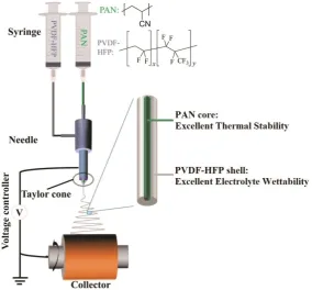
Herein, following this line, we successfully design a core-shell fiber network by coaxial
58
electrospinning to achieve both excellent thermal stability and electrochemical properties in the
59
same time: the thermally-stable and mechanically-strong PAN fibers as the core serve as rigid
60
framework to preserve the separator structure at elevated temperature; the PVDF-HFP as the shell
61
layer covering on the PAN core provides excellent electrolyte wettability. To prepare this core-shell
62
fiber network, coaxial electrospinning technique is employed (Figure 1). Typically, two syringes are
63
connected into a dual-nozzle, and precursor solutions of PAN and PVDF-HFP are injected into the
64
inner and outer channels of the dual-nozzle, respectively. Afterwards, the core-shell fiber network
65
can thus be produced through this technique and can be used as dual-functional separators for LIBs
66
with high performance and improved safety.
67
68
2. Materials and Methods
69
2.1 Materials
70
PAN (average Mw = 150,000, powder), PVDF-HFP (average Mw = 455,000; average Mn = 110,000,
71
pellets), dimethylformamide (DMF, 99.8%) and N-methyl-2-pyrrolidone (NMP, 99.5%) were
72
purchased from Sigma-Aldrich. All of these reagents were used without further purification.
73
Electrolyte (1 M LiPF6 dissolved in a mixture of ethylene carbonate (EC) and diethyl carbonate (DEC)
74
(v/v = 1:1), moisture < 10 ppm), commercial separator (Celgard 2400), poly(vinylidene fluoride)
75
(PVDF, HSV900, 99.5%), carbon black C45, LiNi1/3Co1/3Mn1/3O2 (NCM), lithium metal foil (99.9%),
76
copper foil (12 μm, 99.8%), aluminum (Al) foil (16 ± 2 μm, 99.54%) and coin cell type-CR2032 were
77
purchased from MTI Kejing Technology.
78
79
2.2 Method
80
The core-shell fiber network which was used as battery separators was fabricated by
81
dual-nozzle coaxial electrospinning. The core and shell precursor solutions were prepared by 8 wt%
82
PAN and 12 wt% PVDF-HFP dissolved in dimethylformamide (DMF), respectively. In more details,
83
the PAN precursor solution was prepared by dissolving 8 g PAN powder in 92 g DMF solution
84
under stirring for 3 hr at 70 °C. The PVDF-HFP precursor solution was prepared by dissolving 12 g
85
PVDF-HFP in 88 g DMF solution under stirring for 3 hr at room temperature. When both solutions
86
became homogeneous, the solutions were treated in ultrasonic bath for 30 min to remove bubbles.
87
The concentrations of our precursor solutions were set at a relatively low level because dilute
88
solutions help a partially mixing of PAN and PVDF-HFP which leads to strong interaction during
89
the electrospinning process. During electrospinning, 0.54 mL h-1 of PAN precursor solution was
90
extruded through the inner channel of the dual-nozzle while 1.08 mL h-1 of PVDF-HFP precursor
91
solution was extruded through the outer channel. Before voltage setup, it was important to extrude
92
PVDF-HFP solution firstly than extruding PAN solution. The electrospinning voltage was set to 16
93
kV in the beginning and then gradually lowered to 14.8 kV to form a stable Taylor cone. This
operation could avoid the deposition of solution droplets on the metallic collector. The obtained
95
electrospun fiber network was dried at 60 °C and the thickness of this fiber network was controlled
96
to be around 40 μm.
97
98
2.3 Characterization
99
The thermal gravimetric analysis (TGA, Netzsch, STA 409 PC) was performed in air at the
100
heating rate of 10 °C min-1. The morphology and elemental composition of the fiber network were
101
examined by transmission electron microscopy (TEM, Hitachi, HT7700), scanning electron
102
microscopy (SEM, Hitachi, SU-8010) and energy dispersive spectrometer (EDS, Hitachi, SU-8010).
103
To confirm the thermal behavior of the as-prepared separator, PAN@PVDF-HFP core-shell fiber
104
network and PVDF-HFP fiber network were heated in a temperature range from 25 to 250 °C. The
105
electrolyte uptake was measured by soaking the fiber network in 1 M LiPF6 in EC/DEC electrolyte
106
for 10 min, removing the residual electrolyte on the separator surface with air-laid paper and
107
weighing the soaked separator three times to obtain an accurate measurement. The mass gain
108
(average value) was therefore considered as the amount of electrolyte uptake. The contact angles of
109
electrolyte droplets on different separators were studied using contact angle meter (Dataphysics,
110
OCA15Pro).
111
112
2.4 Electrochemical Characterization
113
The LiNi1/3Co1/3Mn1/3O2 (NCM) half-cell was constructed using Li foil as the anode and NCM as
114
the cathode to examine the influence of separators on battery performances. The results were
115
compared between commercial separator and electrospun fiber networks. The NCM cathode was
116
fabricated by mixing NCM powder, carbon black C45 and PVDF (8 wt% PVDF in NMP) with the
117
weight ratio of 8:1:1. The resulting slurry was coated onto Al foil via a doctor-blade and the loading
118
of active materials was controlled at about 3 mg cm-2. The electrode was then dried in a vacuum oven
119
in air at 120 °C for 24 hours. The CR2032 coin cell was assembled by sandwiching the as-prepared
120
electrospun fiber network adding 80 μL electrolyte (1 M LiPF6 in mixture of EC/DEC with ratio of 1:1
121
by volume) between a piece of NCM cathode disc and a piece of lithium foil disc. Galvanostatic
122
discharge-charge cycling was performed with land system (CT2001A) in a potential range from 2.5 V
123
to 4.2 V at 0.1 C in the first 3 cycles for activation and at 1 C in the following cycles.
124
125
3. Results and Discussion
126
The morphology of the as-prepared electrospun core-shell nanofiber (denoted as
127
PAN@PVDF-HFP) is shown in Figure S1-S2. The diameter of each single fiber ranges from 300 nm to
128
500 nm without showing obvious agglomeration (Figure S1). From the TEM image, the core-shell
129
structure is observed and confirmed (Figure S2). The as-prepared electrospun fiber network
130
PAN@PVDF-HFP shows excellent flexibility, as no obvious cracks or defects can be observed after
131
rolled up or scrunched several times (Figure S3), indicating that the outer PVDF-HFP layer provides
132
sufficient mechanical support and protection to lead to an improved mechanical property.
134
Figure 1. Schematic illustration of the fabrication process of PAN@PVDF-HFP fiber using dual-nozzle coaxial
135
electrospinning technique. The PAN and PVDF-HFP precursor solutions are injected by syringes into the core
136
and shell channels of the needle, respectively. The PAN core with excellent thermal stability serves as
137
framework to preserve the entire structure at elevated temperature.
138
139
140
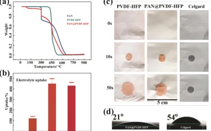
The content of PAN in the PAN@PVDF-HFP separator is determined by TGA (Figure 2a). Pure
141
PAN powder exhibits a three-step decomposition: the first characteristic weight loss peak is sharp
142
and clear with about 30% loss occurring at around 300 °C; the second weight loss behavior occurs in
143
the temperature range of 300 °C to 470 °C followed by the third weight loss which is around 500-600
144
°C. The weight loss of PVDF-HFP can be divided into two steps at around 450 °C and in the region of
145
450 °C to 520 °C. For PAN@PVDF-HFP core-shell nanofiber, the first weight loss at 300 °C is very
146
similar to the first characteristic sharp weight loss peak of PAN counting for about 30% loss and the
147
rest region on the curve behaves like a mixture of PAN and PVDF-HFP. Therefore this sharp peak at
148
300 °C is used to calculate the content of PAN in the polymer mixture. Specifically, this peak at 300
149
°C related to 30 wt% weight loss for pure PAN corresponds to an estimation of about 15%-17% total
150
loss in the PAN@PVDF-HFP composite. As a result, the calculated weight percentage of PAN in
151
PAN@PVDF-HFP is about 60%.
152
Electrolyte wettability of the battery separator plays a key role in the overall battery
153
performance. The current commercial battery separator based on PE or PP shows limited electrolyte
154
wettability which affects negatively on the battery performance. Moreover, many surface
155
modifications/coatings made to the commercial separator might also reduce the electrolyte uptake
156
and wettability. Therefore there is a strong demand to tackle this wettability issue. In order to
157
examine the electrolyte wettability of our electrospun fiber network, several tests including the
158
electrolyte uptake measurement, wetting velocity measurement, and contact angle test were
159
conducted on PAN@PVDF-HFP fiber network in comparison to commercial Celgard2400 separator
160
and electrospun PVDF-HFP fiber network (Figure 2b-2d). According to the calculated electrolyte
161
uptake results (Figure 2b), Celgard2400 separator can only absorb about 120 wt% of electrolyte
162
compared to its own weight. In contrast, both the PAN@PVDF-HFP fiber network and electrospun
163
PVDF-HFP fiber network show superior electrolyte wettability of up to 420 wt% electrolyte uptake.
164
In addition to the amount of electrolyte absorbed, the wetting speed is another important factor to
165
examine. Different separators are subjected to the measurements of spreading area of electrolyte
166
with respect to the period of time and the results are compared. As shown in Figure 2c, after
dropping a fixed amount of electrolyte droplet onto the commercial Celgard2400 separator, the
168
electrolyte droplet shows slow spreading even after 50 seconds. For PVDF-HFP and
169
PAN@PVDF-HFP fiber networks, the electrolyte spreads fast with similar speed. The wetting area
170
(round shape) on the separator by the liquid electrolyte droplet increases from 1.00 cm in diameter
171
right after the electrolyte droplet in contact with separator to 1.26 cm in diameter after 10 seconds
172
and 2.14 cm after 50 seconds, respectively. This implies that the PVDF-HFP accounts for the superior
173
wettability to liquid electrolyte and this improvement in electrolyte wettability is huge compared to
174
that for commercial separators. Since lithium ion conduction/transportation during battery
175
operations is always retarded or blocked by the poor wetting property and insufficient electrolyte
176
uptake of separators, it is thus expected that when used as separators, the PVDF-HFP fiber network
177
or the core-shell fiber with PVDF-HFP as the outer layer in contact with electrolyte could have little
178
negative effects on battery performance compared with commercial separators. In addition, the
179
electrolyte contact angle measurements further supports the above conclusion that PVDF-HFP outer
180
layer has superior electrolyte wettability. As shown from Figure 2d, the contact angle of electrolyte
181
droplet on commercial Celgard2400 separator is 54 ° while the contact angle of electrolyte droplet on
182
PAN@PVDF-HFP fiber network is 21 °. Both the contact angles were measured and recorded right
183
after electrolyte droplet in contact with the fiber network.
184
185
186
Figure 2. (a) TGA curves of PAN, PVDF-HFP and PAN@PVDF-HFP in air flow; (b) The amount of electrolyte
187
uptake for commercial Celgard2400 separator, PVDF-HFP fiber network and PAN@PVDF-HFP fiber network
188
(percentage on the basis of their own weight); (c) The spreading of electrolyte droplet on commercial
189
Celgard2400 separator, PVDF-HFP and PAN@PVDF-HFP fiber network with respect to time; (d) Contact angles
190
of commercial Celgard2400 separator and PAN@PVDF-HFP fiber network in the first second after electrolyte
191
dropping.
192
193
194
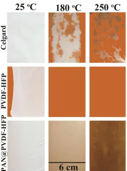
Thermal stability is another significant factor for battery separators to investigate. It is well
195
accepted that separator shrinkage under elevated temperature is one of the major origins to the
196
battery thermal runaway [27]. To examine the thermal stability of separators under similar
197
conditions to real battery operations, commercial Celgard2400, PVDF-HFP and PAN@PVDF-HFP
198
fiber network were clamped with two pieces of glass plates first, and were then heated from room
199
temperature to elevated temperature up to 250 °C for 10 min. A piece of brown-colored copper foil
was placed at the bottom of glass plates to make the observation clearer and more obvious (Figure
201
S4). As presented in Figure 3, commercial Celgard2400 separator suffers from several shrinkage at
202
180 °C and non-uniform distribution of pin-holes formation, which could lead to drastically
203
increased short-circuit hotspots and trigger the thermal runaway. At 250 °C the Celgard2400
204
separator shrinks dramatically and almost disappears. The residual materials turn into dark brown
205
to black color. The PVDF-HFP fiber network also could not endure the high temperature and melts
206
into a transparent viscous layer sticking onto the glass plates (Figure 3) above 180 °C. More typical
207
images demonstrating the melting behavior of PVDF-HFP can be found in Figure S5. In contrast, the
208
PAN@PVDF-HFP fiber network exhibits little shrinking nor does the fiber network melt at elevated
209
temperature up to 250 °C. As a result, the PAN core of the PAN@PVDF-HFP fiber network provides
210
sufficient heat resistance to enable the overall core-shell fiber with excellent thermal stability.
211
212
213
Figure 3. The thermal stability tests of commercial Celgard2400 separator, PVDF-HFP and PAN@PVDF-HFP
214
fiber network.
215
216
217
Furthermore, in order to obtain more details about the above temperature-dependent change of
218
separators during heating process, the morphology of these separators were carefully studied using
219
microscopes. Both PVDF-HFP and PAN@PVDF-HFP fiber networks were heated to 180 °C, 200 °C
220
and 250 °C and held at the elevated temperature for 10 min, and then characterized by SEM/EDS.
221
Figure 4 displays the morphology of the two types of separators under different temperatures for 10
222
min, starting from room temperature. For PAN@PVDF-HFP fiber network, though the PVDF-HFP
223
outer layer gradually melts and shrinks with the increasing temperature, the PAN core serving as
224
skeleton still supports and maintains the entire structure (Figure S6). In comparison, the PVDF-HFP
225
fiber network melts into a viscous fluid which is in accordance with the observations from Figure 3.
226
In addition, the elemental mapping results shown in Figure S7 before and after thermal treatment
indicate a uniform distribution of elements carbon (C), nitrogen (N), and fluorine (F) over the entire
228
PAN@PVDF-HFP fiber network.
229
230
231
Figure 4. The top-view SEM images of the pristine PAN@PVDF-HFP fiber network at (a) room temperature and
232
after thermal treated at (b) 180 oC, (c) 200 oC and (d) 250 oC, respectively; The inset in (a) is the TEM image of a
233
single PAN@PVDF-HFP fiber; The morphology of PVDF-HFP fiber network at (e) room temperature, (f) 180 oC,
234
(g) 200 oC and (h) 250 oC, respectively.
235
236
237
238
Figure 5. The electrochemical performances of NCM cells using Celgard2400 and PAN@PVDF-HFP separators.
239
The voltage range of the cycling is 2.5-4.2 V; (a) The charge-discharge voltage profiles at different C-rates for
240
cells using PAN@PVDF-HFP separators; (b) The rate capability at different C-rates for NCM cells using
Celgard2400 and PAN@PVDF-HFP separators; (c) The long-term cycling performances of NCM cells using
242
Celgard2400 and PAN@PVDF-HFP separators.
243
244
245
Finally, lithium-ion batteries using NCM cathodes, Li foil anodes, and the PAN@PVDF-HFP
246
fiber network as separators were constructed and subjected to electrochemical cycling. The voltage
247
profiles at various current rates ranging from 0.5 C to 2 C were demonstrated in Figure 5a, where the
248
cell using NCM cathode and PAN@PVDF-HFP as separator could deliver a high discharge capacity
249
of over 120 mAh g-1 even at 2 C rate. Moreover, the rate capability as well as long-term cycling tests
250
were also performed on batteries with NCM cathode and PAN@PVDF-HFP separator. And the
251
results were compared with batteries using same cathode but with commercial Celgard2400
252
separator. Specifically, as presented in Figure 5b, batteries with PAN@PVDF-HFP separator and
253
PVDF-HFP separator show similar rate behavior under low current rates from 0.1 C to 1 C.
254
However, under the high current rates such as 1.5 C and 2 C, batteries with PVDF-HFP separator
255
exhibit rapid capacity decay and unstable cycling behavior. In contrast, batteries with
256
PAN@PVDF-HFP separator show a superior rate capability with little capacity decay, and the
257
average charge capacity maintains at 128 mAh g-1 under 1.5 C and 123 mAh g-1 under 2 C,
258
respectively. This improvement in rate capability of batteries with PAN@PVDF-HFP separator
259
compared with commercial separator can be ascribed to the enhanced electrolyte wettability and
260
electrolyte uptake, which triggers facile ion transportation. Furthermore, long-term cycling was
261
conducted on both batteries. And both cells present a good cycling behavior for reversible capacity
262
over 130 mAh g-1 for more than 200 cycles with almost 90% capacity retention (Figure 5c). Therefore,
263
the batteries with our dual-nozzle coaxial electrospun core-shell nanofiber as separator show even
264
enhanced electrochemical properties compared with their commercial counterparts.
265
266
4. Conclusions
267
In conclusion, the rational design of a core-shell nanofiber network is successfully achieved via
268
our dual-nozzle, coaxial electrospinning technique. This PAN@PVDF-HFP core-shell fiber network
269
with PAN as the core and PVDF-HFP as the outer layer exhibit excellent heat resistance from PAN
270
core and excellent electrolyte wettability from PVDF-HFP shell in the same time. As a result, when
271
used as battery separators, this core-shell fiber network provides superior thermal stability with
272
little compromise or even some enhancement in battery performances. Therefore this core-shell
273
nanofiber as well as this design concept holds promise in next-generation energy storage devices.
274
Supplementary Materials: The following are available online. Figure S1. The SEM image of PAN@PVDF-HFP
275
core-shell fiber network. Figure S2. The TEM image of two PAN@PVDF-HFP fibers. Figure S3. The flexibility
276
test of PAN@PVDF-HFP separator. Figure S4. The thermal stability test of commercial separator, PVDF-HFP
277
and PAN@PVDF-HFP fiber network. Figure S5. Thermal stability tests of PAN film and PVDF-HFP film at 180
278
°C. Figure S6. SEM image showing the structural intactness of PAN@PVDF-HFP fiber network at 250 °C.
279
Figure. S7 Elemental mapping of selected area of PAN@PVDF-HFP fiber network.
280
Author Contributions: conceptualization, Y.Z. and Z.L.; methodology, Y.Z.; investigation, Y.L.;
281
writing—original draft preparation, Y.Z.; writing—review and editing, Y.L., Z.L.; supervision, Z.L.; project
282
administration, Y.Z.
283
Funding: The work was supported by the National Natural Science Foundation of China (No. U1564205),
284
Ministry of Science and Technology of China (No. 2013CB934000, 2016YFE0102200).
285
Conflicts of Interest: The authors declare no conflict of interest.
286
287
288
References
290
[1] Miao, Y.; Hynan, P.; von Jouanne, A.; Yokochi, A. Current Li-Ion Battery Technologies in
291
Electric Vehicles and Opportunities for Advancements. Energies 2019, 12, 1074.
292
[2] J. B. Goodenough, Y. Kim, Challenges for rechargeable Li batteries, Chem. Mater. 2010, 22, 587.
293
[3] J. M. Tarascon, M. Armand, Issues and challenges facing rechargeable lithium batteries, Nature
294
2001, 414, 359.
295
[4] Chen, J. Recent Progress in Advanced Materials for Lithium Ion Batteries. Materials 2013, 6,
296
156-183.
297
[5] Z. Liang, D. C. Lin, J. Zhao, Z. D. Lu, Y. Y. Liu, C. Liu, Y. Y. Lu, H. T. Wang, K. Yan, X. Y. Tao,
298
Y. Cui, Composite lithium metal anode by melt infusion of lithium into a 3D conducting
299
scaffold with lithiophilic coating, PNAS 2016, 113, 2862.
300
[6] Y. Zhao, Y. H. Jin, L. Wang, G. Y. Tian, X. M. He, The application of self-assembled hierarchical
301
structures in lithium-ion batteries, Progress in Chemistry, 2018, 30, 1761-1769.
302
[7] Z. Liang, K. Yan, G. Zhou, A. Pei, J. Zhao, Y. Sun, J. Xie, Y. Li, F. Shi, Y. Liu, D. Lin, K. Liu, H.
303
Wang, H. Wang, Y. Lu, Y. Cui, Composite lithium electrode with mesoscale skeleton via simple
304
mechanical deformation, Sci. Adv. 2019, 5, eaau5655.
305
[8] Y. Zhao, Y. Q. Kang, Y. H. Jin, L. Wang, G. Y. Tian, X. M. He, Recent Progress of Silicon-Based
306
and -Related Materials for Lithium-Ion Batteries, Progress in Chemistry, 2019, 31, DOI:
307
10.7536/PC180916.
308
[9] Z. Liang, X. Tao, Y. Cui, Black TiO2 Nanomaterials for Lithium–Sulfur Batteries, Black TiO2
309
Nanomaterials for Energy Applications, 2017, 275-304, DOI: 10.1142/9781786341662_0011.
310
[10] W. X. Ji, F. Wang, D. T. Liu, J. F. Qian, Y. L. Cao, Z. X. Chen, H. X. Yang, X. P. Ai, Building
311
thermally stable Li-ion batteries using a temperature-responsive cathode, J. Mater. Chem. A 2016,
312
4, 11239.
313
[11] K. Liu, Y. Y. Liu, D. C. Lin, A. Pei, Y. Cui, Materials for lithium-ion battery safety, Sci. Adv.
314
2018, 4, eaas9820.
315
[12] K. T. Lee, S. Jeong, J. Cho, Roles of surface chemistry on safety and electrochemistry in lithium
316
ion batteries, Acc. Chem. Res. 2013, 46, 1161.
317
[13] H. Li, D. B. Wu, J. Wu, L. Y. Dong, Y. J. Zhu, X. L. Hu, Flexible, high-wettability and
318
fire-resistant separators based on hydroxyapatite nanowires for advanced lithium-ion batteries,
319
Adv. Mater. 2017, 29, 1703548.
320
[14] X. N. Feng, M. G. Ouyang, X. Liu, L. G. Lu, Y. Xia, X. M. He, Thermal runaway mechanism of
321
lithium ion battery for electric vehicles: A review, Energy Storage Materials 2018, 10, 246.
322
[15] H. Lee, M. Yanilmaz, O. Toprakci, K. Fu, X. W. Zhang, A review of recent developments in
323
membrane separators for rechargeable lithium-ion batteries, Energy Environ. Sci. 2014, 7, 3857.
324
[16] H. Zhang, M. Y. Zhou, C. E. Lin, B. K. Zhu, Progress in polymeric separators for lithium ion
325
batteries, RSC Adv. 2015, 5, 89848.
326
[17] X. M. Zhu, X. Y. Jiang, X. P. Ai, H. X. Yang, Y. L. Cao, A highly thermostable ceramic-grafted
327
microporous polyethylene separator for safer lithium-ion batteries, ACS Appl. Mater. Interfaces
328
2015, 7, 24119.
329
[18] X. Z. Yan, Y. R. Wang, T. Yu, H. Chen, Z. B. Zhao, S. Y. Guan, Polyimide binder by combining
330
with polyimide separator for enhancing the electrochemical performance of lithium ion
331
batteries, Electrochimica Acta 2016, 216, 1.
332
[19] L. Pan, H. B. Wang, C. L. M. Wu, C. B. Liao, L. Li, Tannic-acid-coated polypropylene
333
membrane as a separator for lithium-ion batteries, ACS Appl. Mater. Interfaces 2015, 7, 16003.
334
[20] D. Z. Wu, L. Deng, Y. Sun, K. S. Teh, C. Shi, Q. L. Tan, J. B. Zhao, D. H. Sun, L. W. Lin, A
335
high-safety PVDF/Al2O3 composite separator for Li-ion batteries via tip-induced
336
electrospinning and dip-coating, RSC Adv. 2017, 7, 24410.
337
[21] N. Q. Liang, J. H. Fang, X. X. Guo, A simple approach for preparation of porous
338
polybenzimidazole membranes as a promising separator for lithium ion batteries, J. Mater.
339
Chem. A 2017, 5, 15087.
340
[22] P. Pankaj Arora, Z. M. Zhang, Battery separators, Chem. Rev. 2004, 104, 4419.
[23] J. K. Pi, G. P. Wu, H. C. Yang, C. G. Arges, Z. K. Xu, Separators with biomineralized zirconia
342
coatings for enhanced thermo- and electro-performance of lithium-ion batteries, ACS Appl.
343
Mater. Interfaces 2017, 9, 21971.
344
[24] X. M. Zhu, X. Y. Jiang, X. P. Ai, H. X. Yang, Y. L. Cao, A highly thermostable ceramic-grafted
345
microporous polyethylene separator for safer lithium-ion batteries, ACS Appl. Mater. Interfaces
346
2015, 7, 24119.
347
[25] Sun, G.; Sun, L.; Xie, H.; Liu, J. Electrospinning of Nanofibers for Energy Applications.
348
Nanomaterials 2016, 6, 129.
349
[26] J. J. Zhang, Z. H. Liu, Q. S. Kong, C. J. Zhang, S. P. Pang, L. P. Yue, X. J. Wang, J. H. Yao, G. L.
350
Cui, Renewable and superior thermal-resistant cellulose-based composite nonwoven as
351
lithium-ion battery separator, ACS Appl. Mater. Interfaces 2013, 5, 128.
352
[27] J. H. Dai, C. Shi, C. Li, X. Shen, L. Q. Peng, D. Z. Wu, D. H. Sun, P. Zhang, J. B. Zhao, A rational
353
design of separator with substantially enhanced thermal features for lithium-ion batteries by
354
the polydopamine-ceramic composite modification of polyolefin membranes, Energy Environ.
355
Sci. 2016, 9, 3252.
356
[28] S. Gong, H. Jeon, H. Lee, M. H. Ryou, Y. M. Lee, Effects of an integrated separator/electrode
357
assembly on enhanced thermal stability and rate capability of lithium-ion batteries, ACS Appl.
358
Mater. Interfaces 2017, 9, 17814.
359
[29] F. Croce, M. L. Focarete, J. Hassoun, I. Meschini, B. Scrosati, A safe, high-rate and high-energy
360
polymer lithium-ion battery based on gelled membranes prepared by electrospinning, Energy
361
Environ. Sci. 2011, 4, 921.
362
[30] X. M. Zhu, X. Y. Jiang, X. P. Ai, H. X. Yang, Y. L. Cao, TiO2 ceramic-grafted polyethylene
363
separators for enhanced thermostability and electrochemical performance of lithium-ion
364
batteries, J. Membr. Sci. 2016, 504, 97.
365
[31] S. M. Kang, M. H. Ryou, J. C. Choi, H. Lee, Mussel- and diatom-inspired silica coating on
366
separators yields improved power and safety in Li-ion batteries, Chem. Mater. 2012, 24, 3481.
367
[32] M. H. Liu, P. P. Zhang, L. T. Gou, Z. Y. Hou, B. Huang, Enhancement on the thermostability
368
and wettability of lithium-ion batteries separator via surface chemical modification, Materials
369
Letters 2017, 208, 98.
370
[33] T. H. Cho, M. Tanaka, H. Onishi, Y. Kondo, T. Nakamura, H. Yamazaki, S. Tanase, T. Sakai,
371
Battery performances and thermal stability of polyacrylonitrile nano-fiber-based nonwoven
372
separators for Li-ion battery, J. Power Sources 2008, 181, 155.
373
[34] L. Cao, P. An, Z. Xu, J. Huang, Performance evaluation of electrospun polyimide non-woven
374
separators for high power lithium-ion batteries, J. Electroanal. Chem. 2016, 767, 34.
375
[35] D. Bansal, B. Meyer, M. Salomon, Gelled membranes for Li and Li-ion batteries prepared by
376
electrospinning, J. Power Sources 2008, 178, 848.
377
[36] Z. Li, W. Q. Wang, Y. Han, L. Zhang, S. S. Li, B. Tang, S. M. Xu, Z. H. Xu, Ether modified
378
poly(ether ether ketone) nonwoven membrane with excellent wettability and stability as a
379
lithium ion battery separator, J. Power Sources 2018, 378, 176.
380
[37] C. M. Costa, M. Maria, M. M. Silva, S. Lanceros-Méndez, Battery separators based on
381
vinylidene fluoride (VDF) polymers and copolymers for lithium ion battery applications, RSC
382
Adv. 2013, 3, 11404.
383
[38] K. Xiao, Y. Y. Zhai, J. Y. Yu, B. Ding, Nanonet-structured poly(m-phenylene
384
isophthalamide)-polyurethane membranes with enhanced thermostability and wettability for
385
high power lithium ion batteries, RSC Adv. 2015, 5, 55478.