Dynamic Stability Improvement of Grid
Connected PMSG Based Offshore Wind Farm
Using a STATCOM
P.Niranjan1, M.Rama Sekhara Reddy 2PG Student [EPS], Dept. of EEE, JNTU Engineering College, Anantapur, India1 Assistant Professor, Dept. of EEE, JNTU Engineering College, Anantapur, India2
ABSTRACT:This paper presents the dynamic stability improvement of the offshore wind farm(OWF) connected to
power grid using a static synchronous compensator(STATCOM) .The offshore wind farm is simulated by taking the four parallel operated permanent magnet generators(PMSG) of 5MW and the onshore power system is simulated by synchronous generator fed to an infinite bus through two parallel transmission lines. The STATCOM controller is implemented using two types of controllers: conventional PID controller and Fuzzy logic controller(FLC). The PID controller is designed using pole placement approach and the fuzzy logic controller is implemented using sugeno type fuzzy interface system. At the end the response with respect to both are compared.
KEYWORDS: Dynamic stability, PMSG, Static synchronous compensator, PID controller, Fuzzy logic
controller(FLC).
I.INTRODUCTION
In present days due to increase in the demand of electrical generation, the larger renewable electrical energy generation is best choice than conventional generation from the fossil fuels. Since oceans cover more than 70% surface of earth, the OWF can be extensively developed at the specific locations of the world in the future. In present OWF is more used by European countries.
One of the simple methods of running OWF is to connect the output terminals of several permanent magnet synchronous generators(PMSGs) together and then connected to power grid through full rated power converters, step up transformers and undersea cables. Currently, wind doubly-fed induction generators(DFIGs) and wind permanent-magnet synchronous generators have been widely used in high offshore wind farms(OWFs). Due to large interconnections and fast acting controllers there is low frequency oscillations are exist in the rotor of generators in addition to disturbances like grid fault or control device failures in high capacity generation system. The stability related to these oscillations is termed as dynamic stability. The dynamic stability is the extension of study state stability by taking the effect of controllers. To compensate the fluctuating components the STATCOM is presented in this paper.
This paper is organized as below. The configuration and the employed model for studied OWF with STATCOM. The design procedure for the PID controller of proposed STATCOM and fuzzy logic controller were depicted. This paper focus on the dynamic stability of the studied system with the above two controllers and are compared with without controller under three phase short circuit fault is described. Finally, specific conclusions of this paper are described.
II.
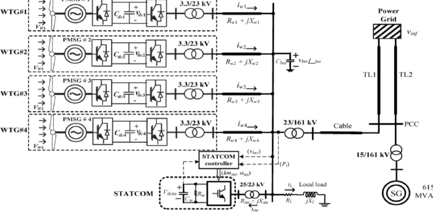
CONFIGURATION OF THE STUDIED SYSTEMFig.1 shows the configuration of studied system. The wind farm is modeled with four parallel operated PMSG based wind turbine generators of 5MW each. To maintain the grid interconnection standards the PMSGs are joined at common offshore ac bus through full rated power converter and 3.3/23 kV transformers. The wind farm is interconnected to onshore power system through step up transformer of 23/161 kV and the cable at the point of common coupling(PCC) of onshore power system. The onshore power system is modeled as one-machine infinite-bus(OMIB) system. The OMIB system is modeled with the synchronous generator(SG) of 615MVA is connected to the grid through step up transformer of 15/161 kV and two parallel transmission lines(TL1 and TL2). The STATCOM of ±5MVAR is connected at the common offshore ac bus.
Fig. 1 Configuration of studied offshore wind farm with STATCOM The employed mathematical models of studied system are described below.
1) Wind turbine
The captured mechanical power (in W) by wind turbine is
Pm= ρ.Ar.Vw3.Cp (λ, β) (1)
Where air density (kg/m2), Ar is the blade swept area(m2), Vw is the wind speed in (m/s) and Cp is the dimensionless
power coefficient of wind turbine. The cut in, rated and cutout wind speeds of studied wind turbine are 4, 14 and 25 m/s respectively.
2) Mass spring damper system
Fig. 2 Two inertia reduced order model of each WT connected rotor shoft of wind PMSG
The per unit equations of motion for the two inertia reduced order model of coupling of WT to the PMSG is expressed by
2Hh p(ωh)=Tm-Khgθhg-Dhgωh (2)
2Hg p(ωg)=Khgθhg+Dhgωh-Te (3)
p(θhg)= ωh(ωh-ωg) (4)
Where p is the differential operator with respect time; Hh andHg are the inertias of the hub and the PMSG respectively; ωhand ωg are the angular speeds of the hub and the PMSG, respectively; Dhg, Khg and θhg are the mechanical damping
coefficient, spring constant, and rotor-angle difference between the hub and the PMSG, respectively; Tm and Te are the
mechanical input torque and the electromagnetic torque of the PMSG, respectively.
3) PMSG and power converters
The p.u. d-q axis equivalent circuit model of studied PMSG, where q-axis is fixed on the machine rotor and rotate at rotor speed, can be expressed by
(5)
(6) In the above Ψq and Ψd are given by
Ψq=-(Xmq+Xls)iqs=-Xqiqs (7)
Ψd=-(Xmd+Xls)ids+Xmdi’m=-Xdids+Xmdi’m (8) where Ψ is the per-unit flux linkage, vs is the per–unit stator winding voltage, is is the per-unit stator winding current,
Xm is the per-unit magnetization reactance, Xl is the per-unit leakage reactance, i’m is the per-unit magnetization current, ωr is the per-unit rotational speed, and ωb is the per-unit base speed.
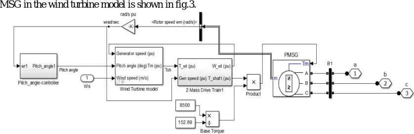
The PMSG in the wind turbine model is shown in fig.3.
The power converters used to control the gird parameters is shown in Fig. 4.
Fig. 4 power converters of the studied wind PMSG
The input – axis per-unit voltages of the voltage-source converter (VSC) converter of a wind PMSG can be expressed by
vcond=kmcondvdc (9)
vconq=kmconqvdc (10)
The output – axis per unit voltages of the VSC inverter of a wind PMSG can be written by
vinvd=kminvsin(αinv)vdc (11)
vinvq=kminvcos(αinv)vdc (12)
In Matlab/Simulink model this power converter is implemented using the universal bridge with IGBTs as the power electronic devices.
4) STATCOM controller
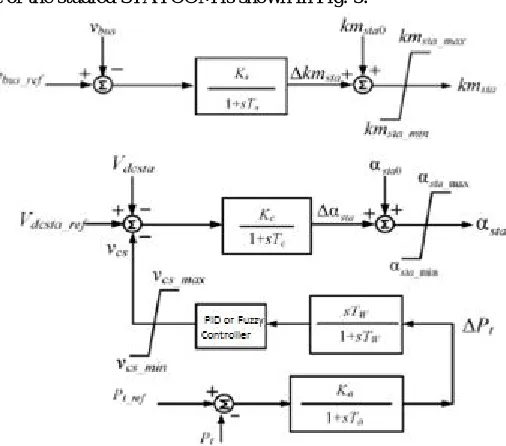
The proposed control circuit of the studied STATCOM is shown in Fig. 5.
Fig. 5 the control diagram for employed STATCOM The per unit d and q axis output voltages of the proposed STATCOM are
vqstat =Vdcstakmstacos(θbus+αsta) (13)
(Cm)p(vdcsta) =ωb[Idcsta(Vdcsta/Rm)] (15)
Where
Idc =iqstakmstacos(θbus+αsta)+idsta kmstasin(θbus+αsta) (16)
The STATCOM controllers of PID and FLC are used in this system are explained in the sections III & IV.
III.PID CONTROLLER
PID controller is one of the most common controlling devices in the market. Because of its very simple control structure and the linear control methodology, PID control is important in many industries and has been widely used in electrical, mechanical, hydraulic, fluidic, and pneumatic systems. A PID controller continuously calculates an error value as the difference between a measured process variable and a desired set point.
The STATCOM controller with PID controller is shown in fig.6.
Fig. 6 The control circuit of STATCOM using the PID controller
IV.FUZZY CONTROLLER
Since power system dynamic characteristics are complex and variable, conventional control methods cannot provide desired results. Intelligent controller can be replaced with conventional controller to get fast and good dynamic response in load frequency problems. Fuzzy Logic Controller (FLC) can be more useful in solving large scale of controlling problems with respect to conventional controller are slower. Fuzzy logic controller is designed to minimize fluctuation on system outputs. There are many studied on power system with fuzzy logic controller. A fuzzy logic controller consist of three sections namely fuzzifier, rule base and defuzzifier as shown in fig.7.
Fig. 7 Fuzzy interference system
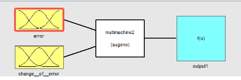
negative big(NB). The variables used for output are increase big(IB), increase medium(IM), increase small(IS), constant value(KV),decrease small(DS), decrease medium(DM), decrease big(DB). The rules will be formed according to application. Rules which had developed in FIS should be saved in a file by exporting it to file, for each and every operation with fuzzy model the FIS file with rules should import from file and should be exported to workspace then only the model will run and output will shown. The membership functions of inputs of this system are shown in fig.8.
Fig. 8 the membership functions of FLC
Table 1: Fuzzy logic rule box
From the above rule box we can form the rule base with two inputs and one output, the rules as follows Rule 1 : if (error is NB) and (change of error is PB) then (output is KV)
Rule 2 : if (error is NM) and (change of error is PB) then (output is IS) Rule 3 : if (error is NS) and (change of error is PB) then (output is IM)
.
Rule 49: if (error is PB) and (change of error is NB) then (output is KV)
V. RESULT AND DISCUSSION
Fig. 9 Matlab/Simulink model of the studied system
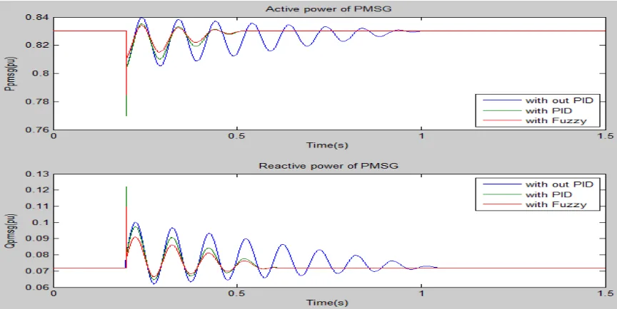
The system is tested for dynamic response of the system by applying the fault at t=0.2s and cleared at t=0.21s.The active and reactive powers of the PMSG, STATCOM and the synchronous generator with the above disturbance are shown in the Fig. 10 to Fig.12. The rotor angle and angular velocity of the SG are shown in the Fig.12. The voltage waveforms at point of common coupling (PCC) and the STATCOM buses are shown in Fig.13.
Fig. 11 P and Q supplied by STATCOM
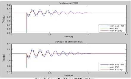
Fig. 13 Voltages at the PCC and STATCOM buses
By observing the all the above results, the system is disturbed by applying the fault at t=0.2s and cleared at t=0.21s. The reactive power demanded by the system during the fault is supplied by STATCOM. The outputs with fuzzy logic controller have the low magnitude of oscillations compared to the PID controller. Not only the reactive power but also the system voltage became steady at t=0.6s using the FLC and the synchronous generator rotor angle oscillations are reduced with the proposed STATCOM controllers.
VI.CONCLUSION
This paper has presented the dynamic stability improvement of an offshore wind farm using a STATCOM. The STATCOM controller is implemented with PID controller and Fuzzy logic controller. The three phase short circuit fault at the wind farm has been performed to demonstrate the effectiveness of proposed controllers. By observing the results with both the controllers, the Fuzzy logic controller has better performance with small oscillations compared to PID controller for the proposed system. So FLC is best choice than conventional PID controller for the studied system.
REFERENCES
[1] Li Wang,and Dinh-Nhon Truong, ”Dynamic stability improvement of four parallel- operated PMSG-based offshore wind turbine generators fed to a power system using a STATCOM’, IEEE Trans. Power delivery, vol. 28, no. 1, pp. 111–119, Jan 2013.
[2] A. E. Leon, J. M. Mauricio, A. Gomez-Exposito, and J. A. Solsona, “An improved control strategy for hybrid wind farms,” IEEE Trans. Sustain. Energy, vol. 1, no. 3, pp. 131–141, Oct. 2010.
[3] A. Uehara, A. Pratap, T. Goya, T. Senjyu, A. Yona, N. Urasaki, and T. Funabashi, “A coordinated control method to smooth wind power fluctuations of a PMSG-based WECS,” IEEE Trans. Energy Convers., vol. 26, no. 2, pp. 550–558, Jun. 2011.
[4] H. Gaztanaga, I. Etxeberria-Otadui, D. Ocnasu, and S. Bacha, “Real time analysis of the transient response improvement of fixed-speed wind farms by using a reduced-scale STATCOM prototype,” IEEE Trans. Power Syst., vol. 22, no. 2, pp. 658–666, May 2007.
[5] A. Jain, K. Joshi, A. Behal, and N. Mohan, “Voltage regulation with STATCOMs: Modeling, control and results,” IEEE Trans. Power Del., vol. 21, no. 2, pp. 726–735, May 2006.
[6] A. H. Norouzi and A. M. SharafI, “Two control schemes to enhance the dynamic performance of the STATCOM and SSSC,” IEEE Trans. Power Del., vol. 20, no. 1, pp. 435–442, Jan. 2005.
[7] K. V. Patil, J. Senthil, J. Jiang, and R. M. Mathur, “Application of STATCOM for damping torsinal oscillations in series compensated AC system,” IEEE Trans. Energy Convers., vol. 13, no. 3, pp. 237–243, Sep. 1998.