ISSN (Print) : 2347 - 6710
I
nternationalJ
ournal ofI
nnovativeR
esearch inS
cience,E
ngineering andT
echnology Volume 3, Special Issue 3, March 20142014 International Conference on Innovations in Engineering and Technology (ICIET’14) On 21st&22ndMarch Organized by
K.L.N. College of Engineering, Madurai, Tamil Nadu, India
ABSTRACT— This paper presents the analysis of load frequency control (LFC) of a deregulated two-area power system with Doubly Fed Induction Generators (DFIGs) integrated into both the areas. The deregulation of power system has led to develop the new companies for generation, transmission and distribution of power. To study the effects of the bilateral contracts of companies on the system dynamics, the conventional two-area power system is modified. The LFC becomes even more challenging when wind generators are also integrated into the system in deregulated environment and also creates highly competitive and distributed control environment. The overall inertia of the system reduces during disturbances, as the wind unit does not provide inertia and isolates from the grid. To provide inertial support to the system through modified inertial control scheme and arrests the frequency deviation after disturbance by DFIGs integration. To improve the frequency response of the system the kinetic energy of the wind turbine is drawn as the inertial control responds to frequency variations. The optimal values of the speed control parameters of the DFIG-based wind turbine have been obtained using Particle Swarm Optimization (PSO) technique used to enhance the participation of the doubly fed induction generator (DFIG) in the frequency control.
KEYWORDS- Frequency regulation, Deregulated power system, doubly fed induction generator (DFIG)
I. INTRODUCTION
Load–frequency control (LFC) is important in electric power system design and operation. The objective of the LFC in an interconnected power system is to maintain the frequency of each area within limits and to keep tie-line power flows within some pre-specified tolerances by adjusting the MW outputs of the generators so as to accommodate fluctuating load demands. A well designed and operated power system must cope with changes in the load and with system disturbances, and it should
provide high level of power quality while maintaining both voltage and frequency within tolerance limits. Subjected to any disturbance, As a result the deviation occurs about the operating point such as nominal system frequency, scheduled power exchange to the other areas which is undesirable[1]. The LFC issues have been tackled with by the various researchers in different time through AGC regulator, excitation controller design and control performance with respect to parameter variation/uncertainties and different load characteristics.Several control strategy such as integral control, optimal control, variable control have been used to control the frequency and to maintain the scheduled regulation between the interconnected areas. One major advantage of integral controller is that it reduces the steady state error to zero, but do not perform well under varying operating conditions and exhibits poor dynamic performance. An optimization of feedback controller and Proportional-Integral-Derivative (PID) controller is focused in [2].Due to non-linearity in various segregated components and design of the controller. The further research in LFC has been carried out by use of various soft computing techniques. Artificial neural network controller (ANN) is implemented in paper [3] which offers many benefits in the area of nonlinear control problems, particularly when the system is operating over the nonlinear operating range.
The controller parameters plays a vital role for its performance, thus it should be tuned properly with suitable optimization techniques like genetic algorithm (GA), particle swarm optimization (PSO), simulated annealing (SA). In [4] several kinds of machines are used in wind energy conversion system (WECS), but variable- speed generators such as doubly fed induction machines (DFIM) and permanent magnet synchronous machines (PMSM) are prevailing among others. An important feature of DFIM and PMSM is the possibility for their active and reactive power outputs to be controlled as required by system operators. A fraction of the kinetic energy stored in rotational masses to be released in order to provide earlier frequency support is discussed in [5].The dynamic contribution of doubly fed induction generator (DFIG)-based wind turbine in system frequency regulation is presented in [6]. Thus, wind generators only provide primary frequency control while the final generation has to be taken over by the conventional plants.
Automatic Generation Control in Restructured
Power System with Wind Integrated System
Prathibha M
#1, Bhavani M
*2#1
PG Scholar, Department of Electrical & Electronics Engineering, Anna University, Regional Office, Madurai, India
Copyright to IJIRSET www.ijirset.com 462 M.R. Thansekhar and N. Balaji (Eds.): ICIET’14
Yajvender Pal verma [7] analyse the Load frequency control (LFC) of a deregulated two-area hydro-thermal power system using fuzzy logic controller, with doubly fed induction generators (DFIGs) integrated into both the control areas. Optimal values of the speed control parameters of the DFIG-based wind turbine have been obtained using integral square error (ISE) technique.
In this work, it is proposed to analyze the AGC system for two area hydro-thermal power system in deregulation and related issues concerning the integration of new renewable power generation. It is aimed to minimize the frequency deviation and tie line power deviation while integrating wind energy system. For further improvement, the speed control parameters of Double Fed Induction Generator (DFIG) based wind turbine have to be optimized by using Particle swarm optimization (PSO).The simulations will be done using MATLAB SIMULINK.
Figure 1 Block Diagram of Two- area system for deregulated market with DFIG integrated
II. DEREGULATED POWER SYSTEM
The electrical power system is quite complex and dynamic in nature. This sector was largely in hands of vertical integrated utilities (VIUs), which own generation, transmission and distribution system that supply power to consumers at regulated rates. After restructuring, new organizations viz., generation companies (GENCOs), transmission companies (TRANSCOs), distribution companies (DISCOs), and independent system operators (ISO) have emerged. The restructuring also encourages independent power producers (IPPs) by making generation license free. Under deregulation the first step was to separate the generation of power from transmission and distribution, thus putting the generation on the same footings as the IPPs.
Disco participation matrix (DPM) is used to express the contracts between various Gencos and Discos in matrix form. This helps in easy visualization of these contracts. Equation (1) represents the DPM for the two-area system, each having two Gencos and two Discos.
(1)
Any entry cpf12 in Eq. (1) corresponds to the fraction of the total load power contracted by Disco2 from Genco1. The number of rows in DPM matrix corresponds to Gencos and numbers of columns equal to the number of Discos. Coefficients that distribute ACE to several GENCOs are termed as “ACE participation factors”.
𝑐𝑝𝑓𝑖 ij=1.0 (2)
Under steady state conditions the power flows on the tie-line is given by
𝛥𝑃𝑡𝑖𝑒 12𝑠𝑐 = 𝑐𝑝𝑓12𝛥𝑃𝐿2− 𝑐𝑝𝑓21𝛥𝑃𝐿1 (3)
The actual power flow through tie-line is given as
𝛥𝑃𝑡𝑖𝑒 12𝑎𝑐𝑡 = 2𝜋𝑇12
𝑠 (𝛥𝑓1− 𝛥𝑓2) (4)
The tie-line power error at any instant can be calculated as
𝛥𝑃𝑡𝑖𝑒 12𝑒𝑟𝑟 = 𝛥𝑃
𝑡𝑖𝑒 12𝑎𝑐𝑡 − 𝛥𝑃𝑡𝑖𝑒 12𝑠𝑐 (5)
The error signal is used to generate area control error (ACE) as
𝐴𝐶𝐸1= 𝐵1𝛥𝑓1− 𝛥𝑃𝑡𝑖𝑒 12𝑒𝑟𝑟 (6)
𝐴𝐶𝐸2= 𝐵2𝛥𝑓2− 𝑎12𝛥𝑃𝑡𝑖𝑒 12𝑒𝑟𝑟 (7)
III. DFIG MODELLING
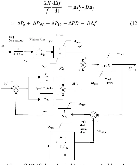
Traditionally, the wind units do not participate in load frequency control. But, now with advanced control, the kinetic energy stored in the mechanical system of the wind turbines can be extracted with variable speed generators. The DFIG based wind turbines can produce power with variable mechanical speed and extract kinetic energy to support the primary frequency regulation. Although, the steady-state active power delivered to the grid by a DFIG depends on the wind speed, the power can be dynamically controlled to a certain extent by utilizing the stored mechanical energy. In this paper, the dynamic model of DFIG-based wind turbine control DFIG-based on frequency changedepicted in Fig. 2 An additional control signal helps to adapt the power set-points ∆𝑃𝑓∗ as a function of deviation and rate of change of frequency. The controllers try to keep the turbine at its optimal speed in order to produce the maximum power. The controller provides a power set-point ∆𝑃ω∗ that is based on measured speed and measured electrical power. The support to primary frequency control depends on activation of this additional loop, as the grid frequency exceeds certain limits. As the system frequency drops, the set-point torque is increased, the rotor slows down, and kinetic energy is released. ∆PNC has two components: ∆𝑃𝑓∗, the additional reference point based on frequency change as given in with conventional inertial control, ∆𝑃𝑓∗, which is based on optimum turbine speed as a function of wind speed, discussed here:
∆𝑃𝑓∗ = - Kdf
𝑑𝑓
𝑑𝑡 - Kpf∆𝑓 (8)
point ∆𝑃ω∗•, forcing the speed to follow a desired speed reference, is given as
∆𝑃𝑤∗ = - Kwp (ω*- ω) + Kwi (ω ∗ − ω)t (9)
Where Kwp and Kwi are constants of the PI controller, providing fast speed recovery and transient speed variation, which helps non-conventional generators to supply the required active power to reduce deviations. The total non-conventional power injection is given by PNC as under:
PNC =∆𝑃𝑓∗ + ∆𝑃ω∗ (10)
The system inertia is controlled by Kdf, whereas Kpf provides the system damping, as given below
2𝐻 𝑓 + Kdf
d∆𝑓
dt = ∆𝑃𝑓− 𝐷∆𝑓
= ∆𝑃𝑔+ ∆𝑃𝑁𝐶− ∆𝑃12− ∆𝑃𝐷 − (𝐾𝑝𝑓+ 𝐷)∆𝑓 (11)
The contribution of the DFIG toward system inertia in modified inertial control is given as
2𝐻 𝑓
d∆𝑓
dt = ∆𝑃𝑓– 𝐷∆𝑓
= ∆𝑃𝑔+ ∆𝑃𝑁𝐶− ∆𝑃12− ∆𝑃𝐷 − 𝐷∆𝑓 (12)
Figure 2 DFIG-based wind turbine control based on frequency change
The reference point ∆𝑃𝑓∗is obtained from Eq. (13) and is given as
∆Pf∗=1
R(∆X2) (13)
Where R is the droop constant as used conventionally and ∆X2 is the frequency change measured where the wind turbine is connected to the network. The frequency term
(∆X2) used in Eq. (9) is the result of a washout filter, the active power injected by the wind turbine is PNC. The power injected is compared with PNCref so as to obtain the maximum power output, which is obtained by maintaining reference rotor speed, where maximum power is obtained. The mechanical power captured by the wind turbine is given by Eq. (14):
Where
𝜌is the air density in kg/m3, Ar is the rotor swept area in m2,
Cp:opt is the maximum value of the Cp(λ)curve at a pitch angle β=0
Snwind speed rating in MW and ω𝑠 is the wind speed
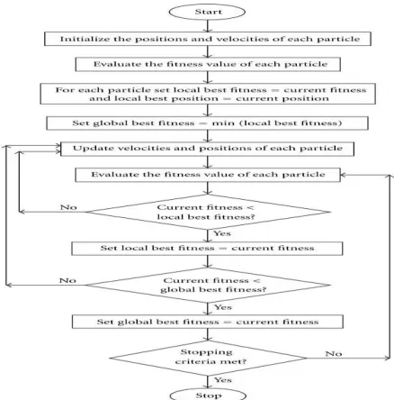
IV.PARTICLE SWARM OPTIMIZATION
In PSO algorithm, the system is initialized with a population of random solutions, which are called particles, and each solution is also assigned a randomized velocity. Each particle is treated as a valueless particle in g-dimensional search space and keeps track of its coordinates in the problem space associated with the best solution and this value is called pbest. The overall best value and its location obtained so far by any particle in the group that was tracked by the global version of the particle swarm optimizer gbest. The PSO concept consists of changing the velocity of each particle toward its pbest and gbest locations at each time step. As example, the jth particle is represented as xj = (xj,1 , xj,2 , . . . ,xj,g) in thegdimensional space. The best previous position of the jth particle is recorded and represented as pbestj = (pbestj,1 , pbestj,2 , . . , pbestj,g). The selection of best particle among all particles in the group is represented by the gbestg.
The rate of the position change (velocity) for particle j is represented as vj = (vj,1, vj,2, . . . , vj,g). The modified velocity and position of each particle can be calculated using the current velocity and distance from pbestj,g to gbestg as shown in the following formulas:
𝑉𝑗 .𝑔 𝑡+1 = 𝑊. 𝑉𝑗 .𝑔 𝑡 + 𝐶1∗ 𝑟𝑎𝑛𝑑 ∗ 𝑝𝑏𝑒𝑠𝑡𝑗 .𝑔− 𝑥𝑗 .𝑔 𝑡
+ 𝐶2∗
𝑟𝑎𝑛𝑑 ∗ 𝑔𝑏𝑒𝑠𝑡𝑗 .𝑔− 𝑥𝑗 .𝑔 𝑡
(15)
𝑥𝑗 .𝑔 𝑡+1 = 𝑥𝑗 .𝑔 𝑡+1 + 𝑉𝑗 .𝑔 𝑡+1 (16)
j = 1, 2, …,n g = 1, 2, …,m
where
nnumber of particles in a group;
mnumber of members in a particle;
tpointer of iterations(generations); 𝑉𝑗 .𝑔 𝑡 velocity of particle j at iteration t;
winertia weight factor;
c1, c2 acceleration constant;
rand( ) random number between 0 and 1; 𝑥𝑗 .𝑔 𝑡 current position of particle j at iteration t;
pbestjpbestof particle j;
gbestgbestof the group
Copyright to IJIRSET www.ijirset.com 464 M.R. Thansekhar and N. Balaji (Eds.): ICIET’14
Figure 3 Flow chart for Particle swarm optimization
A.Advantages of PSO
(1) PSO has no overlapping and mutation calculation. The search can be carried out by the speed of the particle. During the development of several generations, only the most optimist particle can transmit information onto the other particles, and the speed of the researching is very fast.
(2) The calculation in PSO is very simple. Compared with the other developing calculations, it occupies the bigger optimization.
(3) PSO adopts the real number code, and it is decided directly by the solution. The number of the dimension is equal to the constant of the solution
V. SIMULATION RESULTS AND DISCUSSION
The simulations have been conducted in a two-area hydro thermal system in an open access environment to investigate the role of the DFIG in system frequency control..The simulations have been conducted in Simulink in MATLAB 7.0. The interaction between the DFIG-based wind turbine and traditional plants has been investigated for a load perturbation of 2% in area-1 for wind penetration of 10 percent. In an open access market scenario, the Gencos and the Discos have bilateral contract agreements. In this case the DPM has been taken as follow:
0.5 0.25 0 0.3 0.2 0.25 0 0
0 0.25 1 0.7 0.3 0.25 0 0
(17)
A. Frequency Deviation in Two-Area System with and without DFIG
Frequency responses of the two-area deregulated power system are presented in Fig. 4 for with and without DFIG in area-1.
The results indicated that the frequency response has lower excursions when the DFIG is participating in the frequency control. However, without the DFIG, the overshoots (OS) and the undershoots (US) are higher and the settling time also is larger.
Figure 4 Frequency deviations in area-1
Frequency responses of the two-area deregulated power system with DFIG are presented in Fig. 5 area-2.The DFIG reacts fast and provides active power support proportional to frequency deviation. The inertial support is provided by the DFIGs by lowering their rotor speeds and transferring more kinetic energy into the grid and compensating the load perturbation. It can be seen that frequency deviation is smallest when DFIGs are providing frequency support.
Figure 5 Frequency deviations in area-2
B. Tie-linePower Deviation in Two Area System
Fig 6 shows the power deviation response of the Two-Area AGC System in Restructured Scenario
Figure 6 power deviation of the Two-Area AGC System in Restructured Scenario.
C. Undershoot and Overshoot Performance of Frequency Responses with and without DFIG
Undershoot and Overshoot values of obtained frequency response and compared in Table 1.obviously the values are reduced while adding with DFIG.
Table 1 Undershoot and Overshoot of Frequency Responses with and Without DFIG
D.Optimization Results
A better performance obtained with the implementation of PSO-based PID controller tuning. In the PSO-PSO-based PID controllers (PSOPID), different performance index gives different results. Furthermore, Fig.7 shows a sample of the trajectory of the PI parameters during optimization to see the convergence of the optimized solution. The PID parameters are obtained for 50 iterations.
Figure 7 Convergence Graph for fitness value After optimizing the parameter of DFIG using Particle swarm optimization the frequency deviation in area-1is shown in fig 8
Figure 8 Frequency deviations in area-1
Figure 9 and 10 shows the response of frequency deviation in area-2 and tie-line deviation
Figure 9 Frequency deviations in area -2
Figure 10 Tie-line Power deviations
Optimized Values of PI controller after tuned using Particle Swarm Optimization is shown in table 2.
Table 2 Optimized parameters of two –area system
Table 3 shows the comparison values of frequency and tie-line power deviation of two area system without DFIG and with DFIG tuned using Particle swarm optimization.
Table 3 Comparison of step response performance
Performance With DFIG Without DFIG
Hz
∆f1
Hz
Undershoot Overshoot
-0.0709 0.0307
-0.2067 0.1022
∆f2
Hz
Undershoot Overshoot
-0.0466 0.0384
-0.0681 0.0584
Area-1 Area-2
Kwi1 Kwp1 Kwi2 Kwp2
0.07726 0.41376 0.83077 0.6303
Settling Time in seconds
Parameters Without DFIG
WithDFIG tuned using PSO
∆f1 10.64 3.38
∆f2 21.26 10.86
Tie –line power deviations
Copyright to IJIRSET www.ijirset.com 466 M.R. Thansekhar and N. Balaji (Eds.): ICIET’14
VI .CONCLUSION
This paper investigates the role of DFIG-based wind turbine towards LFC in a two-area power system in an open access environment. The modified inertial control scheme is used for the DFIG which provides inertial support to the system during transients and arrests the fall in frequency. The parameters of the DFIG controller have been optimized using particle swarm optimization (PSO) to enhance its participation in the frequency regulation. The DFIG reacts during initial instants and provides inertial support by decreasing its speed momentarily. The final generation, however, is taken over by the conventional units only. The peak frequency variations of the control areas are reduced and the settling time is also improved when the DFIG-based wind turbines participate in the frequency regulation along with the conventional generators. The DFIGs are also very effective in settling frequency excursions during bilateral contract violation by companies.
REFERENCES
[1] Shashi Kant Pandey, Soumya R. Mohanty, NandKishor “A literature survey on load–frequency control for conventional and distribution generation power systems” Elsevier 25(2013)318–334.
[2] S.Farook, P.SangameswaraRaju“AGC Controllers To Optimize LFC Regulation InDeregulated Power System” International Journal of Advances in Engineering & Technology, Nov 2011Vol. 1, Issue 5, pp. 278-289.
[3] Akanksha Sharma, K.P. Singh Parmar and Dr. S.K. Gupta “Automatic Generation Control of Multi Area Power System using ANN Controller” International Journal of Computer Science and Telecommunications [Volume 3, Issue 3, March 2012] .
[4] Ping-Kwan Keung, , Pei Li, HadiBanakar, and Boon TeckOoi, “Kinetic Energy of Wind-Turbine Generators for System Frequency Support” IEEE Transactions On Power Systems, Vol. 24, No. 1, February 2009
[5] Juan Manuel Mauricio, Alejandro Marano, Antonio Gómez-Expósito, and José Luis Martínez Ramos, “Frequency Regulation Contribution Through Variable-Speed Wind Energy Conversion
Systems” IEEE Transactions On Power Systems, Vol. 24, No. 1, February 2009
[6] Yajvender Pal VERMA, Ashwani KUMAR “Dynamic contribution
of variable-speed wind energy conversion system in system
frequency regulation” Higher Education Press and Springer-Verlag
Berlin Heidelberg 2012.
[7] Yajvender Pal VERMA, Ashwani KUMAR “Load frequency control
in deregulated power system with wind integrated system using
fuzzy controller” Higher Education Press and Springer-Verlag
Berlin Heidelberg 2012
[8] A. Peer Fathima& M. Abdullah Khan “Design of a New Market Structure and Robust Controller for the Frequency Regulation Service in the Deregulated Power System” Electric Power Components and Systems, 36:864–883, 2008
[9] IshaGarg “Multi-Area Load Frequency Control Implementation in Deregulated Power System” International Journal of Soft Computing and Engineering (IJSCE) ISSN: 2231-2307, Volume-2, Issue-2, May 2012.
[10] C. SrinivasaRao , S. Siva Nagaraju , P. SangameswaraRaju “Automatic generation control of TCPS based hydrothermal system under open market scenario: A fuzzy logic approach” Elsevier Electrical Power and Energy Systems 31 (2009) 315–322
[11] Christie R D, Bose R. “Load frequency control issues in
powersystem operations after deregulation”. IEEE Transactions on
PowerSystems, 1996, 11(3): 1191–1200
[12] Fathima A P, Khan M A. “Design of a new market structure and robust controller for the frequency regulation services in the
deregulated power system”. Electrical Power Components
andSystems, 2008, 36(8): 864–883
[13] Verma Y P, Kumar A. “Participation of DFIG based wind turbine in
frequency regulation with frequency linked pricing”.
ElectricalPower Components and Systems, 2012, 40(14): 1586–1604 [14] Morren J, Haan S W H, Kling W H, Ferreira J A. “Wind turbines emulating inertia and supporting primary frequency control”.
IEEETransactions on Power Systems, 2006, 21(1): 433–434 [15] Bhatt P, Roy R, Ghoshal S P. “Load frequency control of
interconnected restructured power system along with DFIG
andcoordinated operation of TCPS-SMES”. In: Proceedings of