Importance of Using Proper Crack Morphology Parameters for Leak-rate Analyses
in LBB Evaluations
D. Rudland 1), P. Scott 2), and G. Wilkowski 1)
1) Engineering Mechanics Corporation of Columbus, Columbus, OH 2) Battelle Memorial Institute, Columbus, OH
ABSTRACT
LBB analyses typically involve a two-step process. The first step is a determination of the crack length that can be detected at normal operating conditions. A safety factor is applied to the leakage detectable flaw and then the stability of the flaw at transient loads (i.e., seismic) is calculated. Probabilistic LBB analyses have shown that the leakage flaw size is more important to the failure probability than the fracture mechanics analysis at the seismic loads.
The crack morphology is an important parameter in the calculation of the leakage flaw size. This paper will contrast results from using different crack morphology assumptions used in leak-rate calculations. The results show that using a statistical analysis of surface roughness and numbers of turns from cracks removed from service can result in crack sizes that are greatly different for different cracking mechanisms. Using improper morphology parameters can lead to large errors in leakage crack size and can produce nonconservative margins on the LBB critical crack size.
INTRODUCTION AND BACKGROUND
When conducting LBB analyses, the leak-rate calculation is driven by the crack-opening displacement (COD) at operating condition loads, the thermal-hydraulic behavior of the fluid through the crack opening, and the crack morphology. Analyses procedures for calculating the crack-opening displacement using elastic plastic fracture mechanics and for defining the thermal-hydraulic behavior of the fluid have been fully documented and verified (Refs. 1 and 2). However, the effects of the crack morphology on leakage crack size calculations have not been fully investigated. Typically, an arbitrary surface roughness is used without taking into account its dependence on crack-opening displacement (Ref. 3).
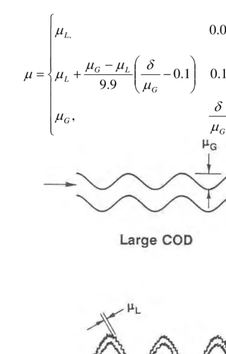
The crack morphology parameters are dependent on the crack-face surface roughness, the number of turns along the crack path, the actual flow path length, and the crack-opening displacement (Ref. 3). The surface roughness (µ) can be defined as having local (µL) and global values (µG),
see illustration in Figure 1. Likewise the number of turns (nt) is larger for a tight crack (ntL) than
a crack with a large crack opening where the turn contributes to the surface roughness. Finally there is a flow path length parameter (KG and KG+L) that may be significant for certain crack
types, e.g., IGSCC seldom grow straight through the thickness. This parameter is the actual flow path to thickness ratio, see Figure 2. This parameter accounts for the flow path being longer, particularly for tight cracks.
In Reference 3, the following equations were established using engineering judgment. For the surface roughness (µ), the following equation should be used as a function of the center crack-opening displacement (δ). This relationship is also illustrated in Figure 3.
SMiRT 16, Washington DC, August 2001 Paper # 2013
ï
ï
ï
ï
î
ïï
ï
ï
í
ì
>
<
<
÷÷ø
ö
ççè
æ
-+
<
<
=
10
,
10
1
.
0
1
.
0
9
.
9
1
.
0
0
.
0
,G G
G G
L G L
G L
m
d
m
m
d
m
d
m
m
m
m
d
m
m
(1)Figure 1 Illustration of crack-opening displacement on roughness
For the number of turns (nt), the following equation is used as a function of the center
crack-opening displacement (δ).
ï
ï
ï
ï
î
ïï
ï
ï
í
ì
>
<
<
÷÷ø
ö
ççè
æ
-+
<
<
=
10
,
1
.
0
10
1
.
0
1
.
0
11
1
.
0
0
.
0
, G tL G G tL tL G tL tn
n
n
n
n
m
d
m
d
m
d
m
d
(2)Depending on the δ (see Fig. 3), the flow path length can be defined in Equation 3, where La is
the actual length of the flow path, KG is the correction factor for global path deviations for
straightness (e.g., a crack following the fusion line of the weld), and KG+L is the correction factor
for global plus local path deviations for straightness (e.g., a crack following the grain boundaries for IGSCC).
ï
ï
ï
ï
î
ïï
ï
ï
í
ì
>
<
<
÷÷ø
ö
ççè
æ
-+
<
<
=
+ + +10
,
10
1
.
0
1
.
0
11
1
.
0
0
.
0
, G G G G G L G L G G L G aK
K
K
K
K
t
L
m
d
m
d
m
d
m
d
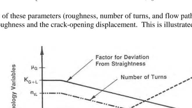
(3)All three of these parameters (roughness, number of turns, and flow path length) are related to the global roughness and the crack-opening displacement. This is illustrated in Figure 3.
The equations described above were used to investigate the effects of crack morphology on critical flaw size margins.
CRACK MORPHOLOGY PARAMTERS
Table 1 shows the crack types and their associated crack morphology variables assumed in this investigation. Note that this table was generated from the mean values of a statistical analysis conducted in Reference 3 for a variety of cracks removed from service.
Table 1 Crack Morphology parameters used in this investigation
Crack Morphology
Variable IGSCC Corrosion Fatigue Air Fatigue
mL, minch 185 347 257
mG, minch 3,150 1,595 1,325
ntL, in-1 716.3 171 51
KG 1.07 1.017 1.0
KG+L 1.33 1.06 1.0
CRACK LENGTH DETERMINATION
Calculations of crack length for a given flow rate were made using the SQUIRT (Version 2.4a) code1 (Ref. 2), which was written at Battelle Columbus and predicts leak rates using a thermal-hydraulic model derived from the Henry-Fauske model for two-phase flow.
For this comparison study, the input parameters used were:
Pipe outside diameter, inch 10.75
Pipe nominal thickness, inch 0.875
Operating temperature, F 653
Operating pressure, psig 2,250
Material TP316 – wrought with SMAW
Elastic modulus, psi 25,035,000
Yield strength, psi 19, 590
Ultimate strength, psi 72,100
Crack shape elliptical crack opening
Applied Loads
Axial force2, lbs 133,923
Bending moment3, in-lb 866,134
The crack morphology parameters in Table 1 were used with the interpolation scheme in Figure 3. In addition, the case of an air fatigue crack using only the local roughness and no number of turns was performed. The crack length calculations for a leak rate of 10 gallons per minute are shown in Table 2.
1
GE/EPRI solution with original h-functions were used in these analyses
2
Includes pressure stresses.
Table 2 Crack length results for a crack with 10 GPM leak rate
Total crack length, inch IGSCC Corrosion
Fatigue Air Fatigue
Air Fatigue, local roughness 10 gpm
flow rate 4.59 3.563 3.047 2.65
The results in Table 2 suggest that the difference in crack morphology can give a difference of up to 40 percent in the calculated crack length for this leak rate. In addition, using the incorrect parameters can produce a nonconservative margin on critical crack length. Assuming a limit load condition, the critical crack length for the case analyzed is found to be 12.85 inches. Normalizing the data shown in Table 2 with this critical crack length yields the results shown in Table 3.
Table 3 Margins on critical crack length for a variety of crack morphologies
Margin on critical crack length IGSCC Corrosion
Fatigue Air Fatigue
Air Fatigue, local roughness 10 gpm
flow rate 2.80 3.61 4.22 4.85
In making a leak-before-break assessment and using the local roughness for an air fatigue crack to analyze the behavior of an IGSCC flaw, a nonconservative factor of 1.7 on the margin for critical crack length is calculated. These data illustrate the importance of correctly characterizing the crack morphology when making LBB assessments.
SUMMARY
The results of this study illustrate the importance of defining the surface roughness and number of turns in conducting leak-rate analyses. Highly variable selections of these input parameters can significantly affect the LBB results. To avoid the arbitrary selection of these parameters, it is recommended to use the statistically determined mean values from Reference 2 for the crack type of interest. The methodology in that reference also noted that there was a
crack-opening-displacement dependence on the roughness and the number of turns. The surface roughness (µ) was defined as having a local (µL) and a global values (µG). Likewise the number of turns (nt) is
larger for a tight crack (ntL) than a crack with a large crack opening where the turn contributes to
the surface roughness. The results presented here indicate there could be a significant overprediction of the critical crack size margin if arbitrary values of the crack morphology parameters are assumed in leak rate analyses.
REFERENCES
1.) Wilkowski, G.M., and others, “Degraded Piping Program – Phase II,” NUREG/CR-4082, Vol. 8, 1989
2.) Paul, D.,D., and others, “Evaluating and refinement of Leak-Rate Estimation Models,” NUREG/CR-5128, Rev. 1, June 1994.