Effect on Efficiency Due to Variation of
Patch Height of Rectangular Microstrip Patch
Antenna
Manjari Bharati
Assistant Professor, Dept. of ECE, Dr. Sudhir Chandra Sur Degree Engineering College, Kolkata, West Bengal, India
ABSTRACT: This paper describes effect on efficiency due to variation of patch height of microstrip patch antenna. In this paper rectangular patch with probe feed technique is used. The paper describing how efficiency can vary due to change of patch height and gives a better understanding of design parameters of an antenna and their effect on return losses, efficiency and resonant frequency. Finally simulation is done using design software IE3D.
KEYWORDS:Microstrip patch antenna, probe feed, return loss, efficiency, resonant frequency, IE3D. I.INTRODUCTION
Antenna is part of a transmitting or receiving system that is designed to radiate or receive electromagnetic waves. Microstrip antenna is only one such type of antenna. A microstrip device in its simplest form is a sandwich of two parallel conducting layers separated by a single thin dielectric substrate. The upper conductor is thin metallic patch (usually Copper) which is a small fraction of a wavelength. The lower conductor is a ground plane which should be infinite theoretically. The patch and ground plane are separated by a dielectric substrate which is usually nonmagnetic. The dielectric constant of the substrate ranges from 1.17 to 25 with the loss tangent ranging from 0.0001 to 0.0004. The patch can assume any shape such as rectangular, circular, triangular, elliptical, helical, circular ring etc
.
Previously related research papers had been published using the fact that the bandwidth of a microstrip patch antenna can be increased if patch height is increased.Microstrip antennas are used where size, weight, cost, better performance, compatibility with microwave and millimeter wave integrated circuits, robustness, ability to conform to planar and non planar surfaces etc. are required. Bandwidth and efficiency of a microstrip antenna depends upon patch size, shape, substrate thickness, dielectric constant of substrate, feed point type and its location etc. For good antenna performance a thick dielectric substrate is having a low dielectric constant desirable for higher bandwidth, better efficiency and better radiation leading to a larger antenna size. In this paper effect on efficiency due to variation of patch height is described.
II.FEEDING TECHNIQUES
The two techniques available to feed or transmit electromagnetic energy i.e. induce excitation to a microstrip antenna are contracting (feeding is done directly via a connecting element such as microstrip transmission line and co-axial probe) non contracting types (like aperture coupling, electromagnetic field coupling is done to transfer power between the microstrip line and the upper conductor.
A. Microstrip Line Feed Technique
The simplest way to feed a microstrip patch is to connect a microstrip line directly to the edge of the patch. In this case both the patch and the lines are located on the same substrate. The matching between the characteristic impedance of the microstrip feed line and the patch can be done by selecting the right depth of the inset.
Fig.2 Patch antenna with microstrip line feed
B. Fringing Effect
The radiation from microstrip antenna can be found from the patch spaced of a wavelength above a ground plane. When the length of the patch is about half a wavelength long, then the radiation generates from the fringing electronic fields between the patch and the ground plane. Further, it is assumed that there is no variations of electric field along the width and the thickness of the antenna. The fringing electronic field is an effect of the electrons congregated at the surface of the conductor, especially at the edge. So that most of the radiated power is distributed from the edge of the patch.
III.MODELLING TECHNIQUES
To understand and analysis the behavior of microstrip antennas choosing model to simulate the performance is very helpful in antenna design stage. There are two types of modeling technique available.
1) Transmission line model 2) Cavity model
IV.FOUMULAS USED FOR ANTENNA DESIGNING
Here the formulas used for antenna designing are described below where W is the width of the proposed antenna, L is the length of the antenna ,ϵreff is the effectivepermittivity of the antenna.
V. DESIGNING
First a simple rectangular microstrip patch antenna has been designed using IE3D software. The design parameters are as follows
Patch length (L) =10.68mm Patch width (W) =11.86mm
Substrate thickness (h) or patch height = vary (1.5 – 3) mm Center frequency=10GHz
Dielectric constant (ԑr) = 2.2
Probe feed distance (dp) = -2 mm (from center) Probe feed radius (rp) =0.63mm
Loss tangent=0.001
Here patch height is varying from 1.5mm to 3mm. Above 3mm return loss plot is above -10dB, which is not desirable, to adjust it probe feed distance must has to vary. That is why patch height is varying from 1.5mm to 3mm keeping other parameters constant
.
The fig. below shows the design of a proposed rectangular microstrip patch antenna using IE3D software.
Fig.3 Design of rectangular microstrip patch antenna
The structure view and the 3D view of the proposed antenna using IE3D software is given below
B. 3D
View
Fig 4. Structure View and 3D view of proposed rectangular microstrip patch antenna
VI
.
EXPERIMENTAL RESULTSA. RETURN LOSS PLOT
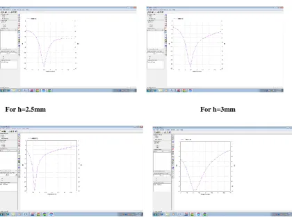
Here for different values of h such as h=1.5mm, h=2mm ,h=2.5mm, h=3mm return loss plots are given below. The response of microstrip patch antenna is good if it is below -10dB.
For h=1.5mm For h=2mm
For h=2.5mm For h=3mm
B. EFFICIENCY PLOT
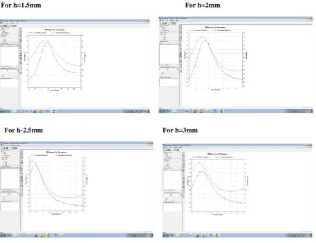
Here for different values of h such as h=1.5mm, h=2mm, h=2.5mm, h=3mm efficiency plots are given below. Efficiency decreases with increase in the patch height.
For h=1.5mm For h=2mm
For h-2.5mm For h=3mm
Fig 6.Measured Efficiency Vs Frequency plot
VII. EXPERIMENTAL DATA ANALYSIS
Antenna efficiency and radiation efficiency Vs patch height is given below as in a table. Efficiency decreases with increase in the patch height.
Table1: Patch height Vs Efficiency Patch
height(h) mm
Antenna Efficiency (%)
Radiation Efficiency (%)
VIII. CONCLUSION
The efficiency of microstrip patch antenna can be reduced by increasing the height of the antenna. This type of antenna is widely used in wireless communication system. Designing a highly efficient antenna requires a lower dielectric constant, lower patch height or substrate thickness leading to a wider bandwidth.
REFERENCES
[1] Constantine A.Balanis (2005),”Antenna Theory Analysis and Design”,John Wiley & Sons.
[2] Ramesh Garg,Prakash Bhartia,Inder Bahl & Apisak Ittipiboon, ”Microstrip Antenna Design Handbook”, Artech House.
[3] Kin-Lu Wong & Wen-Shan Chen,” Compact Microstrip Antenna with dual frequency operation”, Electronics Letters. 10th April 1997Vol.33 No.8,pp.646-647.
[4]Waterhouse,R.”Small Microstrip Patch Antenna,Electron.Lett.1995,31,(8),pp.604-605