Ning Liu1, Xian-Jun Sheng2, *, Jing-Jing Fan2, and Dongming Guo1
Abstract—We present an angular stable dual-band frequency selective surface (FSS) in this paper. By placing anchor-shaped elements with different structural parameters alongx-axis alternately within hexagonal wire grid, the proposed FSS can provide two closely spaced passbands. And the resonant frequency ratios are only 1.16 and 1.19 for TE and TM polarizations, respectively. In addition, the proposed FSS has stable frequency response under oblique incidence, and resonant frequency deviation is below 0.5% within 60◦ incident angle. An FSS prototype is fabricated and measured for further verification, and good agreements between the simulated and measured results can be observed.
1. INTRODUCTION
Frequency selective surfaces (FSSs) are periodic structures and have been widely investigated for decades. Owing to the frequency filter property, FSS has been applied to construct hybrid radomes, antenna reflectors, electromagnetic shelters, spatial filters, etc. [1]. Under some special circumstances, FSSs with multiple frequency bands are desired. Especially, in multi-frequency or multi-function communication systems, FSSs with multiple frequency bands are required to increase the system’s capacity and efficiency [2].
Motivated by this requirement, different approaches, such as periodic cell perturbation technique [3], fractal element [4], complementary structure [5], combined or multiresonant elements [6] and multilayer inductive and capacitive arrays [7], have been applied to design FSS with multiband characteristic. Recently, several FSS structures with closely spaced resonances have been proposed. A miniaturized dual-band FSS with closely spaced bands was presented in [8]. Branched cooked structure was adopted in [9] to design dual-band FSS with closely spaced frequency bands. A capacitive loaded FSS with closely spaced frequency response was presented in [10], and an FSS with closely spaced resonances based on meander lines was proposed in [11]. Identical resonant elements were adopted to construct FSS with closely spaced resonances in [12]. Nevertheless, these designs lack simultaneous angular stability as well as closely spaced resonances.
In this paper, an angular stable FSS with two closely spaced resonances is investigated. Compared with FSS structures mentioned above, the proposed FSS has smaller frequency ratio and better resonant frequency stability. Performance of the proposed FSS is demonstrated by both full-wave simulations and verification experiments.
2. FSS DESIGN AND SIMULATION RESULTS
As shown in Fig. 1, the proposed FSS is composed of anchor-shaped elements with different structural parameters arranged alongx-axis alternately within hexagonal wire grid. And the FSS layer is mounted
Received 3 July 2017, Accepted 9 August 2017, Scheduled 16 August 2017
* Corresponding author: Xian-Jun Sheng ([email protected]).
(b)
(a) (c)
Figure 1. Structure of the proposed FSS structure and its equivalent circuit model. (a) Three dimensional view. (b) The unit cell. (c) Its transmission line model.
on one side of a dielectric substrate. Due to the difference in anchor-shaped elements, two resonant paths will be provided, and then two stop-bands are produced.
According to the equivalent circuit theory [13], frequency filter property of the proposed FSS can be simply analyzed via its equivalent circuit model. As shown in Fig. 1(c), the hexagonal wire grid can be modelled as an inductor L0, and the anchor-shaped elements with different structural parameters
can be depicted by two series LC resonators (L1-C1 and L2-C2), respectively. As for the dielectric
substrate, it can be modelled by a short transmission line, where Z0 is the wave impendence in free
space, andZT is the wave impendence in the dielectric substrate. As indicated in Fig. 1(c), there will be two stopbands, if the two seriesLC resonators (L1-C1 and L2-C2) resonate. Obviously, a passband will
be formed between the two transmission zeroes, which are produced by the two series LC resonators. Meanwhile, due to the existence of the equivalent circuit inductor L0, an additional passband will be
produced by the first seriesLC resonator (L1-C1) and the inductorL0. Based on the discussion above,
the proposed FSS can produce two passbands separated by two transmission zeroes.
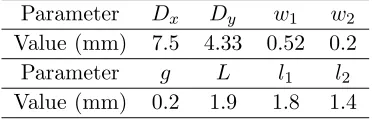
Table 1. Structural parameters of the proposed FSS element.
Parameter Dx Dy w1 w2
Value (mm) 7.5 4.33 0.52 0.2
Parameter g L l1 l2
Value (mm) 0.2 1.9 1.8 1.4
To verify the performance of the proposed FSS, simulations by commercial software CST Microwave Studio are carried out. Structural parameters of the proposed FSS layer are set and shown in Table 1. The FSS layer is mounted on an F4B-2 substrate, whose dielectric permittivityεr = 2.65, tangent loss tanδ = 0.002, and thicknessh= 1 mm.
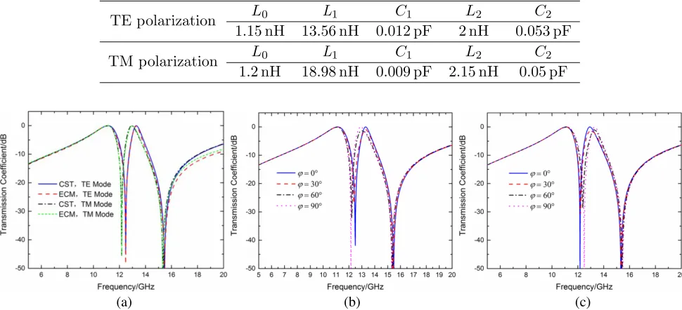
Firstly, transmission coefficients of the proposed FSS at normal incidence with different polarizations are calculated and shown in Fig. 2. Based on the curve-fitting technique in [14], the frequency responses of the equivalent circuit model (ECM) obtained by ADS are also shown in Fig. 2(a) for comparison. The parameters of the lumped elements are listed in Table 2. As observed in Fig. 2, the proposed FSS can provide two close passbands separated by two transmission zeroes. For TE polarization, resonant frequencies of the two passbands are fp1 = 11.13 GHz and fp2 = 13.29 GHz,
respectively. And the transmission zeroes occur atfz1 = 12.48 GHz andfz2= 15.46 GHz, respectively.
For TM polarization, the two passbands operate at fp1 = 11.08 GHz and fp2 = 12.92 GHz, which are
separated by two transmission zeroes occurring at fz1 = 12.17 GHz andfz2= 15.34 GHz. As indicated
Table 2. Lumped-element parameters in the equivalent circuit model.
TE polarization L0 L1 C1 L2 C2
1.15 nH 13.56 nH 0.012 pF 2 nH 0.053 pF
TM polarization L0 L1 C1 L2 C2
1.2 nH 18.98 nH 0.009 pF 2.15 nH 0.05 pF
(b)
(a) (c)
Figure 2. Transmission coefficient of the proposed FSS at normal incidence (a) With polarization angleϕ= 0◦. (b) With different polarization angles for TE polarization. (c) With different polarization angle for TM polarization.
(b) (a)
(c) (d)
(a) (b)
Figure 4. Transmission coefficients of the proposed FSS structure under oblique incidence. (a) TE polarization. (b) TM polarization.
are produced. As observed, the first transmission zero is mainly produced by the anchor-shaped element with longer legs, and its equivalent circuit parameters areL1 andC1. Meanwhile, the equivalent circuit
parameters L2 and C2 are mainly produced by the anchor-shaped element with shorter legs, which
will form the second transmission zero operating at fz2. As indicated in Fig. 3, due to the
anchor-shaped element structure design, resonant lengths under TE and TM polarization are different. This difference in resonant length under different polarizations will lead to resonant frequency shift of the two transmission zeroes. Then, as observed in Fig. 2(b) and Fig. 2(c), different frequency responses under different polarization angles will be obtained.
Based on the discussion above, resonant frequencies of the transmission zeroes are mainly affected by the two anchor-shaped elements, and due to the difference in resonant length under different polarizations, frequency response of the designed FSS is sensitive to polarization angles. Meanwhile, due to the hexagonal wire grid structure design, an equivalent circuit inductor will be produced. Then, combined with the anchor-shaped element, the proposed FSS structure can provide two passbands, in which the first passband is mainly affected by the wire grid and the anchor-shaped element with longer legs, and the second one is mainly affected by the two anchor-shaped elements with different lengths of legs. Hence, resonant frequency and bandwidth of the passband can be changed by adjusting the corresponding structural parameters. In addition, polarization sensitivity can be compensated by decreasing the difference in resonant lengths. Based on this idea and the surface current distribution, difference in resonant lengths under TE and TM polarizations can be compensated by adopting the modified anchor-shaped element, in which lengths of the three legs are different. By properly designing lengths of the three legs, same resonant lengths under TE and TM polarizations will be formed. Then, lower polarization sensitivity will be obtained.
Subsequently, transmission coefficients of the proposed FSS at oblique incidence with different polarizations are simulated and shown in Fig. 4. It can be observed that resonant frequency of the two passbands maintains well at oblique incidence. For TE polarization, when the incident angle reaches 60◦, resonant frequency deviations of the two passbands are only 0.34% and 0.28%, respectively. As for TM polarization, resonant frequency deviations are only 0.48% and 0.18%.
Finally, to verify the performance of the proposed FSS, comparisons with similar FSS structures in previous works are carried out. It can be observed from Table 3 that compared with other similar FSS structures, the proposed FSS has smaller resonant frequency ratio and better angular stability. And resonant frequency ratios of the proposed FSS are as low as 1.16 and 1.19 for TE and TM polarizations, respectively.
3. EXPERIMENTAL VERIFICATION
FSS structure proposed
TE :1.19
TM:1.16 Maximum shift of 0.5% from 0
◦ to 60◦
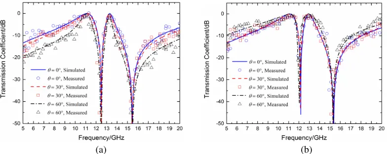
microwave anechoic chamber with the free-space measurement system composed of two horn antennas connected to a network analyzer (Agilent N5230A). In the experiment, transmission coefficients are measured firstly without the FSS prototype, and then the measured results are adopted to modify the measured transmission coefficients with the FSS prototype. To ensure that the incident wave is plane wave, the transmitting antenna is placed about 3 m away from the fabricated FSS prototype, and the distance between the receiving antenna and FSS prototype is about 0.5 m.
The measured transmission coefficients of the fabricated FSS under different incident angles, together with the simulated ones, are shown in Fig. 6. It can be observed that the measured results agree with the simulated ones very well. And the frequency filter property maintains well under oblique
Figure 5. Photograph of the fabricated miniaturized FSS.
(a) (b)
incidence, which demonstrates the validity of the proposed FSS. Note that there are unexpected ripples in the measured transmission coefficient curves. The differences are mainly caused by the errors with measuring systems, especially the edge diffraction of the fabricated FSS prototype.
4. CONCLUSION
In this paper, an angular stable FSS with two closely spaced passbands are proposed. Resonant frequency ratios are only 1.16 and 1.19 for TE and TM polarizations, respectively. In addition, resonant frequency deviation is below 0.5% at oblique incidence within 60◦ incident angle. Consequently, compared with other FSS designs, the proposed one is a balanced design considering the angular stability as well as closely spaced resonances simultaneously. Finally, the proposed FSS is fabricated and measured, showing satisfactory agreements with the simulation results.
ACKNOWLEDGMENT
This work was supported by the National Natural Science Foundation of China under grant 51575081 and the Fundamental Research Funds for the Central Universities under grant DUT17ZD304.
REFERENCES
1. Munk, B. A., Frequency Selective Surfaces: Theory and Design, Wiley, New York, 2000.
2. Yan, M., et al., “A tri-band, highly selective, bandpass FSS using cascaded multilayer loop arrays,” IEEE Trans. Antennas Propag., Vol. 64, No. 5, 2046–2049, 2016.
3. Hill, R. A. and B. A. Munk, “The effect of perturbating a frequency selective surface and its relation to the design of a dual-band surface,” IEEE Trans. Antennas Propag., Vol. 44, No. 3, 368–374, 1996.
4. Werner, D. H. and D. Lee, “Design of dual-polarised multiband frequency selective surfaces using fractal elements,” Electron. Lett., Vol. 36, No. 6, 487–488, 2000.
5. Hu, X.-D., et al., “A miniaturized dual-band frequency selective surface (FSS) with closed loop and its complementary pattern,”IEEE Antennas Wireless Propag. Lett., Vol. 8, 1374–1377, 2009. 6. Wu, T. K. and S. W. Lee, “Multiband frequency selective surface with multi-ring patch elements,”
IEEE Trans. Antennas Propag., Vol. 42, No. 11, 1484–1490, Nov. 1994.
7. Gao, M., S. M. A. M. H. Abadi, and N. Behdad, “A dual-band, inductively-coupled miniaturized-element frequency selective surface with higher-order bandpass response,” IEEE Trans. Antennas Propag., Vol. 64, No. 8, 3729–3734, 2016.
8. Chiu, C. N. and W. Y. Wang, “A dual-frequency miniaturized-element FSS with closely located resonances,” IEEE Antennas Wireless Propag. Lett., Vol. 12, 163–165, 2013.
9. Sivasamy, R. and M. Kanagasabai, “A novel dual-band angular independent FSS with closely spaced frequency response,” IEEE Microw.Wireless Compon. Lett., Vol. 25, No. 5, 298–300, 2015. 10. Xu, R., H. Zhao, Z. Zong, and W. Wu, “Dual-band capacitive loaded frequency selective surfaces with close band spacing,” IEEE Microw. Wireless Compon. Lett., Vol. 18, No. 12, 782–784, Dec. 2008.
11. Ghosh, S. and K. V. Srivastava, “An angularly stable dual-band fss with closely spaced resonances using miniaturized unit cell,”IEEE Microw.Wireless Compon. Lett., Vol. 27, No. 3, 218–220, 2017. 12. Huang, F. C., C. N. Chiu, et al., “Very closely located dual-band frequency selective surfaces via
identical resonant elements,”IEEE Antennas Wireless Propag. Lett., Vol. 14, 414–417, 2015. 13. Costa, F., A. Monorchio, and G. Manara, “Efficient analysis of frequency selective surfaces by a