How to cite this paper: Peng, L. and Yang, L.L. (2014) Low-Complexity LDPC-Coded USTM Noncohereny MIMO Receivers. Open Access Library Journal, 1: e550. http://dx.doi.org/10.4236/oalib.1100550
Low-Complexity LDPC-Coded USTM
Noncohereny MIMO Receivers
Li Peng, Lingling Yang
Wuhan National Laboratory for Optoelectronics, Department of Electronics and Information Engineering, Huazhong University of Science and Technology, Wuhan, China
Email: [email protected]
Received 10 July 2014; revised 15 August 2014; accepted 20 September 2014 Copyright © 2014 by authors and OALib.
This work is licensed under the Creative Commons Attribution International License (CC BY). http://creativecommons.org/licenses/by/4.0/
Abstract
This paper proposes a scheme of combining low-density parity check (LDPC) code with unitary space time modulation (USTM) for noncoherent multiple-input-multiple-output (MIMO) transmit- ter and receiver over Rayleigh block fading and additive white Gaussian noise (AWGN) channel. The main aim is to design the low complexity coded noncoherent MIMO receiver which is com-pletely dependent on the structural feature of unitary space-time matrix without sending the pilot symbol at the transmitter and estimating the channel state information at the receiver. Consider-ing soft information required by belief-propagation (BP) iterative decoder of LDPC code, we de-duce a maximum a posteriori probability (MAP) demodulating algorithm using a special USTM based on the sine-cosine function. A novel dual-demodulator is conceived for decreasing the com-putational complexity of this MAP demodulator. Furthermore, the iterative feedback scheme be-tween MAP demodulator and BP decoder is introduced and its modified parameter scheme is con-sidered for further improving performance of the dual-demodulator. Comparing with uncoded USTM, our LDPC-coded USTM MIMO receiver can obtain about 17 dB coding gain at 10−6 BER.
Keywords
Unitary Space-Time Modulation (USTM), Log-Likelihood Ratio (LLP), Maximum a Posteriori Probability (MAP), Demodulating Algorithm, Iterative Feedback, Low-Density Parity-Check (LDPC) Code
Subject Areas: Information and Communication Theory and Algorithms, Mobile and Portable Communications Systems
1. Introduction
OALibJ | DOI:10.4236/oalib.1100550 2 September 2014 | Volume 1 | e550
receive antennas in fading channels, which know the perfect channel state information (CSI) at the receiver, is appealing for its capacity of growing as min
{
M N,} (
log SNR)
at high signal-to-noise ratios (SNRs) [1] [2], which provides higher data rate than single-input single-output (SISO) system. But the practical situation is that the perfect CSI may be unavailable at the receiver, which results in the difficulty of coherent demodulation. An alternative is noncoherent MIMO systems proposed by Hochwald et al. in [3] [4] which neither transmitter nor receiver knows CSI. Its capacity of a block-fading channel with coherent interval T grows as(
)
(
)
* *
1 log
M −M T SNR with M*=min
{
M N T, , 2}
at high SNR [3] [5], which is(
*)
1−M T times less than that of coherent MIMO system but it has potential practical demodulating scheme. In recent years, two studying directions of noncoherent MIMO modulating/demodulating system are widely investigated. One is that transmitters in [6]-[9] send both pilot symbol and data symbol in a coherent interval T and receivers first mate CSI by using the pilot symbol and then coherently demodulates the data information by means of the esti-mated CSI, which is called pilot symbol-assisted modulation (PSAM). The other is that transmitters send iso-tropically distribution unitary signals generated by unitary space time modulation (USTM) in [3] [4] and rece-ives complete noncoherently demodulations based on the maximum likelihood (ML) by means of the structure features of an unitary space time matrix [10]-[12]. The drawback of the former is that sending pilot symbol at transmitter needs to consume channel bandwidth resource and channel estimation at receiver increases time-de- lay of system and leads to performance loss by channel estimation error. The drawback of the latter is that the ML demodulating algorithm based on unitary space-time matrix requires the calculation of constellation point traversal which leads to high complexity, especially for the large size of constellation.
At the present, many improved strategies of the above-mentioned drawbacks for two schemes are paid atten-tion to in communicaatten-tion field. For examples, [7] [9] studied the schemes of information-bearing pilots which is likely to mitigate the bandwidth consumption of pilots, while [12] [13] involved the research of reducing the complexity of the ML algorithm based on USTM. As the drawback of time-delay formed by the channel estima-tion in MIMO systems with PSAM or informaestima-tion-bearing PSAM scheme is inevitable, so we focus on the de-sign of the MIMO system based on complete unitary space-time matrix which need not estimate CSI. The key problem is to find the simple demodulating algorithm at receiver. It appears that few research findings of the simplified demodulating algorithm are published, but we can still catch a glimpse of two developing directions, such as constructing the special structural unitary matrix set which can generate simple demodulating algorithm
[11] [12] and designing a general simplified demodulating algorithm for arbitrary unitary constellation [13].
The paper [11] provides a noncoherent unitary constellation
{ }
10 L l l
− =
Φ in which the lth unitary space time
matrix has aspect Φl =sin
(
πl L)
⋅IM cos(
πl L)
⋅IMT M†× for l=0,1,,L−1, where L denotes the sizeof constellation and IM is the M×M identity matrix, and we call it the USTM based on the sine-cosine function, the SC-USTM for short. Up to now, only SC-USTM can generate the simplest demodulation algorithm based on the maximum likelihood (ML) whose complexity is O MN
(
)
which is completely independent of the size of constellation L and coherent interval T, unlike the other existing USTM schemes whose simple de-modulation algorithms has O MNTL(
)
complexity, where L<L denotes those constellation points which take part in the calculation after simplifying the ML demodulating algorithm [12] [13]. Because of this, this pa-per will use the SC-USTM to construct the coded USTM noncoherent MIMO system which is expected to achieve the lowest demodulating complexity under the condition of taking no account of CSI.It is known from [3] that the capacity-achieving USTM is fit for the region of high SNR or when TM . In order to make the MIMO system also achieve the channel capacity in the low-SNR region, as well as for non-coherent block fading channels with small T values, it is widely acknowledged that channel coding should be considered in MIMO system. In recent few years, the noncoherent MIMO systems of combining error correcting codes with space-time modulation have been noted by the communication system designers. Multiple articles [7] [14]-[19] investigated the diversified concatenated schemes of combining Turbo code with USTM technique from different perspectives. In [16], USTM technique is introduced to the trellis code modulation (TCM) schemes. A convolutional coded sequence was first transformed into an interleaved sequence and then mapped the USTM signal matrix in [17]. The performance bound for the LDPC-coded USTM is investigated in [18], and in [6], a concatenated scheme of combining turbo-like code with pilot-assisted USTM was discussed.
OALibJ | DOI:10.4236/oalib.1100550 3 September 2014 | Volume 1 | e550
paper is a development of [20] through the following jobs. First, we deduce the simplifying MAP demodulating algorithm by using the structural feature of the SC-USTM based on the original MAP algorithm in [20], see Section III. For reducing the calculated amount of constellation point traversal in the MAP demodulating algo-rithm, we create the novel dual-demodulator which has nothing to do with the size of constellation L and co-herent interval T, and has only linear complexity in all antennas MN, see Section IV. In order to improve performance, we introduce iterative feedback mechanism between the MAP demodulator and the BP iterative decoder, and discuss the scheme of modifying the feedback parameter, in Section V. Section VI gives the analy-sis of complexity. Conclusions are drawn in Section VII.
2. LDPC-CODED SC-USTM System Model
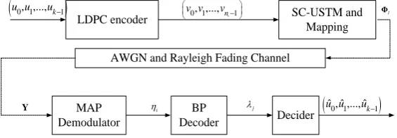
Consider a channel model with M transmit and N receive antennas. The channels between transmit and receive antenna pairs are Rayleigh block fading channels and independent of each other. The fading coefficients remain constant for a block of T symbol intervals and change independently from one block to another. Figure 1
gives the specific LDPC-coded SC-USTM system model operating on the above channel.
The transmitter contains two parts: LDPC encoder and SC-USTM modulator. An information sequence
(
u u0, 1,,uk−1)
is first encoded into a codeword sequence(
v v0, ,1,vnc−1)
by using the LDPC code with ratec c
R =k n , where k and nc denote respectively the length of information bits and codeword. Taking in turn
2 log
a= L bits from the LDPC-coded sequence
(
0, ,1 , 1)
c
n
v v v − , we can construct the coded mapping se-quence (CMS) zl =
(
z z0, ,1 ,za−1)
for l=0,1,,L−1, where L denotes the size of constellation. There are2a=L distinct CMSs which form a set
{ }
10 L l l
− =
z .
We require that the transmit signal matrix (TSM) Xl = TΦl is designed as a T×M unitary matrix that satisfies †
l l =IM
Φ Φ for l=0,1,,L−1, and L transmit signal matrices form a unitary space-time constel- lation
{
}
10 L l
l
T −
=
Φ , where L=2a=2R Tm which gives the code rate
(
)
2
log
m
R = L T (bit/ channel use). Here,
let
[ ]
⋅† denote real transpose matrix and[ ]
⋅∗ denote complex conjugate transpose matrix.Suppose Xl is transmitted via the channel shown as Figure 1, then the T×N received signal matrix is:
l l
T
M M
ρ ρ
= + = +
Y X H W ΦH W (1)
where H is a M×N channel transfer matrix and W is a T×N additive white Gaussian noise (AWGN) matrix, both of whose entries obey CN
( )
0,1 distribution. The normalization factor ρT M of (1) ensures that the average signal noise ratio (SNR) at each receive antenna is ρ.The receiver also contains two parts: noncoherent demodulator and belief-propagation (BP) decoder. Y is first demodulated as the soft information ηi
(
i=0,1,,nc−1)
by the MAP demodulator and then nc soft in-formation values 0, 1, , 1c
n
η η η − are fed into the BP decoder in parallel. The BP decoder outputs λi,
0,1, , c 1
i= n − (or λj, j=0,1,,k−1) which are computed by means of the BP iterative decoding algo-rithm of the LDPC code. Finally, k soft information values λ λ0, 1,,λk−1 are fed to the decider and the de-
LDPC encoder SC-USTM and
Mapping
AWGN and Rayleigh Fading Channel
BP Decoder MAP
Demodulator Decider
(
u u0, ,...,1 uk−1)
(
u uˆ ˆ0, ,...,1 uˆk−1)
0, ,...,1 nc1
v v v −
Φl
Y ηi λj
Figure 1. Noncoherent MIMO transmitter and receiver for the LDPC-coded
[image:3.595.172.455.592.690.2]OALibJ | DOI:10.4236/oalib.1100550 4 September 2014 | Volume 1 | e550
cider outputs the decoded information sequence
(
u uˆ0,ˆ1,,uˆk−1)
in parallel. So far, a general encoding/mod- ulating and demodulating/decoding noncoherent MIMO system without regard to channel estimation has been established. The spectral sufficiency of the MIMO system is R=R Rc m =k(
log2L)
n Tc (bit/channel use).In transmitter, the mapping from a CMS
{ }
10 L l l l
− =
∈
z z to a TSM
{
}
10 L l l l T − = ∈
X Φ will be designed by consi- dering synthetically the several factors, such as construction of transmit signal matrix, model of demodulating algorithm and model of distance measures.
We designed three MIMO systems according to different demodulating algorithm. The first system directly uses the MAP demodulating algorithm as demodulator in receiver and its transmitter adopts the natural mapping
scheme. The so-called “natural mapping” means that L binary CMSs
{ }
1 0 L l l− =
z are ranked according to the
natural order of decimal system which is a relationship of one-to-one correspondence with the natural order of
the SC-USTM constellation
{
}
{
(
)
(
)
}
1
1 †
0 0
sin π cos π
L L
l M M T M
l l
T T l L l L
− −
×
= = ⋅I ⋅I =
Φ . The second system
uses the presented dual demodulating scheme as demodulator in receiver and its mapping in transmitter is the
Gray code of the set
{ }
10 L l l
− =
z . This mapping scheme means that any two adjacent CMSs in this Gray code differ
in only one bit and each of L CMSs based on the rank of Gray code is still one to one match with the natural
order of the SC-USTM constellation, i.e., l=0,1,,L−1. The hardware design and implementation of the Gray mapping, superficially at least, is more troublesome than that of the natural mapping. But late on, we will observe that the Gray mapping produces the benefit for reducing the complexity of dual demodulators by a large margin. The third system combines the presented dual demodulating scheme with the BP iterative decoding al-gorithm of the LDPC code to construct an iterative feedback system.
We claim to design a practical LDPC-coded SC-USTM system. Here the LDPC codes can be any available structure. In our simulation tests, the irregular QC-LDPC codes in IEEE 802.16e Standard [21] is selected as the outer code and the LDPC decoder uses the standard BP algorithm based on the bitwise reliability. The detail de-scription of the LDPC encoder and decoder is omitted for brevity.
3. The SC-USTM Map Demodulator
In order to perform the decoding algorithm of the LDPC code, we need to get the LLR values of message bits from the demodulator of the SC-USTM, which should be analogous to the LLR of the observation from a BPSK demodulator over an AWGN channel. We do not repeat in detail the derivation of the general MAP demodulat-ing algorithm based on USTM [7] [14] [15], but only derive the simplified MAP demodulating algorithm based on the structural SC-USTM first presented by [11] and then used by [19].
Let
τ
=0,1,,a−1 denote the index of binary code bit in any of L CMSs. We separate the set{ }
10 L l l − = Φ
into two subsets 1
τ
Φ and 0
τ
Φ , similarly the index l=0,1,,L−1 of the set
{ }
10 L l l
− =
z is also separated into
two index subsets lτ1 and lτ0, lτ1 + lτ0 =L, where Φτ1 denotes the set of such matrix and lτ1 of such index that the τ th bit of the CMS zl is 1 and 0
τ
Φ and 0
lτ respectively the set of such matrix or index that the τth
bit of zl is 0 for
τ
=0,1,,a−1. For any transmit signal matrix Φl and any receive signal matrix Y , the LLR of the τ th bit in zl, i.e., the general MAP demodulating algorithm [14] [15] of USTMis given by(
)
10 , , , 1 exp 1
Pr 1 |
log log
Pr 0 | 1
exp 1 l l l l l
i i l
l l l tr M T z z z z tr M T τ τ τ τ τ ρ η η ρ ∗ ∗ ∈ ∗ ∗ ∈ = + = = = = = +
∑
∑
Y Y Y Y Y Y Φ Φ Φ Φ Φ Φ Φ Φ (2)where zl,τ denotes the binary value of the τ th bit in the CMS zl and zi denotes the binary value of the i
th bit in codeword with length nc, and both are one-to-one.
We find that (2) can be simplified from two directions. First, it contains the multiplication of four T×M
(
M =N)
complex matrices, and then, it requires all L constellation point matrices to taking part in theOALibJ | DOI:10.4236/oalib.1100550 5 September 2014 | Volume 1 | e550
real numbers by using the structural feature of the SC-USTM. The further simplified scheme of reducing the number of matrices of (2) will be discussed in the next section.
According to the structural feature of the unitary space time matrix of SC-USTM, we can know that
(
)
(
)
† †
† †
sin π cos π
l M M M M
T M× l L l L
=S C = ⋅I ⋅I
Φ is a real matrix of satisfying †
l l=IM
Φ Φ , where
0,1, , 1
l= L− and T =2M , and M ≥2 and N are any positive integer. For convenience of mathematical process, suppose the corresponding receive signal matrix has the form Y = SN* C*N∗, where SN and CN
are two M×N matrices in which all complex elements eimn
mn
a θ and ei mn
mn
b ϕ denote the receive signals from N receive antennas during T=2M for m=0,1,,M−1 and n=0,1,,N−1. Substituting Φl and Y into (2), by means of three types of triangle function transforms 2 cos sinφ φ=sin 2φ,
(
)
2
sin φ= −1 cos 2φ 2 and cos2φ= +
(
1 cos 2φ)
2, we get(
)
(
)
(
)
(
)
(
)
(
)
(
)
(
)
(
)
(
)
(
) (
)
† * ** 2 * 2
* *
sin π
sin π cos π
cos π
sin π cos π
sin π cos π
l l
N M
N N M M
N M
NM MN NM MN
NM MN NM MN tr
l L
tr l L l L
l L
tr l L tr l L
tr l L l L
∗ ⋅ = ⋅ ⋅ ⋅ = + + + Y Y S I
S C I I
C I
S S C C
S C C S
Φ Φ
(
) (
) (
) (
)
(
)
(
)
(
)
( )
( )
( )
( )
(
)
(
) (
)
(
)
(
)
* * * * * *2 2 2 2
1 1 1 1 1 1 1 1
1 1
cos 2π
2 2
sin 2π 2
cos 2π
2 2
2 cos sin 2π
cos 2π 2 sin 2π
NM MN NM MN NM MN NM MN
NM MN NM MN
N M N M N M N M
mn mn mn mn
n m n m n m n m
N M
mn mn mn mn
n m
tr tr tr tr
l L
tr
l L
a b b a
l L
a b l L
l L l L
θ ϕ
α β γ
= = = = = = = = = = + − = + + + + − = + + − = + +
∑∑
∑∑
∑∑
∑∑
∑∑
S S C C C C S S
S C C S
where
( )
2( )
21 1 1 1
2
N M N M
mn mn
n m n m
b a α = = = = = −
∑∑
∑∑
,( )
2( )
21 1 1 1
2
N M N M
mn mn
n m n m
b a β = = = = = −
∑∑
∑∑
,(
)
1 1 cos N Mmn mn mn mn
n m
a b
γ θ ϕ
= =
=
∑∑
− .We rewrite the LLR of (2) as follows.
(
)
(
)
(
)
(
)
(
)
1 1 0 0 , , ,cos 2π sin 2π exp
1 log
cos 2π sin 2π exp
1
l l l L
i i l
l l l L
l L l L
M T
z z
l L l L
M T
τ τ
τ τ
τ
α β γ
ρ η η
α β γ
ρ ∈ ⊂ ∈ ⊂ + + + = = = + + +
∑
∑
(3)We call the expression (3) the SC-USTM MAP demodulating algorithm.
4. Dual-Demodulator of SC-USTM
OALibJ | DOI:10.4236/oalib.1100550 6 September 2014 | Volume 1 | e550
take part in the calculation of (3), which results in the calculated amount of L exponents. We create the dual
demodulating scheme in order to decrease the exponent operations, or eliminate as many matrices taking part in the calculation of (3) as possible. The basic ideal is that the first demodulation uses the maximum likelihood (ML) algorithm of SC-USTM and the second demodulation uses the SC-USTM MAP algorithm presented in the above section, and Figure 2 gives the block diagram of the MIMO system based on the dual-demodulator.
4.1. The SC-USTM ML Demodulating Algorithm
It is necessary to explore the basic principle and the calculated complexity of the SC-USTM ML demodulating algorithm with a perspective different from [11]. For arbitrary positive integer M ≥2, N and T =2M, un-der the condition of the transmit signal matrix being
(
)
(
)
† †
† † sin π cos π
l=SM CM = l L ⋅IM l L ⋅IM
Φ , we suppose that the T×N receive signalmatrix has
the form of * *
N N
∗
=
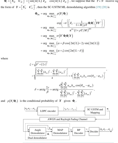
Y S C , then the SC-USTM ML demodulating algorithm [19] [20] is
{ }
(
)
{ }(
)
{ }(
)
{ }(
(
)
(
)
)
{ }(
(
)
)
1 0 1 0 1 0 1 0 1 0 † † † † arg max 1 exp 1 arg max π 1 arg maxarg max cos 2π 2 sin 2π
arg max cos 2π
L l l l
L l l l
L l l l
L l l l
L l l l
ML l
T l l
MN TN l l p tr M T T M tr
l L l L
l L
ρ ρ
α β γ
α ξ δ
− = − = − = − = − = ∈ ∈ ∈ ∈ ∈ = − − + = + = = + + = + − Y I YY Y Y Φ Φ Φ Φ Φ Φ Φ Φ Φ Φ Φ Φ Φ Φ
Φ Φ (4)
where
( )
( )
( )
(
)
2 2 2 2 2 2 1 1 1 11 1
2
4 cos
4
N M N M
mn mn N M
n m n m
mn mn mn mn
n m
b a
a b
ξ β γ
θ ϕ = = = = = = = + − = + −
∑∑
∑∑
∑∑
,(
)
( )
( )
1 1 2 21 1 1 1
4 cos
2
arctg arctg
N M
mn mn mn mn n m
N M N M
mn mn
n m n m
a b
b a
θ ϕ
γ δ
β = =
= = = =
−
= =
−
∑∑
∑∑
∑∑
, (5)and p Y
(
Φl)
is the conditional probability of Y given Φl.LDPC encoder SC-USTM and
Mapping
AWGN and Rayleigh Fading Channel
Angle Demodulator BP Decoder MAP Demodulator Decider
(
u u0, ,...,1 uk−1)
(
u uˆ ˆ0, ,...,1 uˆk−1)
0, ,...,1 nc1
v v v −
Φl
Y ηi λj
Y
ˆ
l
Φ Dual demodulator
Figure 2. Noncoherent MIMO transmitter and receiver for the LDPC-coded SC-
[image:6.595.84.480.219.698.2]OALibJ | DOI:10.4236/oalib.1100550 7 September 2014 | Volume 1 | e550
If making cos 2
(
πl L−δ)
=1 for (4), then the likelihood probability p Y(
Φl)
can achieve the maximum value. From relationship cos 2(
πl L−δ)
=1, we can solve the following sequence number of constellation points by plugging (5) into (4):(
)
(
)
( )
( )
(
)
1 1
2 2
1 1 1 1
2π 0.5 mod
4 cos
arctg 0.5 mod
2π
N M
mn mn mn mn n m
N M N M
mn mn
n m n m
l L L
a b L
L
b a
δ
θ ϕ
= =
= = = =
= +
−
= +
−
∑∑
∑∑
∑∑
(6)
where x denotes the largest integer that does not exceed x, modL denotes that l is a positive integer and its range is 0≤ ≤ −l L 1. The function of taking the floor x may introduce the following error. If the fractional part of δL 2π is less than 0.5, then the demodulating error of δL 2π = l is small, or l is the correct sequence number of the demodulated signal matrix; if the fractional part of δL 2π is larger than 0.5, then the demodulating error of δL 2π = l is large. For relieving the error, we make δL 2π 0.5+ replace δL 2π. Let l be the demodulated sequence number. If the fractional part of δL 2π is less than 0.5, then δL 2π 0.5+ =l; if the fractional part of δL 2π is larger than 0.5, then
2π 0.5 1
L l
δ
+ = +
. We call (6) the SC-UATM ML demodulating algorithm, or the angle demodulator for short.
Here, we give the complexity analysis of the angle demodulator. From (6), we can know that
, , ,
mn mn mn mn
a b θ ϕ are the known parameters provided by all complex elements in receive signal matrix. Once the values of L M N, , are given, the calculating amount of (6) is 4MN+2 real additions and 4MN+4 real multiplications, plus one arc tangent. The SC-UATM ML demodulating algorithm is independent of the size of constellation L, the coherent time T and the date rate Rm and its complexity is very low and a linear rela-tionship with M and N, i.e., the demodulating complexity is O MN
(
)
.4.2. The Dual Demodulator of SC-USTM
We observe the MAP demodulating algorithm of the SC-USTM in (3) and discover that the summing expression in numerator and denominator requires all L constellation points to take part in the calculation of (3). For re-ducing the number of constellation points of taking part in the calculation of (3), we create the dual demodulator which is wished to decrease the calculated quantity from L points to ˆL<L points, where ˆL denotes the number of those constellation points of taking part in the calculation of (3) after reducing L. Let
{ }
Lˆ denote the set of index values of ˆL signal matrices.Our basic thought is: firstly, demodulate a proximate signal matrix ˆΦl by exploiting the angle demodulator of the SC-USTM; then make the demodulated ˆΦl (or l) as the central point and select three points, five points, seven points and so on, i.e., l l, ±1,l± ⋅⋅⋅∈2,
{ }
Lˆ which are viewed as those points of taking part in calculation of (3) until they achieve some acceptable performance.The angle demodulator of (6) may lead to the error toward two directions. This is that the lth transmit signal matrix is more likely to be improperly demodulated as the l−1th matrix or the l+1th matrix. According to this feature, we choose the Gray code to design the coded mapping sequence. This mapping scheme that the se-quence number l=0,1,,L−1 of transmit signal matrix has a one-to-one correspondence with the codeword of the coded mapping sequence based on Gray code can make the demodulating error achieve a degree as small as possible.
Let ˆL=3, 5, 7 points which respectively corresponds to three cases: Lˆ=3 for L=16, Lˆ=5 for L=32,
ˆ 7
L= for L≥64. When l lτ τ1, 0 ⊆
{ }
Lˆ and l1 l0 Lˆτ + =τ , then (3) can be modified as follows
(
)
(
)
{ }
(
)
(
)
{ }
1 1
0 0
ˆ ,
ˆ ,
cos 2π sin 2π exp
1 log
cos 2π sin 2π exp
1
l l l L
i
l l l L
l L l L
M T
l L l L
M T
τ τ
τ τ
α β γ
ρ η
α β γ
ρ
∈ ⊆
∈ ⊆
+ +
+
=
+ +
+
∑
∑
(7)
OALibJ | DOI:10.4236/oalib.1100550 8 September 2014 | Volume 1 | e550
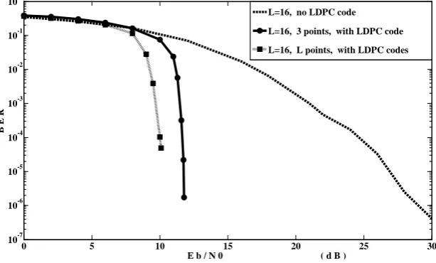
We did the simulation experiments for three demodulating algorithms, i.e., the angle demodulator of (6), the SC-USTM MAP demodulating algorithm of (3) and the simplified MAP demodulating algorithm of (7) com-bining with the dual demodulator. Figure 3 gives the comparison results of their performance curves. The expe-riment conditions are setup as follows. The structural parameters of the SC-USTM are M = N = 2, T = 2M = 4, and the size of constellation is L=16. The structural parameters of the QC-LDPC codes from IEEE 802.16e Standard are code rate Rc =1 2 and code length nc =2304.
In Figure 3, the dash line shows the performance of the angle demodulator without the LDPC code, this is
that the MIMO system with the SC-USTM and its angle demodulator of (6) operates in high-SNR region which is 28 dB at a BER of 2.5 10× −6 and at the data rate which is R=Rm=
(
log2L T)
=1 (bit/ channel use).The dot line with the square symbol shows the performance of the LDPC coded SC-USTM MIMO system of combining the SC-USTM MAP demodulating algorithm of (3) with the BP decoder at the receiver, and the LDPC coded SC-USTM MIMO system improves the performance about 15 dB at the BER level of 1.0 10× −4, compared to the performance of the uncoded SC-USTM MIMO system, and the data rate of this MIMO system is R=R Rm c = ×k
(
log2L)
nc× =T 0.5 (bit/ channel use).The solid line with circle symbol shows the performance of the LDPC coded SC-USTM MIMO system with the dual demodulator. This scheme needs only three points Lˆ=3 take part in the calculation of (7) and im-proves the performance about 17.0 dB at the BER level of 1.0 10× −6, compared to the performance of the un-coded SC-USTM MIMO system, but deteriorates the performance about 1.0 dB at the BER level of 1.0 10× −4, compared to the performance of the SC-USTM MAP demodulating algorithm with L=16 points of (3).
Therefore, the simplified MAP of (7) and the general MAP of (3) for the SC-USTM demodulating algorithm set forth a tradeoff between the performance and the complexity for the LDPC coded SC-USTM MIMO system.
5. Dual-Demodulate-Decoder with Iterative Feedback
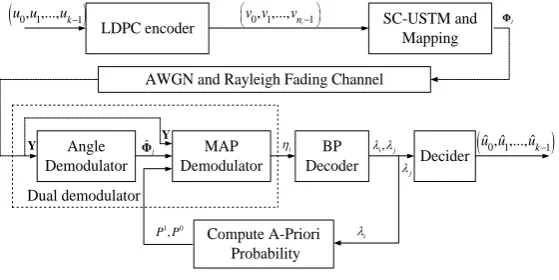
5.1. Iterative Dual-Demodulate-Decoder
In order to improve the performance,the dual-demodulator in Figure 2 can be modified into the dual-demodu- late-decoder with iterative feedback loop as shown in Figure 4. The key problem is how to design the interface from the decoder output port to the MAP demodulator input port. The BP decoder outputs nc soft values
(
0,1, , 1)
i i nc
[image:8.595.160.467.497.682.2]λ = − in parallel. On the one hand, k effective soft information values λj
(
j=0,1,,k−1)
taken from nc soft values λi(
i=0,1,,nc−1)
are fed into the decider which gives the decoded information sequence(
u uˆ0,ˆ1,,uˆk−1)
. On the other hand, nc soft values λi can be delivered to the input port of the MAP demodulator by a feedback loop. Note that λi cannot directly be fed into the MAP demodulator, because the MAP demodulator needs the input of the priori probability of the ith bit zi =zl,τ of the codeword with theFigure 3. Performance curves for the 3 and 16 points dual-demodulate-decoders of the
LDPC-coded SC-USTM system, as well as for the angle demodulator without LDPC code.
0 5 10 15 20 25 30
10-7 10-6 10-5 10-4 10-3 10-2 10-1 100
E b / N 0 ( d B )
B E R
L=16, no LDPC code
L=16, 3 points, with LDPC code
OALibJ | DOI:10.4236/oalib.1100550 9 September 2014 | Volume 1 | e550
LDPC encoder SC-USTM and Mapping
AWGN and Rayleigh Fading Channel
Angle Demodulator BP Decoder MAP Demodulator Decider
(
u u0, ,...,1 uk−1)
(
u uˆ ˆ0, ,...,1 uˆk−1)
0, ,...,1 nc1
v v v−
Y ηi
j
λ
1 0
,
P P Compute A-Priori Probability Y ˆ l Φ Dual demodulator i λ l Φ , i j λ λ
Figure 4. Noncoherent MIMO transmitter and receiver for the LDPC-coded
SC-USTM system equipped with the iterative dual-demodulator.
size nc. Therefore, in the feedback loop, the well-known priori probability P1=P z
(
i =zl,τ =1)
and(
)
0
, 0
i l
P =P z =zτ = of zi =zl,τ are computed as follows: 1 e 0 1
,
e 1 e 1
i i i P P λ λ λ = =
+ + (8)
So (7) can be modified as:
(
)
(
)
(
)
{ }(
)
(
)
{ }(
)
(
)
{ }(
)
(
)
1 1 0 0 1 1 ˆ , , ˆ , ˆ ,cos 2π sin 2π e
exp
1 e 1
log
cos 2π sin 2π 1
exp
1 e 1
cos 2π sin 2π
exp
1 log
cos 2π sin 2π
exp
1
i
i
i l l l L
i loop i l
l l l L
l l l L
l L l L
M T
z z
l L l L
M T
l L l L
M T
l L l L
M τ τ τ τ τ τ λ λ τ λ
α β γ
ρ η η
α β γ
ρ
α β γ
ρ
α β γ
∈ ⊆ ∈ ⊆ ∈ ⊆ + + + + = = = + + + + + + + = + + +
∑
∑
∑
{ }0,0 ˆ
i
l lτ τl L T
λ ρ ∈ ⊆ +
∑
(9)We call (9) the iterative dual-demodulating algorithm of the SC-USTM.
5.2. Improving Scheme of Iterative Dual-Demodulating Algorithm
We observe the values of(
0, 1, , 1)
c
n
λ λ λ − outputted from the BP decoder and find that the value range of λi
is between 0 and 1. Therefore, the boundary of decision in decider is set as 0.5, i.e., when λ >i 0.5, the decoded
bit uˆi =1; when λ <i 0.5, uˆi =0. If we modify each λi by means of translating λi into ˆλi =λi−0.5, then
we can obtain the following decision: when ˆλi =λi−0.5>0, uˆi =1; when ˆλi =λi −0.5<0, uˆi =0. The
theoretical basis of this modification is that comparison of numerical magnitudes, such as λi0.5, is changed into the detection of plus or minus, or a zero-crossing detector is more accurate and has lower complexity than a one-nonzero-threshold detector in decision device. This modification makes the priori probability values of (8) change as follows
05
1 0
0.5 0.5
e 1
,
e 1 e 1
i i i P P λ λ λ − − − = =
+ + (10)
and the iterative dual-demodulating algorithm of (9) is changed as follows
(
)
(
)
(
)
{ }(
)
(
)
{ } 1 1 0 0 ˆ , , ˆ ,cos 2π sin 2π exp
1
log 0.5
cos 2π sin 2π exp
1
l l l L
i loop i l i
l l l L
l L l L
M T
z z
l L l L
M T
τ τ
τ τ τ
α β γ
ρ
η η λ
α β γ
[image:9.595.175.455.86.226.2]OALibJ | DOI:10.4236/oalib.1100550 10 September 2014 | Volume 1 | e550
We call (11) the improved iterative dual-demodulating algorithm of the SC-USTM.
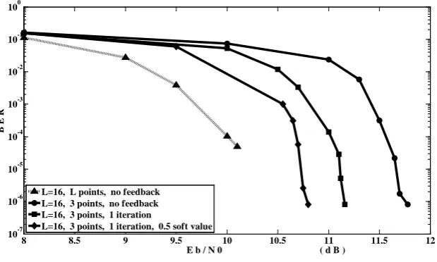
Figure 5 shows the performance comparison of four schemes. The dot line and the solid line with circle
symbol respectively denote the performance curves of the SC-USTM MAP demodulating algorithm of (3) and the simplified SC-USTM MAP demodulating algorithm with three points of (7), which is the same as Figure 3. The solid line with square symbol shows the performance curve of the dual demodulator with three points and one iterative feedback for (9), which is superior to the performance of the simplified SC-USTM MAP demodu-lating algorithm of (7) about 0.8 dB at the BER level of 1.0 10× −6.
The solid line with rhombus symbol shows the performance curve of improved iterative dual-demodulating algorithm of (11). The complexity from (9) to (11) does not almost increase, but the performance improves 0.5 dB at 10−6 BER.
Note that when the iterative time of feedback loop in Figure 4 is larger than 2, the performance improvement is unremarkable but the computational complexity of the demodulator increases by multiples, the reason will be discussed late on.
6. Complexity Analysis
In this section, we roughly assess the computational complexity of several demodulating schemes of the differ-ent noncoherdiffer-ent space time receivers by comparing the presdiffer-ented LDPC coded SC-USTM noncoherdiffer-ent demo-dulator with the existing turbo coded noncoherent space-time demodemo-dulator based on information-bearing pilots and spatial multiplexing in [7]. We first give the computational complexities of several demodulating algorithms, and then compare them with the complexity of the existing noncoherent space time demodulators.
The total calculated amount of (3) is one complex logarithm, L complex exponents,
(
6MN+ ×4)
L real additions,(
6MN+ ×5)
L real multiplications and(
MN+2)
L trigonometric calculations.The total calculated amount of (2) is one complex logarithm, L complex exponents, MNTL
(
3T−5 2)
real additions and MNTL(
4T−1)
real multiplications and MNTL T(
−1 2)
trigonometric calculations.The well-known coherent MAP demodulating algorithm of (10) in [19] needs one complex logarithm, L
complex exponents,
(
4N+2)
ML real additions and(
4N+4)
ML real multiplications.For example, let T=2M=2N=4 and L=16, except the same part of complex logarithm and exponents, for the rest part containing real addition and multiplication, the complexity of the SC-USTM MAP demodulat-ing algorithm usdemodulat-ing (3) is small 4.5 times on average, compared to the complexity of the general MAP demodu-lating algorithm using (2), and is about 1.3 times larger than the complexity of the coherent MAP demodudemodu-lating algorithm in [19].
Except for the same calculation of one logarithm and L exponents, the difference of the calculated amount between (2) and (3) is mainly resulted from tr
(
Y∗Φ Φl l∗Y)
. In (2), the transmit signal matrix Φl taking partingFigure 5. Performance curves for four dual-demodulators, 3 and 16 points, one
itera-tion and modifying parameter λi.
8 8.5 9 9.5 10 10.5 11 11.5 12
10-7 10-6 10-5 10-4 10-3 10-2 10-1 100
E b / N 0 ( d B )
B E R
L=16, L points, no feedback L=16, 3 points, no feedback L=16, 3 points, 1 iteration
[image:10.595.160.470.503.689.2]OALibJ | DOI:10.4236/oalib.1100550 11 September 2014 | Volume 1 | e550
in the calculation of tr
(
Y∗Φ Φl l∗Y)
is a complex matrix in which all elements are the modulation symbol of M- QAM or M-PSK, but in (3), Φl is a sparse real matrix consisted of zero elements and real elements of trigo- nometric function which results in the simplified calculation of tr(
Y∗Φ Φl l∗Y)
. The difference of the calculated amount between (3) in this paper and (10) in [19] is that the noncoherent USTM demodulation, for example (3), is performed by considering all signal matrix Φl, but the coherent demodulation, for example (10) in [19], by only modulation symbol-wise.As the calculated amount of the angle demodulating algorithm of (6) is 4MN + 2 real additions and 4MN + 4 real multiplications plus one arc tangent, so the total calculated amount of the simplified SC-USTM MAP de-modulating algorithm with ˆL points of (7) is one complex logarithm, ˆL complex exponents,
(
)
ˆ 3 5 2
MNTL T− real additions and MNTLˆ 4
(
T−1)
real multiplications and MNTL Tˆ(
−1 2)
trigonometric calculations for ˆL=3, 5, 7.In order to determine the total calculated amount of the simplified MAP demodulating algorithm of (10) in [7]
based on the orthogonal USTM presented in [12], we need to know the calculated amount of tr
(
Y∗Φ Φl l∗Y)
. It is MNT(
3T−5 2)
real additions, MNT(
4T−1)
real multiplications and MNT T(
−1 2)
trigonometric calculations. So (10) in [7] needs about twice calculated amount of tr(
Y∗Φ Φl l∗Y)
and its complexity is about(
2)
2
O MNT . The complexity of the above two demodulating algorithms is independent on the size of constella-tion L, and they exploit the special structural feature of the transmit signal matrix to achieve the goal of reduc-ing the calculated amount of demodulatreduc-ing algorithm. Obviously, the calculated amount of the angle demodu-lating algorithm of (6) is less at least T times than that of the simplified MAP demodulating algorithm of (10) in [7].
We design three LDPC coded SC-USTM noncoherent MIMO receivers without estimating the CSI which completely differ from the existing coded space-time noncoherent receivers in [7]. If the LDPC codes as outer code in these three receivers have the same construction and their decoders use the same BP decoding algorithm with 20 iterations, which means to have the same decoding complexity, then the main difference of three receiv-ers rests with the distinct demodulators. Therefore, we need only to analyze the complexity of the whole demo-dulating scheme of these receivers to the exclusion of LDPC decoder. The first receiver is equipped by the SC-USTM MAP demodulator of (2) whose complexity is the total calculated amount of (3), i.e., O
(
6MNL)
, see the Subsection B of the Section III. The second receiver is mounted by the dual-demodulator, consisting of the angle demodulator and the simplified SC-USTM MAP demodulator with three points, whose complexity is the sum of the total calculated amount of (6) and (7), i.e. O MNT L(
2ˆ)
. When M, N are given and T =2M(the structural constraint of SC-USTM satisfying cos2x+sin2x=1) is fixed, then the second receiver has low-er complexity than the first receivlow-er as the size of constellation L increases. The third receiver consists of one
iterative feedback dual-demodulator/decoder whose complexity is twice sum of the total calculated amount of (6) and (7) as well as repeat iterations of decoder. When L is very large, the complexity of the third receiver is lower than that of the first receiver.
A Turbo coded noncoherent space-time modulation using information-bearing pilots and spatial multiplexing (SM) is presented in [7], and in its receiver, called as iterative detection and decoding (IDD) receiver, demodu-lating scheme consists of two parts. The first part consists of a simplified noncoherent MAP demodudemodu-lating algo-rithm of (10) in [7] and the second part has a more complex structure which consists of three modules such as channel estimator, coherent demodulator and signal matrix detector. The calculated amount of channel estimator
is determined by a preliminary LMMSE channel estimate
1 ˆ
M l l l
M M
ρ ρ
−
∗ ∗
= +
H I Φ Φ ΦY which contains
matrix inversion and multiplication of three matrices which is not less than the calculated amount of multiplica-tion of four matrices. The calculated amount of signal matrix detector is determined by (11) in [7] which in-volves in matrix inversion and multiplication of five matrices, as well as traversal calculation of 2δ candidate points. Obviously, the calculated amount of channel estimator is larger than that of (7). Thus it can be concluded that the complexity of the second and third receiver is lower than the IDD receiver in [7].
OALibJ | DOI:10.4236/oalib.1100550 12 September 2014 | Volume 1 | e550
improve performance. The SC-USTM has such structural feature that the matrix elements contains zero ele-ments as many as possible and special type similar to standard function, such as trigonometric function, which is the determining factor of resulting in the simplified demodulating algorithm.
7. Conclusion and Natural Works
We have designed three low complexity receivers for the LDPC-coded USTM noncoherent MIMO system which need not send the pilot information at the transmitter and estimate the channel state information at the re-ceiver. The computational complexity of the second and third receivers is independent on the size of constella-tion and the coherent interval. Therefore, they are lower than that of the existing noncoherent space-time receiv-ers.
Funding
This work is supported by National Natural Science Foundation of China under Grant No. 61071069.
References
[1] Telatar, E. (1999) Capacity of Multi-Antenna Gaussian Channels. European Transactions on Telecommunications, 10, 585-595. http://dx.doi.org/10.1002/ett.4460100604
[2] Foschini, G.J. (1996) Layered Space-Time Architecture for Wireless Communication in a Fading Environment When Using Multi-Element Antennas. Bell System Technical Journal, 1, 41-59. http://dx.doi.org/10.1002/bltj.2015
[3] Marzetta, T.L. and Hochwald, B. (1999) Capacity of a Mobile Multiple-Antenna Communication Link in Ray-leigh-Flat Fading. IEEE Transactions on Information Theory, 45, 139-157. http://dx.doi.org/10.1109/18.746779
[4] Hochwald, B.M. and Marzetta, T.L. (2000) Unitary Space-Time Modulation for Multiple-Antenna Communications in Rayleigh Flat Fading.IEEE Transactions on Information Theory, 46, 543-564. http://dx.doi.org/10.1109/18.825818
[5] Zheng, L. and Tse, D.N.C. (2002) Communication on the Grassmann Manifold: A Geometric Approach to the Nonco-herent Multiple-Antenna Channel. IEEE Transactions on Information Theory, 48, 359-383.
http://dx.doi.org/10.1109/18.978730
[6] Krishnamoorthy, A. and Anastasopoulos, A. (2005) Code and Receiver Design for the Noncoherent Fast-Fading Channel. IEEE Journal on Selected Areas in Communications, 23, 1769-1778.
http://dx.doi.org/10.1109/JSAC.2005.853802
[7] Chen Y. and Ueng, Y. (2011) Turbo Coded Noncoherent Space-Time Modulation Using Information-Bearing Pilots and Spatial Multiplexing.IEEE Transactions on Communications, 59, 1543-1559.
http://dx.doi.org/10.1109/TCOMM.2011.042111.100169
[8] Hassibi, B. and Hochwald, B.M. (2003) How Much Training Is Needed in Multiple-Antenna Wireless Links? IEEE
Transactions on Information Theory, 49, 951-963. http://dx.doi.org/10.1109/TIT.2003.809594
[9] Yu, Y., Giannakis, G.B. and Jindal, N. (2007) Information-Bearing Noncoherently Modulated Pilots for MIMO Train-ing. IEEE Transactions on Information Theory, 53, 1160-1168. http://dx.doi.org/10.1109/TIT.2006.890693
[10] Hochwald, B.M., Marzetta, T.L., Richardson, T.J., Sweldens, W. and Urbanke, R. (2000) Systematic Design of Unitary Space-Time Constellations. IEEE Transactions on Information Theory, 46, 1962-1973.
http://dx.doi.org/10.1109/18.868472
[11] Tarokh, V. and Kim, I.M. (2002) Existence and Construction of Noncoherent Unitary Space-Time Codes. IEEE Tran-
sactions on Information Theory, 48, 3112-3117. http://dx.doi.org/10.1109/TIT.2002.805075
[12] Zhao, W., Leus, G. and Gannakis, G.B. (2004) Orthogonal Design of Unitary Constellations for Uncoded and Trel-lis-Coded Noncoherent Space-Time Systems. IEEE Transactions on Information Theory, 50, 1319-1327.
http://dx.doi.org/10.1109/TIT.2004.828154
[13] Gohary, R.H. and Davidson, T.N. (2009) Noncoherent MIMO Communication: Grassmannian Constellations and Effi-cient Detection. IEEE Transactions on Information Theory, 55, 1176-1205.
http://dx.doi.org/10.1109/TIT.2008.2011512
[14] Bahceci, I. and Duman, T.M. (2002) Combined Turbo Coding and Unitary Space-Time Modulation. IEEE
Transac-tions on CommunicaTransac-tions, 50, 1244-1249. http://dx.doi.org/10.1109/TCOMM.2002.801484
[15] Wei, R., Hsu, Y. and Pan, C. (2009) A Low-Complexity Noncoherent Iterative Space-Time Demodulator. IEEE Trans-
actions on Communications, 57, 2895-2898. http://dx.doi.org/10.1109/TCOMM.2009.10.080056
OALibJ | DOI:10.4236/oalib.1100550 13 September 2014 | Volume 1 | e550
IEEE Transactions on Wireless Communications, 3, 2335-2344.
[17] Tran, N.H., Nguyen, H.H. and Tho, L.N. (2007) Coded Unitary Space-Time Modulation with Iterative Decoding: Error Performance and Mapping Design. IEEE Transactions on Communications, 55, 703-716.
[18] Vu, H.G., Nguyen, H.H. and Dodds, D.E. (2008) Performance Bound for LDPC Coded Unitary Space-Time Modula-tion. Wireless Personal Communications, 47, 383-397. http://dx.doi.org/10.1007/s11277-008-9487-0
[19] Stefanov, A. and Duman, T.M. (2001) Turbo-Coded Modulation for Systems with Transmit and Receive Antenna Di-versity over Block Fading Channels: System Model, Decoding Approaches, and Practical Considerations. IEEE
Jour-nal on Selected Areas in Communications, 19, 958-968. http://dx.doi.org/10.1109/49.924879
[20] Peng, L., Yang, L. and Peng, Q. (2011) A Low-Complexity IRA-LDPC Coded Noncoherent Unitary Space-Time Mo- dulation System on Rayleigh Flat Fading Channel. 2011 2nd International Conference on Mechanic Automation and
Control Engineering, Hohhot, 15-17 July 2011, 7115-7118.