New Techniques for Daubechies Wavelets and
Multiwavelets Implementation using Quantum
Computing
Saleem M. R. Taha,
Ph.DDepartment of Electrical Engineering College of Engineering, University of Baghdad
Jadiryah, Baghdad, Iraq
Walid A. Mahmood,
Ph.DDepartment of Electrical Engineering College of Engineering, University of Baghdad
Jadiryah, Baghdad, Iraq
ABSTRACT
In this paper, new techniques to implement the Daubechies wavelets and multiwavelets are presented using quantum computing synthesis structures. Also, a new quantum implementation of inverse Daubechies multiwavelet transform is proposed. The permutation matrices, particular unitary matrices, play a pivotal role. The particular set of permutation matrices arising in quantum wavelet and multiwavelet transforms is considered, and efficient quantum circuits that implement them are developed. This allows the design of efficient and complete quantum circuits for the quantum wavelet and multiwavelet transforms.
General Terms
Design, Theory, Algorithms
Keywords
Quantum Circuits, Quantum Computing, Wavelet Transforms, Multiwavelet Transforms
1.
INTRODUCTION
As it happens in classical signal analysis, it is natural to expect that quantum wavelet transform will find important future applications [1] for the treatment of quantum databases and quantum data compression. Therefore, it is important to develop quantum circuits for implementing wavelet and multiwavelet transforms. Wavelets have been around since the late 1980s, and have found many applications in signal processing, numerical analysis, operator theory, and other fields [2]. The wavelet transform is a tool that cuts up data or functions or operators into different frequency components, and then studies each component with a resolution matched to its scale. The wavelet transform of a signal evolving in time depends on two variables: scale (or frequency) and time; wavelets provide a tool for time-frequency localization [3]. One generalization is multiwavelets, which have been around since the early 1990s. Multiwavelets have some advantages: they can have short support coupled with high smoothness and high approximation order, and they can be both symmetric and orthogonal. They also have some disadvantages: the discrete multiwavelet transform requires preprocessing and post processing steps. Also, the theory becomes more complicated [2].
In this paper, efficient and complete quantum circuits are derived for the quantum Daubechies D(4) wavelet and
Fortunately, there is an important class of computations, the unitary transforms, such as the Fourier transform, Walsh-Hadamard transform and wavelet transforms, that are describable in terms of unitary operators [4]. The Fourier and Walsh-Hadamard transforms have been used most extensively by the quantum computing algorithms [5] – [11]. However, the wavelet transforms are every bit as useful as the Fourier transform; therefore it is considered, here, how to achieve a quantum wavelet transform.
The process of finding a quantum circuit that implements the unitary operator of the wavelet transform is to factor the wavelet operator into the direct sum, direct product and dot product of smaller unitary operators. These operators correspond to 1-qubit and 2-qubit quantum gates. The permutation matrices play a pivotal role in the factorization of the unitary operators that arise in the wavelet transforms. The main issue in deriving feasible and efficient quantum circuits for the quantum wavelet transforms considered in this paper, is the design of efficient quantum circuits for certain permutation matrices. The permutation matrices, due to their specific structure, represent a very special subclass of unitary matrices [4]. Therefore, the exploitation of this specific structure represents the key to achieve an efficient quantum implementation of permutation matrices. In this paper, two representative wavelet kernels are considered, the Daubechies D(4) wavelets and multiwavelets. Two new decompositions which lead to gate-level circuits for their implementations are developed.
The rest of the article is organized as follows. Two fundamental quantum wavelet pyramidal and packet algorithms are introduced in Section 2, as well as quantum circuits for the perfect shuffle permutation matrices which arise in quantum wavelet transforms are discussed in this section, too. New quantum implementations of the most popular discrete wavelet transform, namely, the 4-coefficient Daubechies wavelet and multiwavelet transforms are developed in Section 3 and Section 4, respectively. While Section 5 deals with quantum implementation of the inverse Daubechies multiwavelet transform. Finally, the conclusion section summarizes this work.
2.
WAVELET PYRAMIDAL AND
PACKET ALGORITHMS
8 quantum counterparts of these algorithms is the development
of suitable factorizations. Consider the Daubechies fourth-order wavelet kernel of dimension 2i , denoted as . The factorizations of PAA and PYA for a 2n –dimensional vector are given as [4]
(2)
These factorizations allow analysis of the feasibility and efficiency of quantum implementations of the packet and pyramid algorithms.
A set of efficient and practically realizable circuits for implementation of Qubit Permutation Matrices can be built by using the qubit swap gate, , where
=
.
The gate, shown in Figure 1a, can be implemented with three EXOR (or Controlled-NOT) gates as shown in Figure 1b.
(a) (b)
Fig 1: The gate (a) and its implementation by using three EXOR (Controlled-NOT) gates (b).
A circuit for implementation of by using gates is shown in Figure 2. This circuit is based on a simple idea of successive swapping of the neighboring qubits.
[image:2.595.311.543.74.427.2]
Fig 2: Implementation of perfect shuffle permutation matrix, .
The most popular discrete wavelet transform, namely, the Daubechies fourth-order wavelet kernel of dimension 2n is given in a matrix form as [4]
(3)
Where c0 = , c1 = , c2 = , and c3 = .
A factorization of is proposed in [4] as
= (I2n-1 C1) Q2n (I2n-1 C0` ) (4)
Where C0` = 2 and Q2 n
is the downshift permutation matrix given by
Q2 n
=
[image:2.595.54.252.386.431.2]
(5)
Figure 3 shows a block-level implementation of Equation (4). Clearly, the main issue for a practical quantum gate-level implementation of Equation (4) is the quantum implementation of matrix Q2n .
Fig 3: A block-level circuit for implementation of [4].
3.
QUANTUM IMPLEMENTATION OF
DAUBECHIES
D
(4)WAVELET
TRANSFORM
A new circuit for implementation of permutation matrix Q2 n
is developed based on its description as a quantum arithmetic operator. Such a quantum arithmetic description of Q2
n is given as:
Q2n: → (6) Where (7)
Q
2n [image:2.595.55.271.505.618.2]This description of Q2nallows its quantum implementation and hence by using quantum arithmetic circuits with a complexity of O(n). Whereas, in classical solutions there are known algebraic techniques for factoring an arbitrary
operator, they are guaranteed to produce O( ) [4], i.e., exponentially many, terms in the factorization. Hence, although such a factorization is mathematically valid, it is physically unrealizable, because when treated as a quantum circuit design, would require too many quantum gates. It is therefore clear that for achieving an efficient quantum implementation, i.e., with a polynomial time and space complexity, it is necessary to exploit the specific structure of the given unitary operator.
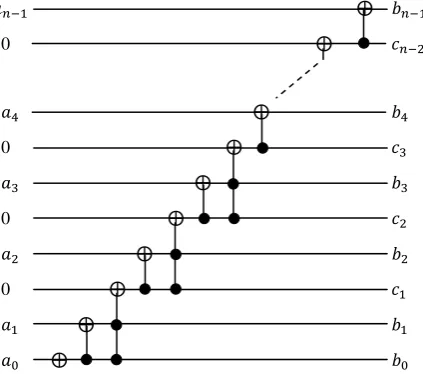
In the following, it is shown how a circuit for
1 2 can be constructed. In binary representation, this mapping can be specified in terms of the following operations:
→ , with b0 = a0 1
b1 = a1 a0 1 = a1 b0
b2 = a2 c1where c1 = b0 b1 ,
b3 = a3 c2where c2 = b2 c1 ,
bi = ai ci-1 where ci-1 = bi-1 ci-2 .
Calculating the ci’s and then the bi’s, the circuit in Figure 4 is obtained. Replacing the block Q2
n
in Figure 3 with the circuit in Figure 4, then Figure 3 represents a complete gate-level circuit for implementation of .
0
[image:3.595.58.270.439.626.2]
0 0 0
Fig 4: A new circuit for implementation of permutation matrix Q2n.
4.
QUANTUM IMPLEMENTATION OF
DAUBECHIES
D
(4)MULTIWAVELET
TRANSFORM
Classical wavelet theory is based on a scaling function ϕ(t) and a wavelet function ψ(t),multiwavelets have two or more scaling and wavelet functions. The scaling function ϕ(t) is replaced by a function Φ(t) = [ϕ1(t) . . . ϕr(t)]T called a
defined from the set of wavelet functions as Ψ(t) = [ψ1(t) . . . ψr(t)]T .
The multiwavelet two-scale equations:
Φ(t) = k Φ(2t – k) (8)
Ψ(t) = k Φ(2t – k) (9)
The recursion coefficients Hk and Gk are the low and high-pass filter impulse responses. They are r r matrices for each integer k. In practice, the value of r equals 2. The Hk and Gk scaling and wavelet matrices for GHM filter are [2]
H0=
, H1=
, H2=
H3=
(10)
G0=
G1=
G2=
G3=
(11)
For computing discrete multiwavelet transform (DMWT), the transform matrix (T) can be written as in Equation (12). The input signal is preprocessed by repeating the input stream with the same stream multiplied by a constant , for GHM system functions
.
A new quantum implementation of Daubechies D(4) multiwavelet is proposed here, as follows.
T = (12)
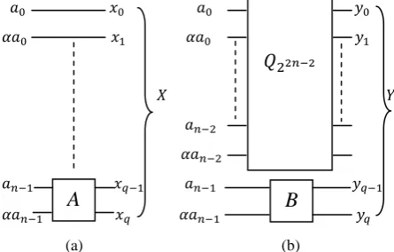
The transformation matrix T (Equation 12) can be decomposed as the summation of two matrices X and Y. The matrix X is shown below:
X = (13)
The matrix X is a , where n is the number of input bits; it can be described as:
A (14) Where, A = (15)
The , , , and are as given in Equations (10) and (11), respectively.
10 Y=
(16)
The matrix Y can be described as:
Y = (17) Where, B = (18)
is the downshift permutation matrix as described in the previous Section. The H2 , H3 , G2 , and G3are as given in Equations (10) and (11), respectively. Figure 5 shows the quantum realizations of the matrices X and Y as specified by Equations (14) and (17), respectively. The circuit of the block
in Figure 5b is as shown previously in Figure 4.
[image:4.595.52.274.70.201.2]
(a) (b)
Fig 5: The realization of: (a) Equation 14, (b) Equation 17; where q = 2n – 1.
Now, to obtain a single level of the D(4) multiwavelet transform, the X and Y outputs of Figure 5a&b are applied as inputs to a quantum adder circuit as shown in Figure 6.
Fig 6: The realization of the Daubechies D(4) multiwavelet transform.
The addition of two registers and can be written as
, where the result of addition is written into one of the input registers. To prevent overflows, the second register (initially loaded in state ) should be of size q + 1 if both X and Y are encoded on q qubits. In addition, a temporary register of size q is required, initially in state , to which the carries of the addition are written (the last carry is the most significant bit of the result and is written in the last qubit of the second register) [12].
5.
QUANTUM IMPLEMENTATION OF
INVERSE DAUBECHIES
D
(4)MULTIWAVELET TRANSFORM
A new quantum implementation of inverse Daubechies D(4) multiwavelet transform is proposed here, as follows.
The reconstruction matrix R, Equation (19), which is the transformation matrix T transposed, can be decomposed as the summation of two matrices Z and W.
R = (19)
The matrix Z is shown below:
Z = (20)
The matrix Z can be described as:
C (21) Where, C = (22)
The H0 , H1 , G0 , and G1 are as given in Equations (10) and (11), respectively. The matrix W is:
W =
(23)
The matrix W can be described as:
W D (24) Where,
(25)
and D = . (26)
The H2 , H3 , G2, and G3 are as given in Equations (10) and (11), respectively. The realization of Equation (21) is similar to that of Equation (14). Also, the realization of Equation (24) is similar to that of Equation (17), but the (i.e. the
transpose of the downshift permutation matrix) is used instead
A
B
Quantum
[image:4.595.53.276.279.421.2]of . Figure 7 shows the entire quantum implementation of the inverse D(4) multiwavelet transform.
The quantum arithmetic description of is given as: : Where (mod ).
This description of allows its quantum implementation. Hence, it is required to construct a quantum circuit for
. In binary representation, this
mapping can be specified in terms of the following operations:
[image:5.595.52.274.218.349.2]
Fig 7: Implementation of the inverse Daubechies D(4)
multiwavelet transform.
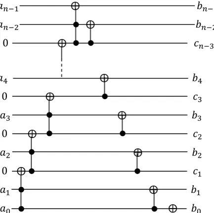
, with
b0 = a0 1 b1 = a1 a0
b2 = a2 c1 , where c1 = a1 a0
bi = ai ci – 1 , where ci – 1 = ai – 1 ci – 2 for 3 n - 1 Calculating the ci’s and then the bi’s, the circuit in Figure 8 is obtained.
Fig 8: A new circuit for implementation of permutation matrix.
6.
CONCLUSIONS
In this paper, fast algorithms for quantum Daubechies D(4) wavelet, multiwavelet and inverse multiwavelet transforms are developed. Three complete circuits for these three types of Daubechies D(4) transforms are described. Permutation matrices , , and play a pivotal role in the development of the three types of transform. In fact, not only they arise explicitly in the packet and pyramid algorithms but also they play a key role in factorization of wavelet kernels and in decomposition of multiwavelet and inverse multiwavelet transforms.
In this paper, the Daubechies quantum wavelet and multiwavelet transforms are implemented. In a similar manner, the other types of wavelet and multiwavelet transformations can be achieved (a promising task for the future).
7.
REFERENCES
[1] Terraneo, M., and Shepelyansky, D. L. 2003. Imperfection effects for multiple applications of the quantum wavelet transform. Physical Review Letters, 90 (25), 257902-(1-4).
[2] Keinert, F. 2004. Wavelets and multiwavelets. Chapman & Hall/CRC.
[3] Daubechies, I. 1992. Ten lectures on wavelets. SIAM, Philadelphia.
[4] Fijany, A. and Williams, C. P. 1998. Quantum wavelet transforms: fast algorithms and complete circuits. 1st NASA International Conference on Quantum Computing and Communication, Palm Spring, CA, (Feb. 17-21, 1998). Available: www.arXiv:quant-ph/9809004v1,1998. [5] Imre, S., and Balazs. F. 2005. Quantum computing and communications: an engineering approach. John Wiley & Sons Ltd.
[6] Kaye, P., Laflamme, R., and Mosca, M. 2007. An introduction to quantum computing. Oxford University Press Inc.
[7] Nielsen, M. A., and Chuang, I. L. 2000. Quantum computation and quantum information. Cambridge University Press, Cambridge, UK.
[8] Jozsa, R, 1997. Quantum algorithms and the Fourier transform. Los Alamos preprint archive. Available: http://xxx.Lanl.Gov/archive/quant-ph/9707033,1997. [9] Barenco, A., Ekert, A., Suominen, K-A, and Torma, P.
1996. Approximate quantum Fourier transform and decoherence. Physical Review A, 54 (139), (Jan. 21, 1996). Available: www.arXiv:quant-ph/9601018v1,1996. [10]Høyer, P. 1997. Efficient quantum transforms. (Feb. 12, 1997). Available: http://xxx.lanl.gov/archive/quant-ph/9702028,1997.
[11]Klappenecker, A. 1999. Wavelets and wavelet packets on quantum computers. (Sep. 3, 1999). Available: http://xxx.Lanl.gov/archive/quant-ph/9909014v1,1999. [12]Vedral, V., Barenco, A., and Ekert, A. 1995. Quantum
network for elementary arithmetic operations. Physical Review A, 54 (147). Available: www.arXiv.org/quant-ph/9511018v1,1995.
C
![Fig 3: A block-level circuit for implementation of [4].](https://thumb-us.123doks.com/thumbv2/123dok_us/8066674.778096/2.595.54.252.386.431/fig-block-level-circuit-implementation.webp)