Eigen Value Analysis of Optimal Controller Design of
Wheeled Autonomous Mobile Robot
Shahida Khatoon
D/o Electrical Engineering F/o Engineering & Technology
Jamia Millia Islamia New Delhi-110025
India
Kaukab Naz,
D/o Electrical Enggineering F/o Engineering & Technology
Jamia Millia Islamia New Delhi-110025
India
Ibraheem
D/o Electrical Enggineering F/o Engineering & Technology.
Jamia Millia Islamia .New Delhi-110025
India
ABSTRACT
The autonomous wheeled mobile robots (AWMR) are subjected to high demands concerning stability, controllability and safety. Therefore, it becomes very important to devise the effective and efficient control strategies for such system to get desired system dynamic performance. In this paper the state space model of the system has been developed, the dynamic behavior of the system has been studied and then optimal controllers are designed using full state feedback control strategy. The optimal controllers are designed for various operating conditions using pole placement technique. The dynamic response plots are obtained for various system states considering various operating conditions. The investigations of these reveal that the implementation of optimal controllers offer not only good dynamic performance, also ensure system dynamic stability.
Keywords
Autonomous wheeled mobile robot (AWMR), Linear quadratic regulator (LQR), Error weighting matrix Q, Control weighting matrix R,
1.
INTRODUCTION
Recently mobile robot has been one of the central subjects in the research and development arena in the field of autonomous agents. They have been extensively applied in service industry, surveillance, geographical survey, remote access of dangerous location around the world as well as in domestic needs some of the many aspects which are typically studied in mobile robotics are path planning, trajectory tracking and controller stabilization. Non-holonomic robot is a popular differential drive mobile robot which is used in research as well as industrial applications [12]. However, few problems are associated with this type of robot is its high speed motion and hence the difficulty in avoiding actuator velocity saturation[13]. This difficulty is overcome by modifying the trajectory tracking error appropriately[16,17]. According to the design criteria, the control law is defined such as to reduce the difference between future trajectory tracking error of the robot and the reference one. The other area of interest for researchers is to achieve the shortest path length of robot trajectory. In [11], a randomized planner is applied to surveillance robot to get optimal path. A differential drive mobile robot is applied to the area of defense and security patrolling [12,13] in which sensor signals are mapped into actuator response using behavioral architecture. This regulates both translational and rotational movements of the robot. A discussion of different steering controls where PWM is applied to control DC motor for stable navigation strategy is presented in[14].
The aim of this research is to investigate the suitability and examine the performance of linear control systems like the Linear Quadratic Regulator and Pole-placement controller in stabilizing the robotic system. The dynamic behavior of the robot needs to be described by a mathematical model in order to arrive at an efficient control strategy for the balancing of robot. In this work the equation of motion for a wheeled mobile robot and linear model for a DC motor is derived in detail. The robot is actually powered by two DC motors. First of all the state space model of the DC motor is derived. Then this model is used todrivethe dynamic model of the robot that provides a relationship between the input voltages to the actuators, in this case motors,and the control torque needed to control the mobile agent.
2.
LITERATURE SURVEY
developed to carry out the study by simulation of the system aswell as the surrounding conditions [5].There have been research and in the field of mapping of dynamic environment of the robotic system so that it can navigate in free space with minimum human intervention [4,13,15,16]. So it is not only the best experimental tool but also an ideal experimental platform. The research of inverted pendulum has profound meaning in theory and methodology, and has valued by various countries’ scientists and different strategies to control the movement either limited or free [17,18].The constraints of the inverted pendulum robot are same as the constraint of two wheeled mobile robot, which produced the model error and it effects to the position and orientation errorsA MOEA based LQR weighting matrices design approach is proposedin [21]. The multi-objective optimization model of LQR weighting matrices is established[19].Then optimal control for trajectory tracking and stability of the system using LQR and PID controllers is described in [20]. The dynamical model of a TWIP mobile robot can be derived using various methods but most popular is Euler Lagrange approach[20-21],modified Lagrange multiplier method [22]. Comparisons between model based and non-model base controllers and also conventional PID controller for a balancing the robot is a common research interest and has been presented by various researchers. Fuzzy Logic Controllers are non-model based performs better than the LQR and PID controllers in terms faster response and less overshoot, but has higher energy consumption than the other two[2,7,23]. A detailed description for derivation of dynamic mathematical model is discussed and employed in [24].
3.
MATHEMATICAL MODEL OF
AWMR SYSTEM
The mathematical model of the autonomous wheeled mobile robot (AWMR) system has been derived by Lagrange’s method [24]. The main objective is to balance the AWMR system by applying the required control force.In this study the two dimensional model of the AWMR system is modeled. For this system we considered input as the control force needed to keep the AWMR stable in a vertical position and the outputs are tilt angle ‘⍺’ and the cart position .we linearized the equation of motions about vertical axis,i.e. tilt angle ⍺= π.
Also this is assumed that the system remains stable and deviate negligibly by some angle ϓ.Thus ⍺ = (π +ϓ)
The equations governing the system are as follows: ( +
( + +
State vector is defined as [
⍺
⍺
]TWhere = Cart Position (m),
= Cart Velocity (m/s)
⍺ = Pendulum Angle from the vertical (rad),
= Angular Velocity of pendulum (rad/sec)
Control input vector U = [u1] T
The transfer function of the AWMR system is obtained as follows;
T s u ( (
(
rad/N
T s u ( (
(
( ( m/N
The state space model of the system is written as
+
Y = CX + D u
Substituting the numerical values of the data from appendix A we get the values of A, B, C, and D matrices as follows;
System Matrix A =
.
. . . . .
,
Control Matrix B = .
.
,
Output Matrix C =
and Disturbance Matrix D =
The transfer function for pendulum angle (rad) ⍺ and cart position x (m) as:
(
s
+ . . .
(
. s .
+ . . .
Open loop eigenvalues = [0 -0.0111 -13 .2961 13.2806]
The unstable nature of the AWMR system described by Transfer Function1 and Transfer Function2, is evident from the
eigenvalues of the open loop system, this calls for the design of an appropriate controller.
4.
OPTIMAL CONTROLLER DESIGN
USING LINEAR QUADRATIC
REGULATOR
To design an optimal regulator, the dynamic system model is developed in state variable form. The regulator design of higher order non- linear system model, results in complex computations. Hence the linearization of the system equations about an operating point was proposed, and then the linear state- regulator theory is applied to obtain the desired control law. However this may result in higher cost complexity problems. The regulator designed with reduced number of state variables may not be optimal in realistic situations [10]. A linear time invariant power system in state space is represented by the following differential equations;
X(t) = Ax(t) + Bu(t) + Td(t)
y(t) = C x(t)
The control law is given by u = - k x
u = - k y
for full state vector feedback problem one has to minimize the performance index given by
( +
5.
SUBOPTIMAL CONTROLLER
DESIGN USING OUTPUT FEEDBACK
CONTROL STRATEGY
An optimal solution may not be the best solution in all circumstances, if all the states x(t) are not accessible for feedback, one has to go for a state observer whose complexity is comparable to that of the system itself. Hence a procedure is required that relies on the use of feedback from only the accessible state variables constraining the gain elements of matrix k corresponding to the inaccessible state variables to have zero value. It is a method of obtaining the solution of a control problem when some elements of the feedback gain matrix k are constrained. Also the damping can be provided by using an output feedback and strip eigen value assignment technique. The eigenvalues location affects the dynamics of the system. Therefore it is necessary to locate the eigenvalues at some desired positions. The exact location of all eigenvalues at each operating point is difficult to attain. But a satisfactory response for both transient and steady state can be obtained by placing all eigen values within a suitable region in complex s – plane [11-13].
The system considered here may be represented by
X= Ax + Bu; x(0) = x0
The performance index is
( +
With the linear feedback law or optimal control law for a linear combination of the state variable can be given as; u(t) = -k x(t)
The closed loop system is described by
X(t) = (A - Bk) x(t)
Substituting for control vector u in performance index, the performance index(J) will be as;
( ( +
6.
EFFECT OF CHANGING
WEIGHTING MATRICES ON THE
EIGENVALUES OF AWMR SYSTEM
The linear quadratic controller problem poses a challenge to design appropriate values of the two weighting matrices Q and R as discussed in [21]. The Q matrix specifies the relative importance to be given to the system error, which is defined as deviation from the reference value, the other matrix R describes the weightage to be given to the control vector u. As an appropriate combination of these two matrices give the complete balance of the system therefore the choices of Q and R become a criterion of utmost important while designing the linear quadratic controller for dynamic stability of the system. To analyze the effect of changing the weighting matrices on the dynamic system performance based on the eigenvalue
analysis of the AWMR system, present approach has been classified into four case studies as follows;
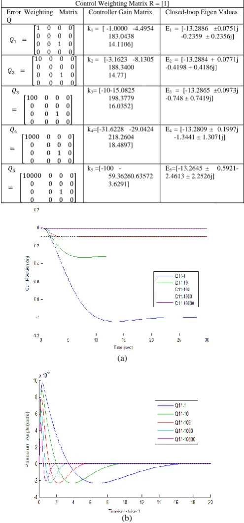
[image:3.595.309.557.174.706.2]Case Study – I: Initially the error weighting matrix Q is changed keeping control weighting matrix constant. Initially the weight of the cart position is changed and that for pendulum angle is kept unity.
Table 1: Effect of Varying Error Weighting Matrix Q on the Dynamic Performance of the System
Control Weighting Matrix R = [1] Error Weighting Matrix
Q
Controller Gain Matrix Closed-loop Eigen Values
k1 = [ -1.0000 -4.4954
183.0438 14.1106]
E1 = [-13.2886 ±0.0751j
-0.2359 ± 0.2356j]
k2 = [-3.1623 -8.1305
188.3400 14.77]
E2 = [-13.2884 + 0.0771j
-0.4198 + 0.4186j]
k3= [-10-15.0825
198.3779 16.0352]
E3 = [-13.2865 ±0.0973j
-0.748 ± 0.7419j]
k4=[-31.6228 -29.0424
218.2604 18.4897]
E4 = [-13.2809 ± 0.1997j
-1.3441 ± 1.3071j]
k5 =[100
-59.36260.63572 3.6291]
E5=[-13.2645 ±
0.5921-2.4613 ± 2.2526j]
(a)
(b)
Figure 1(a and b): Effect of Varying Error Weighting Matrix Q on the Dynamic Performance of the system
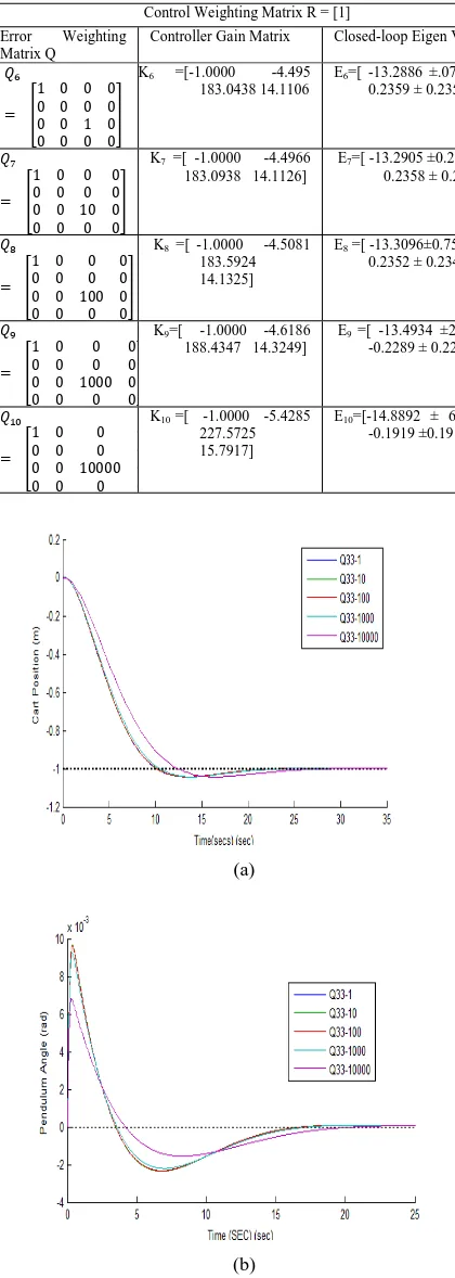
and that of pendulum angle is varied and the observations are presented in Table.2
Table.2: Effect of Varying Error Weighting Matrix Q on the Dynamic Performance of the System
Control Weighting Matrix R = [1] Error Weighting
Matrix Q
Controller Gain Matrix Closed-loop Eigen Values
K6 =[-1.0000 -4.495
183.0438 14.1106
E6=[ 13.2886 ±.0751j
-0.2359 ± 0.2356j]
K7 =[ -1.0000 -4.4966
183.0938 14.1126]
E7=[ 13.2905 ±0.2379j
-0.2358 ± 0.2355j]
K8 =[ -1.0000 -4.5081
183.5924 14.1325]
E8 =[ 13.3096±0.7513j
-0.2352 ± 0.2348j]
K9=[ -1.0000 -4.6186
188.4347 14.3249]
E9 =[ -13.4934 ±2.3436j
-0.2289 ± 0.2286j]
K10 =[ -1.0000 -5.4285
227.5725 15.7917]
E10=[-14.8892 ± 6.7163j
-0.1919 ±0.1917j
(a)
(b)
Figure 2(a and b) : Effect of Varying Error Weighting Matrix Q on the Dynamic Performance of the System
Case Study – III: For the case study-III, the error weighting
matrix Q is changed keeping control weighting matrix
[image:4.595.54.264.124.713.2]constant. The weights of the cart position and pendulum angle are varied Simultaneously and the results obtained are tabled as shown in TABLE 3
Table 3: Effect of Varying Error Weighting Matrix Q on the Dynamic Performance of the System
Control Weighting Matrix R = [1]
Error Weighting Matrix Q Controller Gain Matrix Closed-loop Eigen Values
k11 =[ -3.1623 -8.1521
188.8802 14.8018]
E11 =[ 13.3095 ±0.7515j
-0.4185 ±0.4173j]
K12 =[ -10.0000 -15.0820
198.4200 16.0366]
E12 =[ 13.2902 ± 0.2449j
-0.7485 ± 0.7419j]
k13 =[ -31.6228 -29.0973
218.7536 18.5139]
E13 =[ -13.3072 ± 0.7741j
-1.3399 ± 1.3029j]
K14 =[ -70.7107 -48.1750
248.6617 21.8780]
E14 = [ -13.4832
±2.3847j -1.9839 ± 1.8617j]
k15 =[-100. -62.7339
280.7734 24.7058]
E15=[ 14.1822 ± 5.0316j
-2.1714 ± 1.9879j]
(a)
(b)
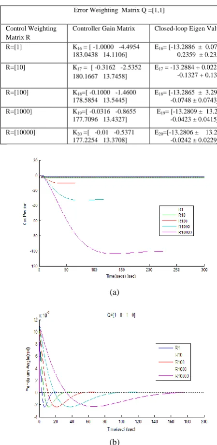
[image:4.595.313.522.148.681.2]Case Study – IV: For the case study-IV the error weighting matrix Q is kept constant whereas control weighting matrix R is varied and the results obtained are shown in Table .4
Table.4: Effect of Varying Control Weighting Matrix R on the Dynamic Performance of the System
Error Weighting Matrix Q =[1,1]
Control Weighting Matrix R
Controller Gain Matrix Closed-loop Eigen Values
R=[1] K16 = [ -1.0000 -4.4954
183.0438 14.1106]
E16= [13.2886 ± 0.0751j
-0.2359 ± 0.2356j] R=[10] K17 = [ -0.3162 -2.5352
180.1667 13.7458]
E17 = -13.2884 + 0.0226 j
-0.1327 + 0.1324i
R=[100] K18=[ -0.1000 -1.4600
178.5854 13.5445]
E18= [-13.2865 ± 3.2902j
-0.0748 ± 0.0743j] R=[1000] K19=[ -0.0316 -0.8655
177.7096 13.4327]
E19= [-13.2809 ± 13.2958j
-0.0423 ± 0.0415j] R=[10000] K20 =[ -0.01 -0.5371
177.2254 13.3708]
E20=[-13.2806 ± 13.2961j
-0.0242 ± 0.0229j]
(a)
(b)
Figure 4(a and b):Effect of Varying Control Weighting Matrix R on the Dynamic Performance of the System
7.
DISCUSSION OF RESULTS
From the investigations revealed by dynamic performances of the system illustrated by the figures 1-4, it is inferred that choosing higher values of Q lowers the system tracking error but poses more emphasis on control effort .This ultimately will lead to requirement of more cost as increasing the control effort necessitates larger sized actuators, bigger amplifiers which lead to more power requirement .Increasing the value of Q elements can be compensated by lowering the value of R matrix elements. This will reduce the weightage part on the control vector and will lead to more economic controller design.
8.
CONCLUSION AND FUTURE SCOPE
OF WORK
In the present study, various patterns of open loop and closed loop system eigenvalues are obtained with optimal, sub-optimal controllers designed for the system. For designing the controllers, linear quadratic regulator (LQR) strategy is used. The stability analysis of autonomous wheeled mobile robots (AWMR) is carried out by analyzing the patterns of eigenvalues. In future Intelligent Controllers may be designed and developed for improving the dynamic stability of the AWMR in unstructured environment.
9.
REFERENCES
[1] KoheiWakita,Jian Huang, Pei Di, KosukeSekiyama, and
Toshio Fukuda,“Human-Walking Intention-Based
Motion Control of an Omnidirectional-Type Cane
Robot”, IEEE/ASME Transactions on
Mechatronics, vol. 18, no. 1, pp 285-297, February 2013 [2] Kazuo Tanaka, HiroshiOhtake,, Toshiaki Seo, Motoyasu Tanaka, and Hua O. Wang, “Polynomial Fuzzy Observer Designs:A Sum-of-Squares Approach.” IEEE Transactions on Systems, Man, and Cybernetics—part B: Cybernetics, vol. 42, no. 5,pp 1330-1343, October 2012 [3] ChristianO’Reilly,and RéjeanPlamondon,“A Globally
Optimal Estimator for the Delta Lognormal Modelling of Fast Reaching Movements”, IEEE Transactions on Systems, Man, and Cybernetics—part B: Cybernetics, vol. 42, no. 5,pp 1428-1443, October 2012
[4] Liyuan Li, Shuicheng Yan, , Xinguo Yu, YeowKee Tan and Haizhou Li, “Robust Multiperson Detection and Tracking for Mobile Service and Social Robots”, IEEE Transactions on Systems, Man, and Cybernetics—part B: Cybernetics, vol. 42, no. 5,pp 1398-1413, October 2012
[5] Math Works, User`s guide
[6] SovannaraHak, Nicolas Mansard, Olivier Stasse, and Jean Paul Laumond ,“ReversControl for Humanoid Robot Task Recognition”, IEEE Transactions on Systems, Man, and Cybernetics -part B: Cybernetics, vol. 42, no. 6,1524-1538, December 2012
[7] JuntaoFei and JianZhou, “Robust Adaptive Control of MEMS Triaxial Gyroscope Using Fuzzy Compensator” IEEE Transactions on Systems, Man, and Cybernetics part B: Cybernetics, vol. 42, no.6, December 2012 pp 1595- 1599
[8] Biao Luo and Huai-Ning Wu , “Approximate Optimal Control Design for Nonlinear One-Dimensional Parabolic PDE Systems Using Empirical Eigen functions and Neural Network”, IEEE Transactions on Systems, Man, and Cybernetics—part B: Cybernetics, vol. 42, no. 6,pp 1538-1550, December 2012
[9] Qi Zhou,Peng Shi, Honghai Liu, and
ShengyuanX,“Neural-Network Based Decentralized Adaptive Output-Feedback Control for Large-Scale Stochastic Nonlinear Systems.” IEEE Transactions on Systems, Man, and Cybernetics—part B: Cybernetics, vol. 42, no.6, pp 1608-1620 December 2012
Man, and Cybernetics—part B: Cybernetics, Vol. 42, No. 6, pp 1574-1586, December 2012
[11]AlinDrimusa, GertKootstra b, Arne Bilberg
,DanicaKragic b , “Design of a flexible tactile sensor for classification of rigid and deformable objects. ” Robotics and Autonomous Systems 2012 Elsevier [12]N.M. Abdul Ghani, L.K. Haur, T.P.Yon, F Naim , “Dual
Mode Navigation for Two-Wheeled Robot.” World Academy of Science, Engineering and Technology, vol. 58, pp 278-283, 2011
[13]Enaiyat Ghan, I Ovy, ShakeelSeeraji,S.M.Firdousand MohammadRokonuzzaaman, “A Novel Design Of An Atmega 32 L Microcontroller Based Controller Circuit for The Motion Control Of Robot Arm Actuated by DC Motors”, Journal of selected areas in robotics (JSRC), pp-1-8, April-2011,
[14]UmarFarooq, Muhammed Amar, EitzazulHaq,
MuhammedUsmanAsad,HafizMuhammedAtiq,
“Microcontroller based Neural Network Controlled Low Cost Autonomous Vehicle”, Second International Conference on Machine Learning and Computing, pp 96-100, IEEE-2010
[15]Donglin Wang, SandeepChandana, Renlun He, Jiuqiang Han, Xiangyu Zhu, KeZou and Yong He,“Intelligent Sensor Design in Network based Automatic Control” Second International Conference on Machine Learning and Computing, IEEE-2010
[16]Jia-Sheng Hu, Mi-Ching Tsai, Feng-Rung Hu, and Yoichi Hori , “Robust Control For Coaxial Two-wheeled Electric vehicle”, Journal of Marine Science and Technology, Vol. 18, No. 2, pp. 172-180 ,2010 [17]Aribowo A.G., Nazaruddin Y.Y., Joelianto E., Sutarto
H.Y.,2007, “Stabilization of Rotary Double Inverted Pendulum using Robust Gain-Scheduling Control”, SICE Annual Conference 2007 Sept. 17-20, 2007, Kagawa University, Japan, IEEE.
[18]Cheng Fuyan, Zhong Guomin, Li Youshan, Xu Zhengming, “Fuzzy Control of a Double-Inverted Pendulum”, Fuzzy Sets and Systems no.79 ,1996 pp 315-321.
[19] Wang Luhao, Sheng Z , “LQR-Fuzzy Control for Double Inverted Pendulum” 2010 International Conference on Digital Manufacturing & Automation, pp 900-904, China [20] Lal Bahadur Prasad , Barjeev Tyagi and Hari Om Gupta , “Optimal Control of Nonlinear Inverted Pendulum Dynamical System with Disturbance Input using PID Controller & LQR”, 2011 IEEE International Conference on Control System, Computing and Engineering pp 540-546
[21] Yong Li and Jianchang Liu Yu Wang, “Design Approach of Weighting Matrices for LQR Based on Multi-objective evolution Algorithm”, Proceedings of the 2008 IEEE International Conference on Information and
Automation June 20-23, 2008, pp 1188-1193,
Zhangjiajie , China
[22] Danai Phaoharuhansa and A kira Shimada , “Trajectory Tracking for Wheeled Inverted Pendulum Robot using Tilt Angle Control”, IEEE Transactions on Systems, Man and Cybernetics, vol. 2, pp 4286-4292, 2013 [23] Amir A., Bature, Salinda Buyamin, Mohamed. N.
Ahmad, Mustapha Muhammad, “A Comparison of Controllers for Balancing Two Wheeled Inverted Pendulum Robot, “International Journal of Mechanical & Mechatronics Engineering”, IJMME-IJENS vol:14 no:03 pp -62-69, June 2014
[24] Witold Pawlus, and Hamid Reza Karimi, “Modelling and Control of an Autonomous Mobile robot”, International Science Press, December 2012, pp 125-154
Appendix A DATA is taken from [24]
Gravity (g) =9.81(m/s2)
f(coefficient of friction of cart) = 0.1 Ns/m Mass of cart Mc = 2 (kg)
Mass of pendulum , Mp = 0.25 (kg) Inertia of the pendulum, Ip= 0.0233 (kg-m2)
Length to the body's center of mass, l= 0.1 (m)