Embedded Controller Integrated Into a WSN for Control
Motor Speed Using WiFi Network
Sathish Kumar.S, Sudhakaran.M, M.E,(Ph.D), Dr.Seyezhai.R
*
PG Scholar, Department of EEE, Ganadipathy Tulsi’s Jain Engineering college, Vellore-632102. **
Associate Professor, Department of EEE, Ganadipathy Tulsi’s Jain Engineering college, Vellore-632102. **
Associate Professor, Department of EEE, Siva Subramani Nadar College of Enginnering, Kalavakkam
Abstract- A method to monitoring the torque and efficiency in
induction motor in real time by employing wireless sensor networks (WSNs). In Industries most of the mechanical works are done by motors among them 90% are induction motors. A controller unit (stellaries) is employed for acquiring electrical signals from the motor in a non invasive manner, and then performing local processing for torque and efficiency estimation. These values are calculated by the controller unit which are transmitted to a monitoring unit through a WiFi based WSN. At the base unit, various motors can be monitored in real time.
Index Terms- Induction motor, arm cortex-M4, IEEE 802.11g,
condition monitoring, torque and efficiency estimation.
I. INTRODUCTION
n an industrial environment, mechanical systems driven by electric motors are used in most production processes, accounting for more than two-thirds of industry electricity consumption. Regarding the type of motors usually employed, about 90% are three-phase ac induction based, mainly due to its cost effectiveness and mechanical robustness. Torque is one of the main parameters for production machines. In several industry sectors, torque measurements can identify equipment failure, which makes their monitoring essential in order to avoid disasters in critical production processes (e.g., oil and gas, mining, and sugar and alcohol industries). For decades, researchers have studied methods and systems for determining the torque in rotating shafts. There are basically two lines of study: direct torque measurement on the shaft, and estimated torque measurement from motor electrical signal. In most cases, the methods for direct torque measurement on the shafts are the more accurate. However, they are highly invasive, considering the coup ling of the measurement instrument between the motor and the load. Moreover, some of these techniques still have serious operational challenges. The estimated torque from the motor’s electrical signals (i.e., current and voltage) makes the system less invasive, but it is less accurate when compared to direct measurement systems. There are problems, such as noise in signal acquisition, those related to numerical integration, and low levels of voltage signals at low frequencies. However, in many cases, high precision is not critical, and low invasiveness is required. There are different methods to measure efficiency in induction motors, which are based on dynamometer, duplicate machines, and equivalent circuit approaches. However, their application for in-service motors is impractical, becausit requires
interrupting the machine’s operation to install the instruments. There are some simple methods for in-service efficiency estimation, like the nameplate method, the slip method, and the current method. These methods present as the main limiting factors the low accuracy, estimative based on nominal motor data and the need of typical efficiency-versus-load curves. In the ORMEL96 method, the efficiency is obtained from an equivalent circuit that is generated from the motor nameplate and the rotor speed measurement.
Hsu and Scoggins presented the air-gap torque[1] (AGT) for energy efficiency estimation. In, the AGT is also used to measure efficiency in a much less invasive manner. The AGT[1] method can be employed without interrupting the motor operation and it is not based on the motor nameplate. This method generally is more accurate than the other methods described earlier. In this study, the AGT [2]method was used for the estimation of the motor shaft torque and efficiency[3], because it is the non invasive method for determining torque and efficiency that has less uncertainty[4]. Traditionally, energy monitoring and fault detection in industrial systems are performed in an offline manner or through wired networks[5]. The installation of cables and sensors usually has a higher cost than the cost of the sensors themselves. Besides the high cost, the wired approach offers little flexibility, making the network deployment and maintenance a harder process.
In this context, wireless networks present a number of advantages compared to wired networks as, for example, the ease and speed of deployment and maintenance, and low cost. In addition to that, wireless sensor networks(WSNs) provide self organization and local processing capability. Therefore, these networks appear as a flexible and inexpensive solution for building industrial monitoring and control systems. Never the less, the use of WSNs[6], when developing automation systems for industrial environments, presents a number of challenges that should be faced. Wireless networks have unreliable communication links, what can be aggravated with noise and interference in the communication spectrum range[7]. Studies on the application of WSNs in industrial environments, aiming at replacing wired systems, have been extensively explored in recent years. This paper presents an embedded system for determining torque and efficiency in industrial electric motors by employing WSNs technology. For a set of electric motors, current and voltage measures are gathered for later processing into an embedded system. Torque and efficiency results are then sent to a base unit for real-time monitoring. This way, preventive action can be taken whenever low-efficiency motors are detected and in cases of torque outbreaks.
II. BLOCKDIAGRAM
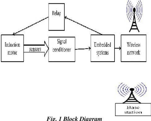
[image:2.612.47.291.152.347.2]Sensor sense the signal that signal strength is increase in signal conditioner that signal is process to the controller and relay is controlled. This information sent to the base station through a wireless sensor network. The controller are using arm cortex M4 family, they are monitoring the values by quick processing fast response in this controller.
Fig. 1 Block Diagram
III. SYSTEMDESCRIPTION
The WSN proposed in this paper. End nodes are composed by the embedded systems located close to the electric motors. The values of motor voltage and current are obtained from the sensors, and the embedded system performs the processing for determining the values of torque, speed, and efficiency. Information obtained after the processing are transmitted to the base station through the WSN. Depending on the distance between end nodes and the coordinator, it may not be possible to achieve direct communication, due to the radio’s limited range and the interference present on the environment, among other factors. Therefore, the communication among nodes and coordinator can be done with assistance of router. For current measurement, Hall Effect sensors are employed due to their robustness and non invasiveness. Transformers with grain-oriented core are used to measure the voltage between phases, which provide the voltages in the secondary and primary without delay. The acquisition and data processing unit (ADPU) is responsible for data acquisition and conversion, besides the data processing. The printed boards power supply supplies the current and voltage for the sensors, the IEEE 802.11 transceiver, and the ADPU. The main element of the ADPU is a PIC16F877A, which is a digital signal controller designed for applications that require high processing capacity. It has two integrated ADC, which perform simultaneous acquisition of the voltage and current sensors. The input/output channels can be used for user interface, and possible connections to auxiliary sensors and actuators. The values of torque and motor efficiency are transmitted using the IEEE 802.11 Transceiver. We have used an MRF24J40
transceiver and the PIC is accomplished using a Serial Peripheral Interface Bus. The internal operation of the embedded system is illustrated by the activity diagram. When the system starts, the embedded system parameters are configured. These parameters include the wireless network settings (e.g., address, channel), and the ADC settings. To obtain good accuracy from a simple numerical integration method, such as trapezoidal (used to implement the algorithm), a sample rate greater than 2 kHz [31] should be used. In our system, we set the ADC to operate with 3 kHz and 10 bits of resolution. After the first step, the system connects to the WSN. The embedded system only begins to acquire and process data after successfully connecting to a coordinator operating in the same channel. Then, the system gets into the acquisition loop, processing, and transmitting data, which is repeated until the system shuts down. The voltage and current values, after acquired, must be adjusted to reflect the real values measured from the sensors. After that, the algorithm is executed to compute the AGT, according to (1). After that, the losses are removed, and the shaft torque is estimated according to (2). Using the shaft torque values, the system estimates the motor speed and efficiency. The embedded systems were configured to calculate a set of 360 values (2 bytes each) of torque and efficiency, and then transmit these values aggregated into 20 packets with 72 bytes of payload each. The time necessary to acquire the signals and calculate the 360 values of torque and efficiency is about 11 s (6 s to acquire 360 cycles of current and voltage, and 5 s to perform the calculations). Thus, the system transmits data in burst mode, spending only about 8% of the time transmitting data, at a rate of 20 packets/s (about 14 kb/s, including control overhead).
IV. HYPERTERMINALSOFTWARE
Most Spectracom products have an RS-232 Com port to configure selectable parameters and retrieve operational status and performance logs. Connect the Spectracom RS-232 Com (Setup) port to a computer using a one to one pinned DB9 serial cable. This cable has a DB9 male on one end and a DB9 female on the other end. Do not try to use a null modem cable with gender changers to get the “correct” pin configuration. A null modem cable reverses transmit and receive lines and therefore will not work in this application. To allow communication the computer must be running a terminal emulation program such as hyperterminal
V. HARDWAREDESCRIPTION
carrying hall element perpendicular to the current flow a Lorentz force acts on the current due to which a voltage called all voltage(Vh) is generated perpendicular to both the current and the magnetic field. This voltage is very small (in uV) and needs amplification.
Relay Selection Relays (and switches) come in different configurations. The most common are shown to the right. Single Pole Single Throw (SPST) is the simplest with only two contacts. Single Pole Double Throw (SPDT) has three contacts. The contacts are usually labelled Common (COM), Normally Open (NO), and Normally Closed (NC). The Normally Closed contact will be connected to the Common contact when no power is applied to the coil. The Normally Open contact will be open (i.e. not connected) when no power is applied to the coil. Ex: If you want to turn on the AC unit with a 12VDC power supply get a 12VDC coil. Note: Coils will be rated for either AC or DC operation. WiFi is a facility allowing computers, smart phones, or other devices to connect to the Internet or communicate with one another wirelessly within a particular area. Wi-Fi is increasingly becoming the preferred mode of internet connection all over the world. To access this type of connection, one must have a wireless adapter on their computer. Typically, DAQ plug-in boards are general-purpose data acquisition plug-instruments that are well suited for measuring voltage signals. However, many real-world sensors and transducers output signals that must be conditioned before a DAQ board or device can effectively and accurately acquire the signal.
Wi-Fi provides wireless connectivity by emitting frequencies between 2.4GHz to 5GHz based on the amount of data on the network. Areas which are enabled with Wi-Fi connectivity are known as Hot Spots. One can use advanced software like Wireless on to detect and request connection to Hotspots. Required settings are properly installed. Signal Conditioner PC-based data acquisition (DAQ) systems and plug-in boards are used in a very wide range of applications in the laboratory, in the field, and on the manufacturing plant floor. This front-end pre-processing, which is generally referred to as signal conditioning, includes functions such as signal amplification, filtering, electrical isolation, and multiplexing. In addition, many transducers require excitation currents or voltages, bridge completion, linearization, or high amplification for proper and accurate operation. Therefore, most PC-based DAQ systems include some form of signal conditioning in addition to the plug-in DAQ board and personal computer. Base Station proposed IS, embedded software development for the CPU contains 4 tasks and 4 interruptions.4 tasks consist of sensing data collection from FLS, data elementary processing, significant malfunction scan and user interface response. Sensing data collection indicates collecting dynamic sensing data and automatically storing these data in the IS. Data elementary processing means to process the raw sensing data to acquire the required typical data, such as the maximal/minimal/average value, the active/reactive power and the system efficiency, etc...Significant malfunction scan is to detect the severe malfunctions, such as short circuit, missing phase and over current, and report them. Keyboard interruptions guarantees that the external input can be responded to CPU in time.
VI. SIMULATIONRESULTS
Proteus is software for microprocessor simulation, schematic capture, and printed circuit board (PCB) design. It is developed by Lab centre Electronics. The Proteus Design Suite is wholly unique in offering the ability to co-simulate both high and low-level micro-controller code in the context of a mixed-mode SPICE circuit simulation. With this Virtual System Modelling activity, you can transform your product design cycle, reaping huge rewards in terms of reduced time to market and lower costs of development. If one person designs both the hardware and the software then that person benefits as the hardware design may be changed just as easily as the software design.
Fig.2 Motor Running Condition
In larger organizations where the two roles are separated, the software designers can begin work as soon as the schematic is completed; there is no need for them to wait until a physical prototype exists. Fig 2 normal motor running condition. providing input values to controller as motor convenient then motor can run in normal condition.
Fig.3 Malfunction Monitor
off at a fast pace. The longer the switch is on compared to the off periods, the higher the power supplied to the load.
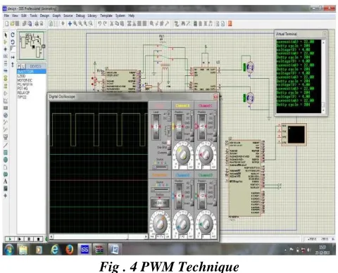
[image:4.612.47.287.170.364.2]The PWM switching frequency has to be much faster than what would affect the load, which is to say the device that uses the power. Typically switchings have to be done several times a minute in an electric stove, 120 Hz in a lamp dimmer, from few kilohertz (kHz) to tens of kHz for a motor drive and well into the tens or hundreds of kHz in audio amplifiers and computer power supplies. When data are monitored.
Fig . 4 PWM Technique
to the virtual terminal, in that some error are high voltage or current and any other faults occurred means they show in virtual terminal by system terminated. Then the relay is tripping the circuit.
VII. CONCLUSION
An embedded system integrated into a WSN for online speed control, torque and efficiency monitoring in induction motors. The calculations for estimating the targeted values are done locally and then transmitted to a monitoring base unit through an IEEE 802.11 WSN. Even with the difficulties in data transmission using the WSN in some scenarios, the system was able to provide useful monitoring information, since all processing is done locally (i.e., only the information already computed is transmitted over the network). Without local processing, it might be impossible to use the WSN technology for this particular application, considering an unreliable transmission medium. Allied to the local processing capacity, other techniques can be developed to mitigate interference in those environments, leading to better communication performance. In future multiple of motors can be used in real time. To identified the fault condition by non invasive manner online monitoring process.
REFERENCES
[1] Abel C. Lima-Filho “Embedded system integrated into a wireless sensor network for online dynamic torque and efficiency monitoring in induction motors” Ieee/asme transactions on mechatronics, vol. 17, no. 3, june 2012 .
[2] V. C. Gungor and G. P. Hancke, “Industrial wireless sensor networks: Challenges, design principles, and technical approaches,” IEEE Trans. Ind. Electron., vol. 56, no. 10, pp. 4258–4265, Oct. 2009.
[3] K. Gulez, A. A. Adam, and H. Pastaci, “A novel direct torque control algorithm for IPMSM with minimum harmonics and torque ripples,” IEEE/ASME Trans. Mechatronics, vol. 12, no. 2, pp. 223–227, Apr. 2007. [4] F. Salvadori, M. de Campos, P. S. Sausen, R. F. de Camargo, C. Gehrke, C.
Rech, M. A. Spohn, and A. C. Oliveira, “Monitoring in industrial systems using wireless sensor networkwith dynamic power management,” IEEE Trans. Instrum. Meas., vol. 58, no. 9, pp. 3104–3111, Sep. 2009.
[5] B. Lu and V. C. Gungor, “Online and remote motor energy monitoring and fault diagnostics using wireless sensor networks,” IEEE Trans. Ind. Electron., vol. 56, no. 11, pp. 4651–4659, Nov. 2009.
[6] B. Lu, T.G.Habetler, and R. G. Harley, “Asurvey of efficiency-estimation methods for in-service inductionmotors,” IEEE Trans. Ind. Appl., vol. 42, no. 4, pp. 924–933, Jul./Aug. 2006.
[7] S. B. Ozturk and H. A. Toliyat, “Direct torque and indirect flux control of brushless DC motor,” IEEE/ASME Trans. Mechatronics, vol. 16, no. 2, pp. 351–360, Apr. 2011. A. Willig, K. Matheus, and A. Wolisz, “Wireless technology in industrial networks,” in Proc. IEEE, vol. 93, no. 6, 1130– 1151, 2005.
[8] H. Li, M. Syed, Y.-D. Yao, and T. Kamakaris, “Spectrum sharing in an ISM band: Outage performance of a hybrid DS/FH spread spectrum system with beamforming,” EURASIP J. Adv. Signal Process., 2009.
[9] J. Huang, G. Xing, G. Zhou, and R. Zhou, “Beyond co-existence: Exploiting WiFi white space for zigbee performance assurance,” in Proc. IEEE Int. Conf. Netw. Prot., 2010, pp. 305–314.
[10] L. Cao, W. Jiang, and Z. Zangh, “Network wireless meter reading system based on zigbee technology,” in Proc. IEEE Control Decis. Conf., 2008, pp. 3455–3460.
[11] B. Fette, R. Aiello, P. Chandra, D. Dobkin, D. Bensky, D. Miron, D. Lide, F. Dowla, and R. Olexa, RF & Wireless Technologies: Know It All. Amsterdam, The Netherlands: Elsevier, 2007.
AUTHORS
First Author – S.Sathish Kumar He
received B.E degree in Electrical and Electronics Engineering from Arunai College of Engineering, Tiruvanamalai in 2009 and M.E pursing in Embedded System technologies from Anna University in 2014. His research interests are
Communicating the Networks, Induction motor Drives, Embedded controllers., Email:
Second Author – M.Sudhakaran He
received B.E degree in Electrical and Electronics Engineering from Sapthagiri College of Engineering, Dharamapuri in 1998 and M.E degree in Power System from Annamalai University in 2004. His research interests are Multilevel Inverter, Induction motor Drives and Neural Networks., Email:
Third Author – R.Seyezhai obtained her
University, Chennai. She has been working in the teaching field for about 15 Years. She has published 150 papers in International Journals and International Conferences in the area of Power Electronics & Drives. Her areas of interest include SiC Power
Devices, Multilevel Inverters, Modeling of fuel cells, Design of Interleaved Boost Converter, Multilport DC-DC Converter and control techniques for DC-DC Converter., Email: