Application of Distribution Static Compensator
(D-STATCOM) to Voltage Sag Mitigation
H. Molavi
1,*, M. M. Ardehali
21Institute of technology, Sharif University, Tehran, Iran
2Electrical Department, Amirkabir University, Tehran, Iran
*Corresponding Author: [email protected]
Copyright © 2013 Horizon Research Publishing All rights reserved.
Abstract
This paper presents a study of a D-STATCOM (Distribution Static Compensator) used for mitigating voltage sag. The basic idea of the voltage sag mitigation, using a D-STATCOM is to dynamically inject a current of desired amplitude, frequency and phase into the grid line. The proposed method extracts the active and reactive parts of the positive- and negative-sequence component for generating reference values of current that need to be injected into the point of connection D-STATCOM in order to compensate the voltage errors. The proposed method offers structural simplicity and less calculation complexity. Simulation results indicate that this method is effective and D-STATCOM has good performance to mitigate the voltage sag.Keywords
Voltage Sag, D-STATCOM, D-Q Controller1. Introduction
Voltage sag is a reduction between 10 and 90%in rms voltage with a duration between 0.5 cycles and 1 min (although voltage sag depth and duration typically range from 80 to 90% and 0.5 to 30 cycles, respectively) [1]. Voltage sags are the most important power quality (PQ) problems that many industries and utilities face it. Among different types of disturbances occurring in power system, voltage sag is known to produce the most devastating impact on the loads [2]. Studies show that 92% of all disturbances in the electrical power distribution systems are voltage sags, transients, and momentary interruptions [3, 4]. Voltage sags are not tolerated by sensitive equipment used in modern industrial plants such as process controllers; programmable logic controllers (PLC), adjustable speed drive (ASD) and robotics [5]. Various methods have been applied to reduce or mitigate voltage sags. The conventional methods are by using capacitor banks, introduction of new parallel feeders and by installing uninterruptible power supplies (UPS).
Recently D-STATCOM has emerged as a promising device to provide not only for voltage sag mitigation but also for a host of other power quality solutions such as voltage stabilization, flicker suppression, power factor correction, and harmonic control [6]. D-STATCOM is a shunt connected device that generates a balanced set of three sinusoidal voltage or current at the fundamental frequency [7]. DSTATCOM configuration consists of a VSC that converts voltage across the storage device into a set of three-phase ac output voltages. These voltages are in phase and coupled with the ac system of network through the reactance of the coupling transformer [8]. In [9], a repetitive- based controller for a D- STATCOM is presented that compensate reactive power, but it offers more calculation complexity. [10], presented a D-STATCOM control algorithm which enables seperate positive and negative sequence currents, but the presented method needs more time than the control method that perenetd in this paper.
This paper presents a study of a D-STATCOM (Distribution Static Compensator) used for mitigating voltage sag. The control object of D-STATCOM is that the line voltages at the normal operation only include positive sequence. The control method is made up of DC voltage controller and current controller.
The rest of the paper is organized as follows: section II present the D-STATCOM description. Section III explains the control method. The obtain simulation results are discussed in section IV and finally, section V concludes the paper.
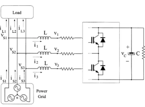
2. Description of the D-STATCOM
Figure 1. schematic representation of D-STATCOM
In the unbalanced conditions the line voltage is equal to the sum of negative and positive sequence so we will have:
1
2
cos( )
2
cos(
)
s sp sn n
V
=
V
ω
t
+
V
ω ϕ
t
+
(1)2
2
2
2 cos(
) 2 cos(
)
3
3
s sp sn n
V
=
V
ω
t
−
π
+
V
ω
t
+
π
+
ϕ
(2)1
2
cos(
2
3
)
2
cos(
2
3
)
s sp sn n
V
=
V
ω
t
+
π
+
V
ω
t
−
π
+
ϕ
(3)In the above equation
V
sp andV
Sn are the RMS of positive and negative sequence component of the line voltages, respectively. By applying Kirchoff’s Voltage Law (KVL) we will have:1
1 1 1
f s
di
L
R i V
V
dt
+
=
−
(4)2
2 2 2
f s
di
L
R i V
V
dt
+
=
−
(5)3
3 3 3
f s
di
L
R i V
V
dt
+
=
−
(6)Applying Kirchoff’s Current Law (KCL) satisfy the fallow equations:
1 1 1
s L
i
=
i
+
i
(7)2 2 2
s L
i
=
i
+
i
(8)3 3 3
s L
i
=
i
+
i
(9) By combining the Eqs (4-6) with Eqs (7-9) we will have:1 1
1 1 1 1
s L
s f s f L
di
di
L
L
V
V R i
R i
dt
=
dt
+
− −
+
(10)2 2
2 2 2 2
s L
s f s f L
di
di
L
L
V
V R i
R i
dt
=
dt
+
− −
+
(11)3 3
3 3 3 3
s L
s f s f L
di
di
L
L
V
V
R i
R i
dt
=
dt
+
− −
+
(12)The model transformed from 'abc' frame into 'dq' frame is given by:
1 1
sd sq sd d Lq
sq sd sq q Ld
Ld sd ld
f f
Lq sq lq
i
i
V
V
i
d
L
L
L
i
i
V
V
i
dt
i
i
i
d
L
i
R
i
R
i
dt
ω
−
ω
−
= −
+
−
+
+
−
+
(13) In (13) the parasite resistance Rf is very small so that we have:
0
ldf
lq
i
R
i
=
(14)The switch frequency is much higher than line frequency, so the changes of
i
ld andi
lq in a switch period can beomitted. Thus, we have:
0
ld lq
i
d
L
i
dt
=
(15)According to (14) and (15) we have:
sd sd sd sq Lq d
f
sq sq sq sd ld q
i
i
V
i
i
V
d
L
i
R
i
V
L
V
i
i
dt
ω
− +
+
=
−
−
−
(16)
3. Control Method
3.1. Extraction the Positive Component
In order to extraction the positive component; first consider the line voltage by a 3π delay, as the below:
1 1
2 cos(
3
) 2 cos(
3
)
s sp sn n
V
−=
V
ω
t
−
π
+
V
ω ϕ
t
+ −
π
(17)2 2
2 cos(
)
2 cos(
3
)
s sp sn n
V
−=
V
ω π
t
− +
V
ω ϕ
t
+ +
π
(18)3 3
2
cos(
3
)
2
cos(
)
s sp sn n
V
−=
V
ω
t
+
π
+
V
ω ϕ π
t
+
−
(19)The negative component of
V
s s1 2− andV
s s2 3− are equal to:1 2
(
1 3 3)
s s s s
V
−V V
[image:2.595.64.297.69.241.2]2 3
(
3 1 1)
s s s s
V
−V V
−
= −
+
− (21)Eq (22) shows the relationship between line to line negative voltage and line to neutral negative voltages
1 1 2 2 2 3 3
2
1
1 1 1
3
1
2
s s s s s s sV
V
V
V
V
− − − − − − −
=
−
−
−
(22)The line voltages are equal to sum of negative and positive sequence, so that :
s s s
V
+=
V V
−
− (23) Finally we can calculate the positive component by Eq (23).3.2. Application of ‘dq’ Controllers
The proposed D-STATCOM controller consists of current and dc voltage controller. The dc voltage controller regulates the dc voltage at the required level and the current controller forces the D-STATCOM current to follow the references.
The transformation matrix from ‘s1s2s3’ into ‘dq’ frame can be defined as follows [11]:
2 2
cos( ) cos( ) cos( )
2 3 3
2 2
3 sin( ) sin( ) sin( )
3 3
T
θ θ π θ π
θ θ π θ π
+ − = − − + − − (24)
We need the transformation of the Eqs (23) into conventional stationary
'
αβ
'
coordinates and the transformation matrix is equal to [11]:1
2
3
1
1
1
2
2
2
3
0
3
3
2
2
s s sV
x
V
x
V
α β + + +
−
−
=
−
(25)From the Eq (25) we will have:
2 2
cos( )
t
x
x
x
α
α β
ω
=
+
(26)2 2
sin( )
t
x
x
x
β
α β
ω
=
+
(27)We need to decouple
i
d andi
q for proper control design. Decoupling can be satisfied by introducing new parametersd
u
andu
q.d sd d q
u
=
V
−
V
+
ω
L i
(28)q sq q d
[image:3.595.53.548.56.692.2]u V V
=
− −
ω
L i
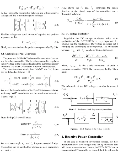
(29)Fig.2 shows the
i
d andi
q controller; the transferfunction of the closed loop of the controllers can be illustrated as below:
2
1
(
)
c r P I
cloop
f c r
P I
f
G G
K s K
G
R
G G
S
K s K
L
+
=
=
+
+
+
+
(30)3.3. DC Voltage Controller
Regulation the DC voltage at desired value in the application of the D-STATCOM is very important. It is obvious that the regulation of DC voltage is carried out by charging and discharging of the capacitor. The relationship between
V
dc andi
d can be written as the below:2 2
( )
2( )
3
2
dc dc d PCC d
dc dc
d V
V
v
i
dt
= −
R C
+
CR
− (31)where,
v
d PCC− is the d-axis component of point ofcommon connection (PCC). By rearranging the Eq (30) we have:
2 2
( )
dc2( )
dcdc
d V
V
K
dt
+
R C
=
(32) [image:3.595.57.557.431.641.2]The schematic of the DC voltage controller is shown in Fig.3.
Figure 2. Equivalent block diagram of d-q controllers
Figure 3. Block diagram of DC voltage controller
4. Reactive Power Controller
transforming into dq synchronous reference frame results in dc-quantities and these dq feedback signals allow in control design reactive power control. Transformation of three-phase balance voltages with unity magnitude into the positive and negative dq synchronous reference frame results in dc-quantities with following values.
0 ,
0
d q
v
+=
pu v
+=
pu
0 ,
0
d q
v
−=
pu v
−=
pu
where
v v
d+,
q+ are the positive sequence of voltage and,
d q
v v
− −are the negative sequence of voltage. The controller’s operation are based on above values, in other words the voltage sag in power network can be corrected by regulating positive and negative sequences to the above values.
5. Simulation Results
5.1. Test System
The simulation system is constructed according to Fig. 1 with the proposed compensation method. The circuit parameters are Vs =380V , leakage reactance of each H-bridge L=10.1mH , resistance of each H-bridge
ohm
R=0.18 and C=440
µ
F , fs =50Hz. During the simulation, the unbalance load is operated with between phase A-C and between phases A-B.5.2. Results and Discussions
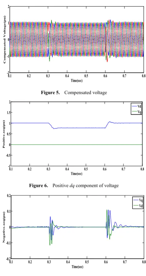
[image:4.595.312.549.69.515.2]Application of D-STATCOM to voltage sag mitigation is simulated in MATLAB/SIMULINK. Figure.4 shows the uncompensated voltage, from Fig.4 can be seen that the balanced sag (70%) occurs at 0.3 (sec). Fig.5 shows the compensated voltage which the voltage remains at 1 pu during the sag. Fig.6 shows the positive dq component and Fig.7 shows the negative dq component.
Figure 4. Uncompensated voltage
Figure 5. Compensated voltage
Figure 6. Positive dq component of voltage
Figure 7. Negative dq component of voltage
6. Conclusion
This paper presented the operation of D-STATCOM to voltage sag mitigation. In order to mitigate voltage sag the positive and negative sequence is separated and the proposed method extracts the active and reactive parts of the positive- and negative-sequence component for generating reference values of current that need to be injected into the point of connection D-STATCOM in order to compensate the voltage errors. Simulation results show that D-STATCOM can be used for voltaje sag mitigation and has a good performance under voltaje sag.
REFERENCES
[1] R. C. Dugan, M. F. McGranaghan and H. W. Beaty,
0.1 0.2 0.3 0.4 0.5 0.6 0.7 0.8
-2 -1 0 1 2
Time(hour)
U
nc
om
pe
ns
a
te
d vol
ta
ge
(pu)
0.1 0.2 0.3 0.4 0.5 0.6 0.7 0.8 -2
-1 0 1 2
Time(sec)
C
o
m
pe
ns
a
te
d V
o
lt
a
g
e
(pu)
0.1 0.2 0.3 0.4 0.5 0.6 0.7 0.8 -1
-0.5 0 0.5 1 1.5 2
Time(sec)
P
o
si
ti
v
e
.s
e
q(
pu)
Vd Vq
0.1 0.2 0.3 0.4 0.5 0.6 0.7 0.8 -0.2
-0.1 0 0.1 0.2
Time(sec)
N
e
g
a
ti
v
e
.s
e
q(
pu)
[image:4.595.61.295.585.728.2]“Electrical power systems quality,” McGraw Hill Companies, Inc., 1996.
[2] A. Ghosh, G. Ledwich, Power quality enhancement using
custom power devices, Kluwer Academic Publishers, 2002, ISBN: 1402071809.
[3] T.A. Short, Electric Power Distribution Handbook, CRC
Press, 2004.
[4] F. Shahnia, R. Majumder, A. Ghosh, G. Ledwich, F. Zare,
“Voltage imbalance analysis in residential low voltage distribution networks with rooftop PVs” Elsevier, Electric Power Systems Research, Vol. 81, Issue 9, September 2011, pp 1805-1814.
[5] S. H. Hoseini, A, Nazarlu, E. Ebrahimi, “Application of
D-STATCOM to Improve Distribution System Performance with Balanced and Unbalanced Fault Conditions” Electric Power and Energy Conference (EPEC), 2010 IEEE.
[6] Y.Liang and C.O.Nwankpa, "A new type of STATCOM
based on cascading voltage-source inverters with phase-shifted unipolar SPWM," IEEE Trans. Industry Applications, Vol.35, No.5, Sept.Oct. 1999, pp.1118-1123.
[7] N.G. Hingorani and L. Gyugyi, “Understanding FACTS:
Concepts and Technology of Flexible AC Transmission Systems”, 1st edition, The Institute of Electrical and Electronics Engineers, 2000.
[8] D. Shen, W. Liu and Z. Wang, “Study on The Operation
Performance of D-STATCOM Under Unbalanced and Distorted System Voltage,” IEEE Power Engineering Society Winter Meeting., pp. 2630-2635.
[9] G. Escobar, A.A. Valdez, “A repetitive-based controller in
stationary reference frame for D-Statcom in unbalanced operation”, IEEE ISIE, July 2006.
[10] B. Blazic, I. Papic, “Improved D-StatCom Control for
Operation With Unbalanced Currents and Voltages” IEEE TRANSACTIONS ON POWER DELIVERY, VOL. 21, NO. 1, January 2006.
[11] B.Blazic, I.Papic, “A new mathematical model and control of