Journal of Theoretical and Applied Information Technology 10thSeptember 2015. Vol.79. No.1
© 2005 - 2015 JATIT & LLS. All rights reserved.
ISSN:1992-8645 www.jatit.org E-ISSN:1817-3195
PERFORMANCE EVALUATION OF LDPC- AND
TURBO-CODED OFDM BASED ON DMWCST
1,a
SAMEER A. DAWOOD,2,aF. MALEK,1,bM. S. ANUAR,2,bABADAL-SALAM T. HUSSAIN
1School of Computer and Communication Engineering, Universiti Malaysia Perlis (UniMAP), Pauh Putra, 02600, Arau, Perlis, Malaysia
2School of Electrical Systems Engineering, Universiti Malaysia Perlis (UniMAP), Pauh Putra, 02600, Arau, Perlis, Malaysia
E-mail: 1,[email protected],2,[email protected],1,[email protected], 2,b[email protected]
ABSTRACT
In this paper, low-density parity-check (LDPC) codes and turbo codes (TCs) are proposed to improve the bit error rate (BER) performance of a new orthogonal frequency-division multiplexing (OFDM) system based on discrete multiwavelet critical-sampling transform (DMWCST). The use of channel coding in an OFDM based on the DMWCST (OFDM-DMWCST) system is useful in providing the desired performance at high data rates. The proposed systems have been tested according to different code rates and mapping schemes over additive white Gaussian noise, flat fading, and frequency-selective fading channels. The decoding technique used in the simulation for LDPC codes and TCs was iterative decoding because this method provides maximum efficiency at high iterations. Simulation results reveal that the coded OFDM-DMWCST system achieves large coding gain with low BER. Thus, this system offers a high data rate under wireless communication channels. Furthermore, the LDPC-coded OFDM-DMWCST system performs better than turbo-coded OFDM-DMWCST system.
Keywords: OFDM, LDPC codes, turbo codes, multiwavelet critical-sampling transform, data rate, wireless channels.
1. INTRODUCTION
In the 4G communication systems the high-bit-rate transmission is required. Orthogonal frequency division multiplexing (OFDM) provides an efficient means to handle high-speed data streams on a multipath fading environment that causes inter-symbol interference (ISI) [1]. OFDM system divides the total available bandwidth into a number of narrowband orthogonal subcarriers to achieve frequency flat fading [2, 3].
Traditional OFDM systems use inverse fast Fourier transform (IFFT) and fast Fourier transform (FFT) at the transmitter and receiver, respectively, to multiplex the signals and transmit them simultaneously over a number of subcarriers [4]. Using cyclic prefix (CP) technique in traditional OFDM systems, the ISI is effectively removed [5]. However, the CP reduces the power efficiency and data throughput.
Many researchers proposed the use of the discrete wavelet transform (DWT) instead of FFT
to improve the bit-error rate (BER) performance and reducing the effect of using CP in OFDM systems [6-8]. The main difference between FFT and DWT is that the FFT uses the sine and cosine as a basis functions, but the DWT uses the wavelet function and scaling function as a basis functions.
Multiwavelet transform is a new concept proposed recently [9-11]. It is designed to possess symmetry, orthogonality and higher order of approximation simultaneously, which is impossible for scalar wavelet [9].
Journal of Theoretical and Applied Information Technology 10thSeptember 2015. Vol.79. No.1
© 2005 - 2015 JATIT & LLS. All rights reserved.
ISSN:1992-8645 www.jatit.org E-ISSN:1817-3195
In a frequency-selective fading channel, certain subcarriers of OFDM may be completely lost because of the deep fades. Hence, although most subcarriers may be detected without errors, the overall BER will be largely dominated by a few subcarriers with the smallest amplitudes. To avoid this domination by the weakest subcarriers, forward-error correction coding (often called channel coding) is essential. Error-correcting code is a method of adding redundancy to information in a controlled manner to provide the receiver with the ability to detect and correct the errors that occurred in the transmission [13].
In 1993, Berrou et al. [14] proposed turbo codes (TCs), which are implemented by using two parallel concatenated convolutional codes (PCCCs) with an interleaver and decoder by using an iterative technique. These codes are capable of operating near Shannon capacity on additive white Gaussian noise (AWGN) channels.
In Refs. [15–17], TCs were used to improve the performance and throughput of traditional OFDM systems over wireless communication channels.
Low-density parity-check (LDPC) codes were proposed by Gallager [18] in 1962. The LDPC codes attracted attention after their reinvention by Mackey and Neal [19] because these codes are
closest to Shannon’s limit performance with low
decoding complexity.
LDPC codes were used in coding traditional OFDM systems [20] to improve the BER performance of the system. The performance of this coding scheme was worse than that of TC on an AWGN channel but better than that of TC on a frequency-selective fading channel. Ref. [21] proposed an LDPC-coded OFDM-DWT system and found that the LDPC codes perform worse than TCs on the Rayleigh fading channel. Anwar et al. [22] presented a BER performance comparison for LDPC-coded and turbo-coded OFDM systems over Stanford University Interim multipath channel models and found that TC performs better for small number of iterations and converged faster than LDPC codes; however, LDPC demonstrated better performance after the convergence of iterations. The computational complexity of LDPC-coded OFDM system was also lower than that of a turbo-coded OFDM (TC-OFDM) system. A comparison between the BER performance of TC and LDPC codes based on traditional OFDM systems in the Nakagami fading channel was presented in [23]. The results show that the error performance of LDPC codes was better than that of TCs.
In this paper, the LDPC codes and TCs are applied to an OFDM-DMWCST system to achieve the desired performance at high data rates under AWGN, flat fading, and frequency-selective fading channels. The performance of the coded OFDM-DMWCST system will be evaluated for various code rates and mapping techniques. We have also compared the performance of the coded DMWCST system with the uncoded OFDM-DMWCST system. The proposed systems can be considered the first systems that presented a combination between DMWCST and channel coding by using LDPC and TC in reference to the published works in this area.
This paper is organized in six sections. the next section presents the LDPC codes. A review of turbo codes is given in section 3. The block diagram of coded OFDM-DMWCST system utilizing LDPC or turbo codes is presented and discussed in section 4. The simulation results and their discussion are presented in section 4. Finally the conclusions deduced through the work are given in section 6.
2. LDPC CODES
LDPC codes and their iterative decoding algorithm were proposed by Gallager [18] in 1962. The name of the LDPC codes came from the characteristics of their parity-check matrix that contains only a few ones compared with the amount of zeroes [24]. LDPC codes are defined as codes that use a sparse parity-check matrix with the number of ones per column (column weight) and the number of ones per row (row weight); both of which are small compared with the block length. LDPC codes are classified into two groups, namely, regular and irregular. Regular LDPC codes have a uniform column weight and row weight; otherwise, they are irregular. An LDPC code (N, K) is defined by an M × N parity-check matrix, where K = N-M and the code rate is R = K/N.
LDPC codes can be represented by a Factor Graph or Tanner Graph that contains two types of
nodes: the “bit nodes” and the “check nodes”.
Figure 1, shows an example of the Factor Graph. Each bit node corresponds to a column of a parity-check matrix, which also corresponds to a bit in the codeword. Each check node corresponds to a row of a check matrix, which represents a parity-check equation. An edge between a bit node and a check node exists if and only if the bit participates in the parity-check equation represented by the check node [20].
Journal of Theoretical and Applied Information Technology 10thSeptember 2015. Vol.79. No.1
© 2005 - 2015 JATIT & LLS. All rights reserved.
ISSN:1992-8645 www.jatit.org E-ISSN:1817-3195
[image:3.612.95.295.100.237.2]sum product or belief propagation algorithm, which is implemented by using a factor graph.
Figure 1: Example of factor graph
2.1 Sum Product Algorithm
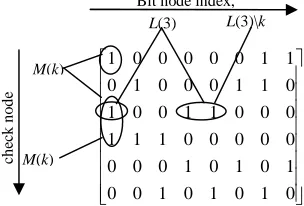
The notations of the sum-product algorithm are described in figure 2. For M(k) denotes the set of check nodes that are connected to the bit node k,
i.e., positions of 1’s in thekthcolumn of the parity-check matrix. L(m) denotes the set of bits that participates in the mthparity check equation, i.e., the
positions of 1’s in the mth row of the parity check matrix. L(m)\k represents the set L(m) with the kth bit excluded and M(k)\m represents the set M(k)
with the mthcheck excluded. qk0m and q1km denote the probability information that the bit node k sends to the check node m, indicating P(xk=0) and
P(xk=1), respectively. rk0mand rk1mdenote the
probability information that the mth check node gathers for the kth bit being 0 and 1, respectively. The a posteriori probability for a bit is calculated by gathering all the extrinsic information from the check nodes that connect to it, which can be obtained by the following iterative procedure [20, 25].
1 0 0 0 0 0 1 1 0 1 0 0 0 1 1 0 1 0 0 1 1 0 0 0 1 1 1 0 0 0 0 0 0 0 0 1 0 1 0 1 0 0 1 0 1 0 1 0
Figure 2: Notation of sum product algorithm
For binary codes, the sum-product algorithm can be performed more efficiently in Log domain, where the probabilities are equivalently characterized by the log-likelihood ratios (LLRs) [25]:
1 0
( ) log( / ),
1 0
( ) log( / ),
1 0
( ) log( / ),
1 0
( ) log( / )
L q q q
k m k m k m
L rm k r r
m k m k
L pk pk pk
L q q q
k k k
(1)
Initialization
Each bit node k is assigned an a priori LLR L(pk). In the case of an equiprobable inputs on a
memoryless AWGN channel:
( | 1) 2
( ) log
2
( | 1)
p yk xk
L pk yk
p yk xk
(2)
where x, y represent the transmitted and received
codewords, respectively, and 2 is the noise variance. For every position (m, k) such that Hmk=
1, where Hmkrepresents the element of the m
th row and the kth column in the parity-check matrix,
( )
L qkm and L rm( k) are initialized as:
( ) ( ) and ( ) 0
L qkm L pk L rmk (3)
Step 1
Each check node m gathers all the incoming information L qk( m)ʼs, and updates the belief on the bit k based on the information from all other bits connected to the check node m.
1 1
( ) 2 tanh tanh( ( ' )
2 ' ( )\
L rm k L qk m k L m k
(4)
Step 2
Each bit node k propagates its probability to all the check nodes that connect to it.
( ) ( ) ( ' )
' ( )\
L qk m L pk L rm k
m M k m
(5)
Step 3
The decoder obtains the total a posteriori probability for the bit k by summing the information from all the check nodes that connect to the bit k.
( ) ( ) ( )
( )
L qk L pk L rm k
m M k
(6)
Hard decision is made on the L(qk). The result of
the hard decision x kˆ is 1 if L(qk) ˂ 0, and 0
otherwise. The resulting decoded output xˆ is checked against the parity-check matrix (H). If
ˆ 0
Hx , the decoder stops and outputsxˆ. Otherwise, it repeats the steps (1-3). The
sum-Check nodes, m
Bit nodes, k
Right Margin 1.25
ch
ec
k
n
o
d
e
in
d
ex
,
m
Bit node index,
kL(3) L(3)\k
M(k)
M(k)
[image:3.612.99.251.535.638.2]Journal of Theoretical and Applied Information Technology 10thSeptember 2015. Vol.79. No.1
© 2005 - 2015 JATIT & LLS. All rights reserved.
ISSN:1992-8645 www.jatit.org E-ISSN:1817-3195
product algorithm sets the maximum number of iterations. If the number of iterations reaches the maximum, the decoder stops and outputs xˆas the result of the hard decision.
3. TURBO CODES (TCs)
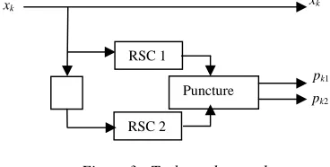
Turbo encoder is built using parallel concatenation of two recursive systematic convolutional (RSC) code of rate 1/2, separated by an interleaver (π). A typical turbo encoder of rate 1/3 is shown in figure 3. The input sequence (xk) is
passed into the input of the first RSC coder, that generates pk1. For the second RSC, the data
sequence is interleaved using random interleaver in which the bits are output in a pseudo-random manner. The interleaved data sequence is passed to a second RSC encoder, generate bit stream pk2. The
output code sequence of the turbo encoder is a multiplexed (and possibly punctured to increase the code rate) stream consisting of systematic code bits xk along with the parity bits of first and second
[image:4.612.94.278.368.461.2]encoders, pk1and pk2.
Figure 3: Turbo code encoder
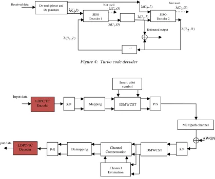
Figure 4, shows the decoding process of turbo codes, which was done by iterative decoding using a soft-input/soft-output (SISO) module based on the Log-MAP (Maximum A Posteriori) algorithm. The symbols λ(.,I) and λ(.,O) at the input and output ports of SISO refer to LLR.
The decoder works in an iterative way. The received sequence from demodulator denote by
λ(C1,I) and λ(C2,I) are fed to the input port of SISO1 and SISO2 respectively at the same time. Here, the number 1 and, 2 is referred to the first and second encoders (or decoders) respectively. At the first iteration,λ(U1,I), andλ(U2,I) are zero. λ(U1,O)
are passed through interleaver (π) that rearranges
the ordering of sequence of symbols in a deterministic manner to obtain λ(U2,I), while
λ(U2,O) are deinterleaved using deinterleaver (π-1) that applies the inverse permutation to restore the original sequence to obtain λ(U1,I) and start the second iteration. At the final iteration, λ(U2,I) and
λ(U2,O) will be added together, and a hard decision
is made on the summation to obtain the estimated information bits.
The readers can refer to [26] for the details of computing SISO Log-MAP algorithm.
4. PROPOSED SYSTEM
The block diagram in figure 5, gives the proposed model for coded OFDM-DMWCST system. Random binary data are generated at the transmitter. These data are encoded by LDPC codes or TCs. The serial coded bits is converted to parallel using serial-to-parallel (S/P) conversion, and mapped according to the mapping technique (in this work, QPSK and 16-QAM mapping techniques are considered). Then, the training sequence (pilot subcarriers) is inserted and sent prior to information frame. This pilot frame used for channel compensation. After that, the data and pilot frame passed to IDMWCST to generate an OFDM symbol. Zeros are inserted in some bins of IDMWCST in order to make the transmitted spectrum compacts and reduce the adjacent carrier interference. The data converted to a frame structure and sent to the receiver over the channel.
To recover the correct data stream, the inverse operations are performed at the receiver side. The received signal is converted to a parallel version via S/P conversion. Now, DMWCST is performed, and the zero pads are removed. Then, the training sequence is utilized to estimate the channel frequency response (H kˆ( )) as follows:
( ) ˆ( )
( )
Yp k H k
Xp k
(7)
where Yp(k) represents the received pilot
subcarriers, and Xp(k) is the transmitted pilot
subcarriers. Estimated data (X kˆ( )) can be obtained with the following equation:
ˆ( ) ( ) / ˆ( )
X k Y k H k (8) The output of the channel compensator passes through signal demapping, and it is decoded by the LDPC codes decoder or TCs decoder.
The readers can refer to [12] for the details of computing DMWCST and IDMWCST.
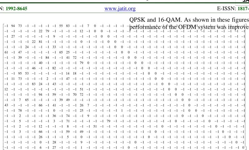
The parity-check matrix of LDPC codes used in this work is illustrated in figures 6 and 7. Figure 6 shows the parity-check matrix of the LDPC for rate 1/2. Figure 7 shows the parity-check matrix of LDPC codes for rate 1/3, which is obtained by splitting and extending the parity-check matrix of rate 1/2. In both figures, when Hmk=−1, the matrix
Right Margin 1.25
pk2
pk1
π Puncture
xk
RSC 2 RSC 1
Journal of Theoretical and Applied Information Technology 10thSeptember 2015. Vol.79. No.1
© 2005 - 2015 JATIT & LLS. All rights reserved.
ISSN:1992-8645 www.jatit.org E-ISSN:1817-3195
will be replaced by a (z × z) zero matrix; when Hmk ≥ 0, the matrix will be replaced by a circularly shifting identity matrix with Hmk. z is the expansion
[image:5.612.95.514.154.504.2]factor and is given by the z = codeword length/number of columns in the parity-check matrix.
Figure 4: Turbo code decoder Received data
SISO Decoder 1
SISO Decoder 2
π
π-1
De-multiplexer and
De-puncture ( , )C I1 ( , )C O1 (C I2, ) (C O2, )
(U I1, )
(U I2, )
(U O1, )
(U2,O)
Estimated output
Not used Not used
Figure 5: Block diagram of the proposed coded OFDM-DMWCST System P/S
S/P P/S
Output data Input data
Insert pilot symbol
S/P
Channel Compensation Mapping
AWGN
Channel Estimation Demapping
IDMWCST
DMWCST
Multipath channel LDPC/TC
Encoder
LDPC/TC Decoder
1 94 73 1 1 1 1 1 55 83 1 1 7 0 1 1 1 1 1 1 1 1 1 1
1 27 1 1 1 22 79 9 1 1 1 12 1 0 0 1 1 1 1 1 1 1 1 1
1 1 1 24 22 81 1 33 1 1 1 0 1 1 0 0 1 1 1 1 1 1 1 1
61 1 47 1 1 1 1 1 65 25 1 1 1 1 1 0 0 1 1 1 1 1 1 1
1 1 39 1 1 1 84 1 1
41 72 1 1 1 1 1 0 0 1 1 1 1 1 1
1 1 1 1 46 40 1 82 1 1 1 79 0 1 1 1 1 0 0 1 1 1 1 1
1 1 95 53 1 1 1 1 1 14 18 1 1 1 1 1 1 1 0 0 1 1 1 1
1 11 73 1 1 1 2 1 1 47 1 1 1 1 1 1 1 1 1 0 0 1 1 1
12 1 1 1 83 24 1 43 1 1 1 51 1 1 1 1 1 1
1 1 0 0 1 1
1 1 1 1 1 94 1 59 1 1 70 72 1 1 1 1 1 1 1 1 1 0 0 1
1 1 7 65 1 1 1 1 39 49 1 1 1 1 1 1 1 1 1 1 1 1 0 0
43 1 1 1 66 1 41 1 1 1 26 7 1 1 1 1 1 1 1 1 1 1 1 0
[image:5.612.93.506.546.705.2]
Journal of Theoretical and Applied Information Technology 10thSeptember 2015. Vol.79. No.1
© 2005 - 2015 JATIT & LLS. All rights reserved.
ISSN:1992-8645 www.jatit.org E-ISSN:1817-3195
5. SIMULATION AND RESULTS
[image:6.612.106.505.68.308.2]In this work, an OFDM-DMWCST system was considered to compare the BER performance of an uncoded OFDM-DMWCST system with that of the coded OFDM-DMWCST system by using LDPC codes or TCs. Three types of channels were used in the simulation, which are AWGN, Rayleigh flat fading, and Rayleigh frequency selective fading. The simulation parameters are given in Table 1. MATLAB software version 7.8 was used in the simulation. To obtain a fair comparison of the LDPC codes and TCs, we use codes of the same input word length in the comparison.
Table 1: Simulation Parameters.
Parameter Value
System bandwidth 10 MHz
Number of DMWCST points 64 Mapping type QPSK, and 16-QAM Turbo codes generator Encoder 1&2:
[1,5/7]octal, dfree=5 Number of decoding iteration 5
Code Rates 1/3, and 1/2
5.1 Performance of OFDM-DMWCST in
AWGN channel
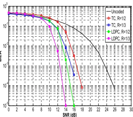
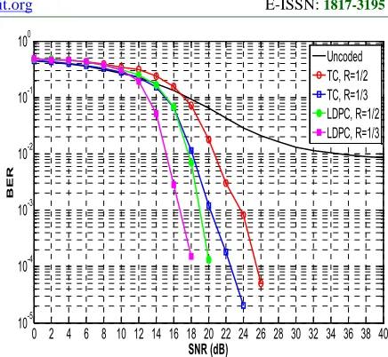
Figures 8 and 9 show the BER comparison for uncoded OFDM, LDPC-coded OFDM (LDPC-COFDM), and TC-OFDM systems over AWGN at
QPSK and 16-QAM. As shown in these figures, the performance of the OFDM system was improved by
using channel coding techniques. The BER performance of the coded OFDM system decreases by increasing the code rate. Furthermore, the performance of LDPC-COFDM was better than that of TC-OFDM.
Figure 8 shows that the LDPC-COFDM system achieves a BER of 10−3 at signal-to-noise ratio (SNR) = 4.9 and 6.8 dB for 1/3, and 1/2 code rates, respectively. The same error performance can be achieved by the TC-OFDM system at SNR = 7.4 and 8.3 dB for code rates 1/3 and 1/2, respectively. In the uncoded OFDM, the same BER is obtained at SNR = 14.1 dB.
As shown in figure 9, the LDPC-COFDM system achieves a BER of 10−3 at SNR = 9.7 and 11.2 dB for 1/3 and 1/2 code rates, respectively. The same error performance can be achieved by TC-OFDM system at SNR = 12.6 and 14.2 dB for code rates 1/3 and 1/2, respectively. In the uncoded OFDM, the same BER is obtained at SNR = 22.7 dB. 1 94 73 1 1 1 1 1 55 83 1 1 7 0 1 1
1 1 1 1 1 22 79 1 1 1 1 12 1 0 0 1 1 27 1 1 1 1 1 9 1 1 1 1 1 1 0 0 1 1 1 1 22 81 1 1 1 1 1 0 1 1 1 0 1 1 1 24 1 1 1 33 1 1 1 1 1 1 1 1 61 1 47 1 1 1 1 1 65 25 1 1 1 1 1 1
1 1 39 1 1 1 84 1
1 41 72 1 1 1 1 1 1 1 1 1 1 40 1 1 1 1 1 79 0 1 1 1 1 1 1 1 46 1 1 82 1 1 1 1 1 1 1 1 1 1 95 53 1 1 1 1 1 14 18 1 1 1 1 1 1 11 73 1 1 1 2 1 1 47 1 1 1 1 1 1 1 1 1 1 83 24 1 43 1 1 1 1 1 1 1 1 12 1 1 1 1 1 1 1 1 1 1 51 1
1 1 1
1 1 1 1 1 94 1 59 1 1 70 72 1 1 1 1 1 1 7 65 1 1 1 1 39 49 1 1 1 1 1 1 43 1 1 1 1 66 1 41
1 1 78 1 1 1 1 0 1 1 2 1 1 1 1 36 1 1 5 1 1 1 1 3 1 1 2 1 1 12 1 1 1 1 3 1 1 66 1 1 1 1 1 1 1 26 1 1 1 1 1 1 1 0 1 1 1 1 1 1 6 1
1 1 1 1 1 1 1 1 1 1 1 1 1 1 1 1 1 1 1 1 1 1 1 1 1 1 1 1 1
1 1 1 26 7 1 1 1 1 1 1 25 1 1 1 1 1 74 1 1 9 1 1 1 1 71 1 1 1 1 1 79 1 8 1 1 1 51 1 1 1 59 1 49 1 1 1 1 1 5 1 0 1 1 1 1 28 1 1 1 9 1 1 1 1 27 1 1 1 1 1 1 1 1
1 1 1 1 1 1 1 1 1 1 1 1 1 1 1 1 1 1 1 1 1 1 1 1 1 1 1 1 1 1 1 0 1 1 1 1 1 1 1 1 1 1 1 1 1 1 1 1 1 1 1 0 0 1 1 1 1 1 1 1 1 1 1 1 1 1 1 1 1 1 1 1 0 0 1 1 1 1 1 1 1 1 1 1 1 1 1 1 1 1 1 1 1 0 0 1 1 1 1 1 1 1 1 1
1 1 1 1 1 1 1
1 1 1 0 0 1 1 1 1 1 1 1 1 1 1 1 1 1 1 1 1 1 1 1 0 0 1 1 1 1 1 1 1 1 1 1 1 1 1 1 1 1 1 1 1 0 0 1 1 1 1 1 1 1 1 1 1 1 1 1 1 1 1 1 1 1 0 0 1 1 1 1 1 1 1 1 1 1 1 1 1 1 1 1 1 1 1 0 0 1 1 1 1 1 1 1 1 1
1 1
1 1 1 1 1 1 1 1 0 0 1 1 1 1 1 1 1 1 1 1 1 1 1 1 1 1 1 1 1 0 0 1 1 1 1 1 1 1 1 1 1 1 1 1 1 1 1 1 1 1 0 0 1 1 1 1 1 1 1 1 1 1 1 1 1
1 1 1 1 1 1 1 1 1 1 1 1 1 1 1 1 1 1 1 1 1 1 1 1 1 1 1 1 1 1 1 1 0 1 1 0 1
1 1 1 1 1 1 0 1 1 1 1 1 1 1 1 1 1 1 1 1 1 0 0 1 1 1 1 1 1 1 1 1 1 1 1 0 1 1 0 1 1 1 1 1 1 1 0 1 1 1 1 0 1 1 0 1 1 1 1 1 1 1 1 0 1 1 1 1 1 1 1 1 1 0 1 1 1 1 1 1 1 1 1 1 1 1 1 1 1 1 1 1 1 1 1 1 1 1 1 1 1 1 1 1 1
1 1 1 1 1 1 1 1 0 1 1 1 1 1 0 1 1 1 1 1 0 1 1 1 1 1 0 1 1 1 1 1 0
[image:6.612.88.300.536.626.2]
Journal of Theoretical and Applied Information Technology 10thSeptember 2015. Vol.79. No.1
© 2005 - 2015 JATIT & LLS. All rights reserved.
ISSN:1992-8645 www.jatit.org E-ISSN:1817-3195
0 2 4 6 8 10 12 14 16 18
10-5 10-4 10-3 10-2 10-1 100
SNR (dB)
B
E
R
Uncoded TC, R=1/2 TC, R=1/3 LDPC, R=1/2 LDPC, R=1/3
0 2 4 6 8 10 12 14 16 18 20 22 24 26 10-5
10-4 10-3 10-2 10-1 100
SNR (dB)
B
E
R
Uncoded TC, R=1/2 TC, R=1/3 LDPC, R=1/2 LDPC, R=1/3
0 2 4 6 8 10 12 14 16 18 20 22 24 26
10-5 10-4 10-3 10-2 10-1 100
SNR (dB)
B
E
R
Uncoded TC, R=1/2 TC, R=1/3 LDPC, R=1/2 LDPC, R=1/3
0 2 4 6 8 10 12 14 16 18 20 22 24 26 28 30 10-5
10-4 10-3 10-2 10-1 100
SNR (dB)
B
E
R
[image:7.612.82.531.65.557.2]Uncoded TC, R=1/2 TC, R=1/3 LDPC, R=1/2 LDPC, R=1/3 Figure 8: Performance of coded OFDM-DMWCST in
AWGN at QPSK
Figure 9: Performance of coded OFDM-DMWCST in AWGN at 16-QAM
5.2 Performance of OFDM-DMWCST in flat fading channel
Figures 10 and 11 show the BER comparison for uncoded OFDM, LDPC-COFDM, and TC-OFDM over the Rayleigh flat fading channel for QPSK and 16-QAM.
As shown in figure 10, the performance of the LDPC codes is slightly better than that of the TCs in terms of achievable BER.
Figure 11 illustrates that the LDPC-COFDM system has a better performance than the TC-OFDM system. The LDPC-CTC-OFDM has a BER performance 10−3 at SNR = 12.5 and 14.2 dB for 1/3 and 1/2 code rates, respectively. The same error performance can be achieved by TC-OFDM system
[image:7.612.311.527.100.328.2]at SNR = 15.2 and 16.6 dB for code rates 1/3 and 1/2, respectively. In the uncoded OFDM, the same BER is obtained at SNR = 23.5 dB.
Figure 10: Performance of coded OFDM-DMWCST in flat fading channel at QPSK
Figure 11: Performance of coded OFDM-DMWCST in flat fading channel at 16-QAM
5.3 Performance of OFDM-DMWCST in
frequency-selective fading channel
Figures 12 and 13 show the BER comparison for uncoded OFDM, LDPC-COFDM, and TC-OFDM over the Rayleigh frequency-selective fading channel for QPSK and 16-QAM. Two paths were selected. The second path had a gain of (−10) dB
[image:7.612.313.526.364.551.2]Journal of Theoretical and Applied Information Technology 10thSeptember 2015. Vol.79. No.1
© 2005 - 2015 JATIT & LLS. All rights reserved.
ISSN:1992-8645 www.jatit.org E-ISSN:1817-3195
0 2 4 6 8 10 12 14 16 18 20 22 24 26 10-5
10-4 10-3 10-2 10-1 100
SNR (dB)
B
E
R
Uncoded TC, R=1/2 TC, R=1/3 LDPC, R=1/2 LDPC, R=1/3
0 2 4 6 8 10 12 14 16 18 20 22 24 26 28 30 32 34 36 38 40 10-5
10-4 10-3 10-2 10-1 100
SNR (dB)
B
E
R
Uncoded TC, R=1/2 TC, R=1/3 LDPC, R=1/2 LDPC, R=1/3 channel than the uncoded OFDM. Moreover,
LDPC-COFDM was better than TC-OFDM.
As shown in figure 12, the LDPC-COFDM has almost the same BER performance as the TC-OFDM in terms of the achievable BER. The coded OFDM system provides a coding gain of 8 dB for the 1/3 code rate and 7 dB for the 1/2 code rate over the uncoded OFDM system.
[image:8.612.305.523.79.280.2]Figure. 13 shows that the BER became constant at 8.6 × 10⁻³at an SNR of approximately 36 dB in the uncoded OFDM because no CP existed in the case of the OFDM-DMWCST system. Hence, ISI occurred and resulted in the loss of orthogonality between subcarriers. Error-correcting codes can eliminate the residual ISI, thus offering better performance in this channel. Furthermore, the performance of OFDM-DMWCST with the LDPC coding scheme was better than that with the turbo-coding scheme. As shown in this figure, the LDPC-COFDM system had a BER of 10−2 at SNR = 15 and 17.7 dB for code rates 1/3 and 1/2, respectively. TC-OFDM had the same BER at SNR = 18 and 20.6 dB for code rates 1/3 and 1/2, respectively. Furthermore, the uncoded OFDM had the same BER at SNR = 34 dB.
[image:8.612.87.301.411.592.2]Figure 12: Performance of coded OFDM-DMWCST in selective fading channel at QPSK
Figure 13: Performance of coded OFDM-DMWCST in selective fading channel at 16-QAM
6. CONCLUSION
In this work, LDPC codes and TCs are proposed for the OFDM-DMWCST system to achieve higher performance and robustness against wireless communication channel. The performance analysis of the proposed systems was evaluated by simulations in different channels, including AWGN, Rayleigh flat fading, and Rayleigh frequency selective fading. The simulation results indicated that the use of channel coding with the OFDM-DMWCST system can eliminate the residual ISI, therefore, offering a higher data rate in wireless mobile communications. Also, the improvement in the BER performance of the coded OFDM system increases by decreasing the code rate. In addition, the LDPC codes give better BER performance than the turbo codes in all types of the channels used in this work.
REFERENCES:
[1] A. Goel and M. K. Garg, “Comparative
performance evaluation of convolutionally coded and LDPC coded OFDM system over AWGN and SUI-5 fading channel,” in Proceeding of IEEE International Conference on Computer and Communication Technology, 2012, pp. 250-254.
[2] R. V. Nee and R. Prasad, OFDM for wireless multimedia communications: Artech House, Inc., 2000.
[3] M. A. Saeed, B. M. Ali, and M. H. Habaebi,
Journal of Theoretical and Applied Information Technology 10thSeptember 2015. Vol.79. No.1
© 2005 - 2015 JATIT & LLS. All rights reserved.
ISSN:1992-8645 www.jatit.org E-ISSN:1817-3195
[4] M. Oltean, “Wavelet OFDM performance in flat fading channels,” Scientific Bulletin of University Politehnica Timisoara, ETC Series, vol. 52, 2007, pp. 167-172.
[5] S. K. Borra and S. K. Chaparala, “Performance
evaluation of OFDM system with Rayleigh,
Rician and AWGN channels,” International Journal of Emerging Technology and Advanced Engineering, vol. 3, 2013.
[6] A.R. Lindsey, “Wavelet packet modulation for
orthogonally multiplexed communication,” IEEE Trans. in Signal Processing, vol. 45, 1997, pp. 1336–1337.
[7] B. G. Negash and H. Nikookar, “Wavelet based OFDM for wireless channels,” in Proceedings of IEEE International Conference on Vehicular Technology, vol. 1, 2001, pp. 688-691.
[8] K. Abdullah and Z. M. Hussain, “Performance
of Fourier-based and wavelet-based OFDM for DVB-T systems,”in Proceedings of Conference on Telecommunication Networks and Applications, pp. 475-479, Australasian, 2007. [9] V. Strela, P. N. Heller, G. Strang, P. Topiwala,
and C. Heil, “The application of multiwavelet filter banks to image processing,” IEEE Trans. on Image Processing, vol. 8, 1999, pp. 548-563. [10] D. Milovanovic, A. Marincic, G. Petrovic, and
Z. Barbaric, “Comparative study of scalar and multiwavelet filters in transform-based
compression of IRLS images,” in Proceedings of Conference on Telecommunications in Modern Satellite, Cable and Broadcasting Services, 1999, pp. 169-172.
[11]M. B. Martin and A. E. Bell, “New image compression techniques using multiwavelets
and multiwavelet packets,” IEEE Trans. on Image Processing, vol. 10, 2001, pp. 500-510. [12] S. A. Dawood, F. Malek, M. S. Anuar, and S.
Q. Hadi, “Discrete multiwavelet critical-sampling transform-based OFDM system over Rayleigh fading channels,” Journal of Mathematical Problems in Engineering, vol. 2015(676217), 1-10, 2015.
[13] P. G. Farrell, Essentials of error-control coding: John Wiley & Sons, 2006.
[14] C. Berrou , A. Glavieux, and P. Thitimajshima,
“Near Shannon limit error-correcting coding and decoding: turbo-codes,” in Proceedings of ICC'93, Geneva, Switzerland, 1993, pp. 1064-1070.
[15] H. Nikopour, A. K. Khandani, and S. H. Jamali, "Turbo-coded OFDM transmission over a nonlinear channel," Vehicular Technology,
IEEE Transactions on, vol. 54, 2005, pp. 1361-1371.
[16] H. Savitha and M. Kulkarni, "Performance evaluation of Turbo coded OFDM systems and application of Turbo decoding for impulsive channel," ICTACT International Journal on Communication Technology, vol. 1, 2010, pp. 175-183.
[17] M. N. Sharma and R. L. Dua, "To improve bit error rate of OFDM transmission using turbo codes," International Journal of Advanced Research in Computer Engineering & Technology (IJARCET), vol. 1, 2012, pp. 37-44. [18] R. G. Gallager, “Low density parity check codes,” IRE Trans.Inform. Theory, vol. IT - 8, 1962, pp. 21 - 28.
[19]D. J. C. MacKay and R. M. Neal, “Near
Shannon limit performance of low density
parity check codes,” Electron. Lett., vol.32, no. 18, 1996, pp. 1645 - 1646.
[20] H. Futaki and T. Ohtsuki, "Low-density parity-check (LDPC) coded OFDM systems," in Vehicular Technology Conference, 2001. VTC 2001 Fall. IEEE VTS 54th, 2001, pp. 82-86. [21] H. Zhang and D. Yuan, "Performance research
between turbo and LDPC coded WOFDM on Rayleigh Fading Channels," Shangdong University White papers, 2004.
[22] M. S. Anwar, M. Zeeshan, S. Aslam, M. A. Ajaz, and M. Salman, "Comparative performance evaluation of LDPC coded and turbo coded OFDM systems in SUI multipath channel models," International Conference on Computer Applications and Industrial Electronics (ICCAIE), 2010.
[23] S. Singh, N. Sood, and A. Sharma, "Performance evaluation of LDPC and turbo coded OFDM System in Nakagami-M Fading," International Journal of Computer Theory & Engineering, vol. 4, 2012.
[24] T. Ta, "A Tutorial on Low Density Parity-Check Codes," The University of Texas at Austrin.
[25] H. Futaki and T. Ohtsuki, "Low-density parity-check (LDPC) coded OFDM systems with M-PSK," in Vehicular Technology Conference, (VTC), IEEE 55th, 2002, pp. 1035-1039. [26] S. Benedetto, D. Divsalar, G. Montorsi, and F.
Pollara, “A soft-input soft-output maximum a posteriori (MAP) module to decode parallel and