Transient and Load Flow Analysis of an IEEE 13
Bus System with Wind Farm Integration
Greeshma Sara1, Ramakrishna K2
1, 2
B V Raju Institute of Technology
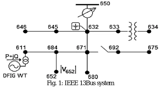
Abstract: In this paper we present an IEEE 13 Bus outspread dispersion framework with wind cultivate associated at the feeble transport. The breeze cultivate utilized is a DFIG (Doubly Fed Induction Generator) twist cultivate with 1.5MW age. A load flow investigation is completed at each transport utilizing Newton Rapson technique. The voltage adjustment with stack sharing at various transports is contemplated. Symmetrical and Unsymmetrical issues are presented and a transient examination is done. The strength of the voltage regarding the blame conditions is investigated. The displaying and examination is completed in MATLAB Simulink condition with every single graphical portrayal.
I. INTRODUCTION
Doubly fed induction generator (DFIG)- based breeze age is an appealing choice for reasonable vitality reconciliation in microgrids. In small scale frameworks with significant wind vitality infiltration, wind speed varieties mean fluctuations in electrical factors and contributes towards control quality issues [2], [3], for example, varieties in transport voltages [4], [5]. As noted in IEEE 1547, such fluctuations can disturb the ordinary operation of voltage direction gadgets; along these lines, the coupling of a controllable responsive power source with the breeze vitality framework is proposed to flatten out the voltage varieties [6]. Since coordinate voltage control by wind vitality frameworks may meddle with other voltage direction gadgets, it is disallowed by IEEE 1547. An appropriate technique for responsive power administration of DFIG wind frameworks in light of the voltage affectability examination is proposed in [7]. The technique disposes of the potential for impedance with other voltage direction gadgets by locally altering the DFIG receptive power in light of voltage affectability investigation. In any case, the strategy in [7] depends on the traditional control and performed by the decoupled PI rotor current control circles. Subsequently the control execution is profoundly reliant on PI controller parameters and DFIG parameters [8], which are liable to unavoidable mistakes.
Since wrong parameters debase control execution, coordinate torque control (DTC) and direct power control(DPC) techniques in view of the sliding mode control (SMC) have been proposed as suitable choices [9], [10]. Reference [11] presents a DTC technique in view of the estimation of rotor flux position, and [8] uses assessed stator fluxtoavoid difficulties related with the rotor flux estimation. SMC-based DTC strategies are proposed in [12] while uncommon thought is spent on the breeze turbine mechanical anxiety. The strategy proposed by [12] enhances the breeze framework unwavering quality, and the technique in administers the breeze turbine in various operation districts. Reference accomplishes steady exchanging recurrence for the SMC-based DPC. In a SMC procedure is considered which incorporates consistent and broken parts and ensures the most extreme power point following (MPPT) and minimum copper misfortunes of a doubly encouraged hesitance generator. Reference proposes a high request SMC-based DTC for marine DFIG wind turbines and [10] dispenses with the need of rotor speed adaption in the DTC techniques by utilizing a sliding mode onlooker.
Fig. 1: IEEE 13Bus system
II. LOAD FLOW ANALYSIS OF IEEE 13 BUS SYSTEM
Load flow analysis is the most critical and basic way to deal with researching issues in control framework working and arranging. In light of a predefined creating state and transmission organize structure, stack stream investigation illuminates the enduring operation state with hub voltages and branch control stream in the power framework. Load stream investigation can give an adjusted unfaltering operation condition of the power framework, without considering framework transient procedures. Subsequently, the mathematic model of load stream issue is a nonlinear logarithmic condition framework without differential conditions. Power framework dynamic investigation researches framework soundness under some given aggravations. Its mathematic show incorporates differential conditions. It ought to be called attention to that unique examination depends on stack stream investigation and the calculation of load stream investigation is additionally the base for dynamic examination techniques. Along these lines, recognition with the hypothesis and calculations of load stream examination is basic to understanding the philosophy of present day control framework investigation. The below is the load flow analysis of IEEE 13Bus system with DFIG wind farm at end bus. In MATLAB we use Newton Rapson method for Load flow analysis from Power GUI environment.
The Load Flow converged in 0 iterations !
SUMMARY for sub network No 1 Total generation : P= 2.36 MW Q= 1.64 Mvar Total PQ load : P= -0.00 MW Q= 0.01 Mvar Total Zshuntload : P= 2.36 MW Q= 1.59 Mvar Total ASM load : P= 0.00 MW Q= 0.00 Mvar Total losses : P= 0.00 MW Q= 0.04 Mvar
A. BUS_1 V= 1.000 pu/132kV 0.00 deg ; Swing bus Generation : P= 2.36 MW Q= 1.64 Mvar
PQ_load : P= 0.00 MW Q= 0.00 Mvar Z_shunt : P= 0.00 MW Q= 0.00 Mvar --> BUS_4 : P= 2.35 MW Q= 1.63 Mvar
B. BUS_10 V= 0.993 pu/11kV 29.57 deg Generation : P= 0.00 MW Q= 0.00 Mvar PQ_load : P= -0.00 MW Q= -0.00 Mvar Z_shunt : P= 0.17 MW Q= 0.15 Mvar --> BUS_11 : P= 0.08 MW Q= 0.05 Mvar --> BUS_9 : P= -0.25 MW Q= -0.20 Mvar
D. BUS_12 V= 0.993 pu/11kV 29.57 deg Generation : P= 0.00 MW Q= 0.00 Mvar PQ_load : P= -0.00 MW Q= 0.00 Mvar Z_shunt : P= 0.12 MW Q= 0.08 Mvar --> BUS_8 : P= -0.12 MW Q= -0.08 Mvar
E. BUS_13 V= 0.993 pu/11kV 29.57 deg Generation : P= 0.00 MW Q= 0.00 Mvar PQ_load : P= 0.00 MW Q= 0.00 Mvar Z_shunt : P= 1.24 MW Q= 0.71 Mvar --> BUS_9 : P= -1.24 MW Q= -0.71 Mvar
F. BUS_2 V= 0.994 pu/11kV 29.58 deg Generation : P= 0.00 MW Q= 0.00 Mvar PQ_load : P= 0.00 MW Q= 0.00 Mvar Z_shunt : P= 0.08 MW Q= 0.14 Mvar --> BUS_3 : P= -0.08 MW Q= -0.14 Mvar
G. BUS_3 V= 0.994 pu/11kV 29.58 deg Generation : P= 0.00 MW Q= 0.00 Mvar PQ_load : P= -0.00 MW Q= -0.00 Mvar Z_shunt : P= 0.17 MW Q= 0.12 Mvar --> BUS_2 : P= 0.08 MW Q= 0.14 Mvar --> BUS_4 : P= -0.25 MW Q= -0.26 Mvar
H. BUS_4 V= 0.995 pu/11kV 29.57 deg Generation : P= 0.00 MW Q= 0.00 Mvar PQ_load : P= -0.00 MW Q= 0.01 Mvar Z_shunt : P= 0.10 MW Q= 0.06 Mvar --> BUS_1 : P= -2.35 MW Q= -1.61 Mvar --> BUS_3 : P= 0.25 MW Q= 0.26 Mvar --> BUS_5 : P= 0.39 MW Q= 0.29 Mvar --> BUS_9 : P= 1.62 MW Q= 0.99 Mvar
I. BUS_5 V= 0.994 pu/11kV 29.57 deg Generation : P= 0.00 MW Q= 0.00 Mvar PQ_load : P= 0.00 MW Q= 0.00 Mvar Z_shunt : P= 0.00 MW Q= 0.00 Mvar --> BUS_4 : P= -0.39 MW Q= -0.29 Mvar --> BUS_6 : P= 0.39 MW Q= 0.29 Mvar
J. BUS_6 V= 0.985 pu/6.6kV 28.86 deg Generation : P= 0.00 MW Q= 0.00 Mvar PQ_load : P= 0.00 MW Q= -0.00 Mvar Z_shunt : P= 0.39 MW Q= 0.28 Mvar --> BUS_5 : P= -0.39 MW Q= -0.28 Mvar
--> *1* : P= 0.00 MW Q= 0.00 Mvar --> BUS_8 : P= -0.00 MW Q= -0.00 Mvar
L. BUS_8 V= 0.993 pu/11kV 29.57 deg Generation : P= 0.00 MW Q= 0.00 Mvar PQ_load : P= -0.00 MW Q= 0.00 Mvar Z_shunt : P= -0.00 MW Q= 0.00 Mvar --> BUS_12 : P= 0.12 MW Q= 0.08 Mvar --> BUS_7 : P= 0.00 MW Q= 0.00 Mvar --> BUS_9 : P= -0.13 MW Q= -0.08 Mvar
M. BUS_9 V= 0.993 pu/11kV 29.56 deg Generation : P= 0.00 MW Q= 0.00 Mvar PQ_load : P= 0.00 MW Q= 0.00 Mvar Z_shunt : P= -0.00 MW Q= -0.00 Mvar --> BUS_10 : P= 0.25 MW Q= 0.20 Mvar --> BUS_13 : P= 1.24 MW Q= 0.71 Mvar --> BUS_4 : P= -1.62 MW Q= -0.99 Mvar --> BUS_8 : P= 0.13 MW Q= 0.08 Mvar
Scientifically, the load flow issue is an issue of tackling an arrangement of nonlinear arithmetical conditions. Its answer typically can't keep away from some cycle procedure. Hence solid merging turns into the prime paradigm for a load flow estimation technique. With the size of energy framework consistently extending, the measurement of load flow conditions now turns out to be high (a few thousands to several thousands). For the conditions with such high measurements, we can't guarantee that any numerical strategy can unite to a right arrangement. This circumstance requires the specialists and researchers in the power framework investigation field to look for more solid techniques.
III. TRANSIENT ANALYSIS
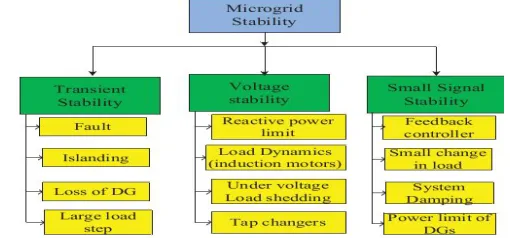
A microgrid is spoken to as a blend of various circulated vitality assets and different loads. Solidness issues emerging in microgrid are fundamentally the same as those emerging in expansive power framework viz transient strength, voltage dependability and little flag steadiness [2]. The regular reasons of these dependability issues are given in Fig. 1.
In this paper the principle concentrate is on transient dependability of microgrid. Transient dependability of a microgrid can be characterized as its capacity to recover its steady operation after an expansive aggravation. Micro sources have a next to no turning save and receptive backings so it is critical to play out an itemized transient strength investigation of a microgrid. Blame delivers a transient soundness issue in microgrid and it is fundamental to disengage the defective part from the solid part. On the off chance that the blame is in utility grid, the entire microgrid framework experiences voltage and recurrence crumple [3].
[image:5.612.180.435.601.720.2]To avoid microgrid fall because of a blame in utility grid it is important to disconnect the microgrid, If there is lost age or any generator isn't in benefit like WTG because of inaccessibility of twist, on the other hand load shedding is required unless any capacity or battery is accessible to sustain every one of the loads. A sudden excursion of load may likewise prompt transient unsteadiness. Capacity gadgets can give a superior answer for this issue.
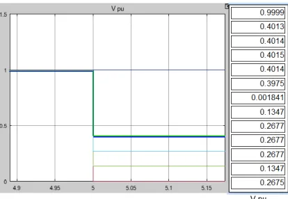
Fig. 3: Voltages of 13buses in fault condition
III. CONCLUSION
With the above results of Load flow analysis and transient analysis of the IEEE 14 bus system it can be ensured that the bus system is stable. All the bus power exchange values are noted with the help of Load flow Newton rapson method. In transient analysis the bus voltages are noted with fault introduced at one of the bus.
REFERENCES
[1] F. Katiraei, R. Iravani, N. Hatziargyriou, and A. Dimeas, “Microgrids management,” IEEE Power Energy Mag., vol. 6, no. 3, pp. 54–65, May/ Jun. 2008. [2] T.Sun,Z. Chen, andF. Blaabjerg,“Flicker study on variable speed wind turbines with doubly fed induction generators,” IEEE Trans. Energy Convers., vol. 20,
no. 4, pp. 896–905, Dec. 2005
[3] Y. S. Kim and D. J. Won, “Mitigation of the flicker level of a DFIG using power factor angle control,” IEEE Trans. Power Del.,vol.24, no. 4, pp. 2457–2458, Oct. 2009.
[4] T. Thiringer, “Frequency scanning for power system property determination—Applied to a wind power grid,” IEEE Trans. Power Syst., vol. 21, no. 2, pp. 702– 708, May 2006.
[5] A. Larsson, “Flicker emission of wind turbines during continuous operation,” IEEE Trans. Energy Convers., vol. 17, no. 1, pp. 114–118, Mar. 2002. [6] Standard for Interconnecting Distributed Resources With Electric Power Systems, IEEE 1547-2-2008, Dec. 2008.
[7] R. Aghatehrani and R. Kavasseri, “Reactive power management of a DFIG wind system in microgrids based on voltage sensitivity analysis,” IEEE Trans. Sustain. Energy, vol. 2, no. 4, pp. 451–458, Oct. 2011.
[8] L. Xu and P. Cartwright, “Direct active and reactive power control of DFIG for wind energy generation,” IEEE Tran. Energy Convers., vol. 21, no. 3, pp. 750– 758, Sep. 2006.
[9] S. Z. Chen, N. C. Cheung, K. C. Woong, and J. Wu, “Integral sliding-mode direct torque control of doubly-fed induction generators under unbalanced grid voltage,” IEEE Trans. Energy Convers., vol. 25, no. 2, pp. 356–367, Jun. 2010.
[10] C. Lascu, I. Boldea, and F. Blaabjerg, “Very low speed variable structure control of sensorless induction machine drives without signal injection,” IEEE Trans. Ind. Electron., vol. 41, no. 2, pp. 591–598, Mar. 2005.
[11] K. P. Gokhale, D. W. Karraker, and S. J. Heikkila, “Controller for a Wound Rotor Slip Ring Induction Machine,” U.S. Patent 6448735B1, Sep. 2002