Railway Fault Detection System using Mobile
Communication and Sensor Technology
Mr. P . Madhusudhan Reddy1, Mr. I. Sharath Chandra2,Prof. B. Kedarnath3
1,2
Assistant Professor, 3Professor &HOD-ECE Department of Electronics and Communication Engineering, Guru Nanak Institute of Technology, Hyderabad, Telangana, India-501506
Abstract: This paper proposes a cost effective yet robust solution to the problem of railway crack detection, obstacle detection and fire detection utilizing a method that is unique in the sense that while it is simple, the idea is completely novel and hit her to untested. This project helps in safe guarding the railway property.ARM 9 processor is the heart of this project.ARM 9 is embedded with two motors. Of them one motor functions as train brake system and other is used for water flushing whenever a fire sensor gets activated. An ultra sonic sensor is provided to detect the obstacles on the track. A LDR sensor is provided to detect the track damage. A LCD display is used to display the type of defect occurred during train‘s journey. The proposed scheme has been modeled for robust implementation in the Indian scenario
Keywords: crack detection, obstacle detection, fire detection,ARM9 Processor, LDR Sensor.
I. INTRODUCTION
Many systems have been come into existence to avoid train accidents. The existing system is a single task module. It is manual watching system. The percentage of accuracy is very less in this case and drivers may not be alert all the time. Even if the person is alert, it takes time to stop the train manually. There is delay in time, operating the existing system.
Multiple functionality system is provided in this paper. Firstly, track damage status is monitored by the sensor and wireless modules, when the sensor not getting signal, immediately notifies and alert or informs to the current train or authority people on the track. The above task can be achieved through microcontrollers, GSM and GPS, sensors.
Secondly, an ultrasonic sensor is provided to detect the obstacles which comes in between the path of the train’s journey. It detects the object and automatically applies the brakes and avoids the train accident.
Finally fire sensor is provided to detect the fire. As soon as the fire sensor gets activated, alarm produces and a water flushing system gets activated. Simultaneously display is made available on LCD screen about box on fire and brakes are activated automatically.
A. Literature Survey
Power Supply A R M 9
LDR Sensor LDR Sensor
LED LED Motor Unit-1 Motor Unit-2 Ultrasonic sensor Alert section GSM GPS U A R T
Fire Sensor A Relay /Device
D C
Fig.1.Block diagram of railway safety system
II. OPERATION
Active motor1
Activate
Display on LCD fire detection
Start
Train monitoring
defe
Blow the
Deactivate
Deactivate
Display obstacle Deactivate
Display track
DEFECT???
III. ALGORITHM
no yes
FIRE detection TRACK detection OBSTACLE detection
Fig.3. Flow chart for the operation of railway safety system
Fig.4. Overview of the railway safety system
Fire sensor is used for detecting the fire when ever fire breaks out in the train and blow the buzzer.
When there is no smoke the light from the bulb will be directly falling on the LDR. The LDR resistance will be low and so the voltage across it (below 0.6V). The transistor will be OFF and nothing happens. When there is sufficient smoke to mask the light from falling on LDR, the LDR resistance increases and so do the voltage across it. Now the transistor will switch to ON.
Fig .6: Message of position of train to base station when fire is detected
[image:5.612.237.377.262.385.2]This entire figure illustrates controller detection of section fire and water flushing system is providing using motors. When the fire detects the buzzer blows and motor 1stops and motor 2 starts running
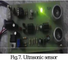
Fig.7. Ultrasonic sensor
This sensor is detecting the obstacles whichever comes in between the path of the train.
Fig .8.Message of position of trim to base station when object is detected
[image:5.612.226.387.411.473.2]The above figure illustrates controller detection of section obstacle is provide using motors. When the obstacle detects motor 1 stops running. This is to for checking whether there is any obstacle in the path of train.
Fig.11. LCD displaying track damage detected
Fig.12. Message of position of train to base station when track damage detected
This entire figure illustrates controller detection section of track damage is provide. When the track damage the motor 1 stops running. This is to for checking track damage in the path of train.
IV. ADVANTAGES AND DISADVANTAGES
A. Advantages
1) The sensors sense the input and sends to the microcontroller, where it responds and gives command to the particular component with predefined algorithm.
2) The time parameters are crucial which can be easily changed and modified using Micro-controllers.
3) Thus, this device would work in coherence would help to reduce the train collisions.
4) Reduce the death ratio during the fire accidents to provide help fastly.
B. Disadvantages
1) High Complexity: Since there are three different sections connected to single system the software program to switch from one mode to another through interrupts becomes difficult. The hardware complexity is also very large which further increases maintenance and upgrade cost.
V. CONCLUSION
In this project, an anti-collision system for trains have been designed, simulated and tested. The simulation has been done using protest electronic simulation package Train collisions, de railing & rail road accidents are avoided. Hence it is expected that, major train mishaps can be prevented and human life can be saved if this system is implemented.
It also helps in preventing the major loss to Indian railways system by providing fire detection system. Flushing of water stops the fire expanding to its adjacent boxes and alerts the passengers with its buzzer system.
It also provides the obstacle detection which helps reducing the suicide cases and protecting the wild life.
VI. FUTURE SCOPE
and at level-crossing gates, thereby saving the lives of rail passengers and road users. This device can be integrated with the Anti Collision Device for better sophistication and optimization
REFERENCES
[1] S. Ramesh,”Detection of Cracks and Railway Collision Avoidance System”, International Journal of Electronic and Electrical Engineering ISSN 0974-2174 Volume 4, Number 3 (2011), pp. 321-327
[2] Molla Shahadat Hossain Lipu, Md. Lushanur Rahman, Tahia Fahrin Karim, Faria Sultana, “Wireless Security Control System & Sensor Network for Smoke & Fire Detection” , 2010 IEEE.
[3] A.D. Putorti Jr and J. McElroy Full-Scale House Fire Experiment for InterFIRE VR, Report of Test, , November 2, 1999, Revised April 10, 2000. [4] Davis, C. L., RSSB Report, Modelling and detecting damage (wear and RCF) in rails, University of Birmingham, May 2008.
[5] Bentley, M. N., Lund, F. P., Withers, A., Field Gradient Imaging technology, applications and solutions for component and structural integrity for track and rolling stock for the rail industry, NEWT International Limited, NSP1001, 26/04/04.
[6] Collision Avoidance Systems www.collision-avoidance.org [7] Vibration Sensors www.vibrametrics.com; www.ni.com [8] Raksha Kavach Anti Collision Devices. www.konkanrailway.com