© 2017, IRJET | Impact Factor value: 5.181 | ISO 9001:2008 Certified Journal
| Page 3330
Design and analysis of Microstrip Patch Antenna for Lung Tumor
J. Mary Sushmitha Asha
1, Dr. K. Madhan Kumar
21
PG Scholar, Department of Electronics and Communication Engineering, PET Engineering College, Tamil Nadu,
India
2
Professor, Department of Electronics and Communication Engineering, PET Engineering College, Tamil Nadu,
India
---***---
Abstract -
Cancer is a serious health problem amongvarious kinds of diseases. More than one in three people will be affected by some form of cancer during their lifetime. Among various types of cancer, Lung cancer is a leading cause of cancer-related death in many countries. In this paper, we have design a lung Tumor which consist of a microstrip patch antenna ,Lung Model and Tumor in CST. This shows that the Tumor present in the lung can be detected by observing the current density of Lung with and Without Tumor. The variations in E-field, H-field, Current density are measured. It is found that the current density value has been increased twice than that of the brain without tumor , E-field And Magnetic Field value get reduced in the presence of Tumor.
Key Words:
Fractal, Microstrip Patch antenna, Lung Phantom
1. INTRODUCTION
Bio Medical Images give information of shape and function of organs of human body, being one of the most important mean for establishing the diagnosis. Cancer is a group of diseases characterized by the uncontrolled development and spread of unusual cells. If the spread is not controlled, it can bring about death.[1] Lung cancer occurred in 1.8 million people and resulted in 1.6 million deaths. Lung Cancer happens on account of unwanted development in the tissue of the lung. The abnormal cells do not develop into healthy lung tissue, they divide rapidly and form tumors. The growth that unfolding on the far side of the respiratory organ in an exceeding method called metastasis and additionally spread into alternative elements of the body.[2]Most cancers that begin its growth in lung is known as carcinomas. The two main types are Non-Small cell Lung Carcinoma and Small Cell lung carcinoma. Small cell lung carcinoma is also sometimes called small cell undifferentiated Carcinoma. Carcinoma is a generic term referring to any malignant tumor that comes from epithelial cells. Small cell lung Carcinoma grows Quickly. Non-Small cell lung Carcinoma grows slowly. Basic methods like Positron Emission Tomography
(PET), Computed Tomography (CT) and Biopsy are used to detect the tumor. [3]Positron Emission Tomography and computed Tomography are able to define the level of diseases both anatomically and functionally. The overwhelming majority (85%) of cases of carcinoma are because of long tobacco smoking regarding 10-15% of cases occur in folks that have not smoke-dried.
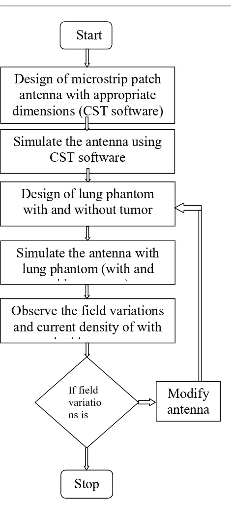
In this paper, a Fractal based micro strip antenna for Lung tumor detection is proposed. This proposed antenna is designed and simulated over computer simulation technology (CST) microwave studio (MWS), which is based on finite integration technique. The proposed antenna is simulated upon Lung phantom with and without tumor separately and the variations in current density, E-Field and H-field in the presence of tumor shows the efficient performance of antenna is shown in Fig-1.
2. PROPOSED METHOD
2.1 Antenna design
© 2017, IRJET | Impact Factor value: 5.181 | ISO 9001:2008 Certified Journal
| Page 3331
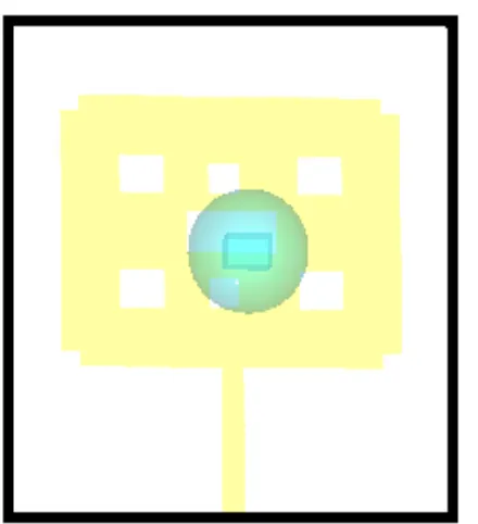
2.2 Lung phantom design
A lung phantom is designed by considering a cube as lung and a sphere as a tumor. The permittivity of the lung is 2 and its conductivity is 1.3S/m. A cube with dimensions 6 x 4 x 5 mm3 is considered as a tumor with permittivity 54.2 and conductivity 2.62 S/m. Tumors will have very high conductivity and different dielectric properties than healthy tissues.
In this proposed work, first the antenna is designed and simulated over computer simulation technique. Next the lung phantom is designed with appropriate
dimensions using computer simulation technique. Then the proposed antenna is simulated upon lung phantom with and without tumor separately and it is found that the current density and specific absorption rate has been drastically increased in the presence of tumor within the Lung.
[image:2.595.308.543.82.594.2].
Fig -1: Steps involved in proposed work
Design of microstrip patch
antenna with appropriate
dimensions (CST software)
Design of lung phantom
with and without tumor
Simulate the antenna with
lung phantom (with and
without tumor)
Simulate the antenna using
CST software
Observe the field variations
and current density of with
and without tumor
If field
variatio
ns is
enough
Stop
Start
© 2017, IRJET | Impact Factor value: 5.181 | ISO 9001:2008 Certified Journal
| Page 3332
Fig -2: Structure of Proposed AntennaTable -1: Antenna Design Specifications
Parameter Descriptions Value
Ls Length of the substrate 65 Ws Width of the substrate 60 Wp Width of the patch 45.64 Lp Length of the patch 35.44
L Length of 1st slot 2 W Width of 1st slot 2.5 L Length of 2nd,3rd,4th,5th slot 10 W Width of 2nd,3rd,4th,5th slot 12 L Length of 6th,7th slot 5 W Width of 6th,7th slot 6
3. SLOTS SPECIFICATIONS
The patch is loaded with seven slots. The length of each is 65mm and the width of each slots is 60mm.The Length of the first, second, third and fourth slots is 10mm and the width of the first, second ,third ,fourth slots is 12mm.The Length of the fifth, sixth and seventh slots is 5mm and the width of the fifth, sixth, seventh slots is 6mm.
The Return loss can be calculated by, RL=10 log(Pout/Pin) Current Density can be calculated by,
J=I / A
Electric Field can be calculated by, E=k*q/d2
4. RESULTS AND DISCUSSION
The performance of the proposed antenna is found by simulating the antenna with computer simulation technology (CST) microwave studio which is based on finite integration technique . The proposed antenna is kept at a distance of 15 mm from the lung phantom and simulated over CST for lung tumor detection.
Fig -4: Simulated return loss (S11) curve versus frequency of proposed antenna
Fig-4 shows the return loss (S11) curve of the designed antenna obtained by CST simulator. The proposed antenna resonates at three different frequencies and here 5.02 GHz alone is considered for brain tumor detection.
Fig -4: Electric Field at 5.0 GHz-with tumor
[image:3.595.44.284.393.544.2] [image:3.595.309.556.456.567.2]© 2017, IRJET | Impact Factor value: 5.181 | ISO 9001:2008 Certified Journal
| Page 3333
Fig -5: Magnetic Field at 5.0 GHz-with tumorFrom the above figure, it was observed that the antenna has a Magnetic Field of 106A/m at 5.0GHz in the presence of Tumor.
Fig -6: Current Density At 5.0 GHz-with Tumor
From the above figure, it was observed that the antenna has a current Density of 789A/m^2 at 5.0GHz in the presence of Tumor.
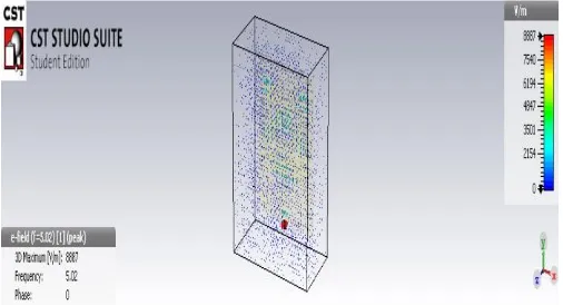
[image:4.595.38.287.96.235.2]Fig -7: Electric field at 5.02GHz-without Tumor
[image:4.595.38.289.310.445.2]From the above figure, it was observed that the antenna has an Electric Field of 8887V/m at 5.0GHz in the absence of Tumor.
Fig -8: Magnetic field at 5.0GHz-without Tumor
[image:4.595.307.562.319.448.2]From the above figure, it was observed that the antenna has a Magnetic Field of 37.4A/m at 5.0GHz in the absence of Tumor.
Fig -10: Current Density at 5.0 GHz-without Tumor
From the above figure, it was observed that the antenna has a current Density of 108A/m^2 at 5.0GHz in the absence of Tumor.
5. CONCLUSION
In this paper, we have designed an antenna for Lung Tumor Detection. The antenna is designed and simulated in CST software. The performance of the proposed antenna is evaluated based on the variations in E-Field, H-Field and current density of the antenna after simulated upon Lung phantom and it is found that the antenna has a current density value of 789 A/m2 which is twice than that of the brain without tumor, E-field of2769V/m which is greater than the lung having no tumor and Magnetic Field of 10.96 A/m which is greater than the lung having no Tumor.
ACKNOWLEDGMENTS
[image:4.595.37.290.531.668.2]© 2017, IRJET | Impact Factor value: 5.181 | ISO 9001:2008 Certified Journal
| Page 3334
REFERENCES
[1] M. Garcia and A. Jemal, "Global Cancer Facts and Figures 2011," Atlanta, GA: American Cancer Society, 2011.
[2] Cancer Statistics 2009,” a presentation from the American cancer society,” American Cancer Soc., 2009.
[3] P.Nivetha, Mr.R.Manickavasagam,” Lung Cancer Detection at Early stage using Ct Imaging Technique,” International Journal of Innovative Research in ComputerandCommunication engineering,Vol.2,Issue 3, March 2014.
[4] Gangotri Nathaney, Kanak Kalyani,” Lung Cancer Detection system on CT images- a Survey” International Journal of Pure and Applied research in Engineering and Technology, Volume 3 (9): 848-856,2015.
[5] Semen N. Semenov, “Imaging the dielectric objects by microwave tomography method,” Journal of physics and Mathematics, vol.1,2015.
[4] M. Guardiola, S. Capdevila, J. Romeu, and L. Jofre, "3-D Microwave Magnitude Combined Tomography for Breast Cancer Detection Using Realistic Breast Models," Antennas and Wireless Propagation Letters, IEEE vol. 11, 2012, pp. 1622-1625.
[5] Y.Serguei and Douglas R. Corfield, "Microwave Tomography for Brain Imaging: Feasibility Assessment for Stroke Detection," International Journal of Antennas and Propagation, vol. 8, 2008. [6] E. Kirshin, B. Oreshkin, G. K. Zhu, M. Popovic, and
M.Coates, "Microwave Radar and Microwave-Induced Thermoacoustics: Dual- Modality Approach for Breast Cancer Detection," Biomedical Engineering, IEEE Transactions on, vol. 60,2013, pp. 354-360.
[7] A. H. Golnabi, P. M. Meaney, S. Geimer, and K. D. Paulsen, "Microwave Imaging for Breast Cancer Detection and Therapy Monitoring," Biomedical Wireless Technologies, Networks, and Sensing Systems (BioWireleSS), IEEE Topical Conference 2011, pp. 59-62.
[8] G. Fei and Z. Yuanjin, "A Correlated Microwave-Acoustic Imaging Method for Early-Stage Cancer Detection," Engineering in Medicine and Biology Society (EMBC), Annual International Conference of the IEEE, 2012, pp. 480-483.
[9] Z. Haoyu, B. Flynn, A. T. Erdogan, and T. Arslan, "Microwave imaging for brain tumour detection using an UWB Vivaldi Antenna array," Antennas and Propagation Conference (LAPC), 2012, pp. 1-4. 6759. [10] M. Aamna, S. Ammar, T. Rameez, S. Shabeeb, N. I. Rao,
and I. Safwat, "2D Beamforming for Through-the-Wall Microwave Imaging applications," in Information and Emerging Technologies (ICIET), 2010 International Conference 2010, pp. 1-6.
[11] X. Li, E. J. Bond, B. D. Van Veen, and S. C. Hagness, "An Overview of Ultra-Wideband Microwave Imaging via Space-Time Beamforming for Early-Stage Breast-Cancer Detection," Antennas and Propagation Magazine, IEEE vol. 47, 2015, pp. 19-34.
[12] M. K. Paul, M. A. K. Sagar, S. U. Hussain, and A. B. M. H. Rashid, "UWB Microwave Imaging via Modified Beamforming for Early Detection of Breast Cancer," Electrical and Computer Engineering (ICECE), International Conference 2010, pp. 642-645.
[13] Hemant Gupta, Vikas Maheshwari and Vandana Vikas Thakery, “Brain Tumor Detection by Microwave Imaging using Planner Antenna,” International Journal of Bio-science and Bio-Technology, vol 8, 2016.
[14] Mohammed A. Alzabidi, Maged A. Aldhaeebi and Ibrahim Elshafiey, “Optimization of UWB Vivaldi Antenna for Tumor Detection,” First International Conference on Artificial Intelligence, Modelling & Simulation, vol. 2, 2013.
[15] Haoyu Zhang, Ahmed O. El-Rayis, Nakul Haridas, Nurul H. Noordin, Ahmet T. Erdogan, Tughrul Arslan, “A Smart Antenna Array for Brain Cancer Detection,” Loughborough Antennas & Propagation Conference, 2011.
[16] CST-Computer Simulation Technology. (2013). 3D Electromagnetic Simulation Software. Available: https://www.cst.com.
[17] "IEEE Recommended Practice for the Measurement of Potentially Hazardous Electromagnetic Fields - RF and Microwave," IEEE Std C95.3-1991, 1992.