© 2018, IRJET | Impact Factor value: 6.171 | ISO 9001:2008 Certified Journal | Page 2133
Power Generation on Highway by using Vertical Axis Wind Turbine &
Solar System
Prof. Sachin Y. Sayais
1, Govind P. Salunkhe
2, Pankaj G. Patil
3, Mujahid F. Khatik
1
Assistant Professor, Dept. of Electrical Engineering, R. C. P. I. T ,Shirpur, Maharashtra, India
2,3,4
UG scholar Dept. of Electrical Engineering, R. C. P. I. T ,Shirpur, Maharashtra, India
---***---Abstract
– This paper focuses on use of air on highwaydivider with the help vertical axis wind turbine. When the vehicle passed on the highway it produces a considerable amount of air due to its speed. This air tangentially strikes on the blade of the vertical axis wind turbine and its makes a rotation of the turbine in only one direction. The solar system is used to generate electrical energy and also installed in a way that it diverts the vehicle air towards the turbine. The generator with the gear mechanism is connected to the shaft of the vertical axis wind turbine to generate electricity. The electrical output of vertical axis turbine and the solar system is stored in a battery. This stored energy which can be further used for street lighting, toll gates, etc.
Key Words: vertical axis Turbine Design, renewable energy source, battery system, solar plates, Highway medium.
1. INTRODUCTION
In a day to day life, the demand for the electricity is much higher than the production of electrical energy. One of the major problems ever since the natural resources are going to finish one day. The fossil fuel major role in production global warming, a greenhouse gas, etc. currently 68 percent of the electrical energy produced by the thermal power plant and remaining 22 percent included hydropower plant, nuclear power plant, gas power plant and as we realized the fossil fuel is finished in one day. Solar and wind both are renewable energy sources. Solar energy available begins of day and the wind energy is maximum on the highway due to the speed of the vehicle. The motivation of this project contributes the global trend toward clean energy.
The main motive behind this project is to design a vertical axis wind turbine which effectively uses the wind energy generated by the vehicle speed on the highway. So the maximum wind energy can be extracted by the vertical axis wind turbine as compared to the horizontal axis wind turbine. We have designed modified savonius vertical axis wind turbine which is more efficient than old savonius design. in modified vertical axis turbine we twisted the blade of the turbine to gain maximum spin on low pressure of the wind, we also try to achieve less vibration at gear moment .This turbine works under all the environmental condition and cyclone also. This design of the blade enables the turbine to rotate in clockwise and anticlockwise directions. The arrangement of solar plats is in such a way
that they divert the vehicle air towards the turbine for effective use of vehicle air. The solar system generates the electrical energy by sun radiation in day mode and from vehicle headlight during night mode the generated electrical energy we can use street lighting, toll gates etc.
2. LITERATURE SURVEY
2.1 Darrieus Vertical Wind Turbine
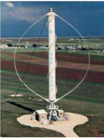
[image:1.595.343.524.505.746.2]The first aerodynamic vertical axis wind turbine was developed by Georges Darrieus in france and first patented in 1927. Its principle of operation depends on the fact that its blade speed is a multiple of the wind speed, resulting in an apparent wind throughout the whole revolution coming in as a head wind with only a limited variation in angle. From the prospective blade, the rotational movement of the blade generates a head wind that combines with the actual wind to form the apparent wind. If the angle of attack of this apparent wind on the blade is larger than zero, the lift force has a forward component that propels the turbine. An angle of attack between zero and 20 degrees requires a sufficiently high blade speed. A Darrieus turbine can’t self starting; it needs to be brought to a sufficiently high blade speed by external means.
© 2018, IRJET | Impact Factor value: 6.171 | ISO 9001:2008 Certified Journal | Page 2134 2.2Variable Geometry Vertical Axis Wind Turbine
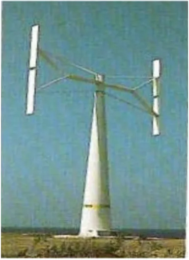
[image:2.595.313.555.76.286.2]P. J. Musgrove in 1975 led a research project at reading University in the UK whose purpose was to attempt to rationalize the geometry of the blades by straightening out of the blades of a Darrieus type wind turbine. This led to design of straight blade vertical axis wind turbine designated as the H rotor blade configuration. At the time it was though that simple H blade configuration could, at high wind speeds, over speed and become unstable. It was thus proposed that reefing mechanism be incorporated into the machine design thus allowing the blades to be feathered in high winds. These machine earlier machines with feathering blades were known as Variable Geometry Vertical Axis Wind Turbines.
Fig -2: Variable Geometry Vertical Axis Wind Turbine
2.3Impulse Savonius VAWT
[image:2.595.65.258.251.516.2]The savonius turbine is a vertical axis machine which uses a rotor that was introduced by Finnish engineer S. J. Savonius in 1922. In its simplest form it is essentially two cups or half drum fixed to a central shaft in opposing direction. Each cup or drum catches the wind and so turns the shaft, bringing the opposing cup or drum into the flow of the wind. This cup or drum then repeats the process, so causing the shaft to rotate further and completing a full rotation. This process continues all the time wind blows and turning of the shaft is used to drive a pump or small generator. These types of windmills are also commonly used for wind speed instrument such as the anemometer. Modern savonius machine have evolved into fluted bladed device, which have a higher efficiency and less vibration than the older twin cup or drum machine.
Fig -3: Impulse Savonius Turbine
3. OBJECTIVE OF PROJECT
The main objective of our project is to use the maximum amount of wind energy from vehicle running on highways. The unused considerable amount of pressurized air used to drive the vertical axis wind turbine from which the kinetic energy of turbine is converted into electrical energy. The main aim of this project to reduce the pollution produced burning of fossil fuel. The generated energy by VAWT and solar system are stored in a battery and this stored energy which can be used street lighting, toll gates or in future to provide the charging node to the electrical vehicle.
4. METHODOLOGY
4.1 Vertical Axis Wind Turbine
The vertical axis wind turbine is used to convert the kinetic energy into mechanical energy. The light weight blade materials (mica sheet) are used for making the vertical axis wind turbine. The height of blade is 1.09 meter and width of blade is 0.33 meter. The whole turbine is assembling with collar and blades which is fitted by nut bolts. To achieve the unidirectional motion of the turbine the blades are bended by 300 angle curve shape and shaft of the
turbine connected to the shaft of generator.
Turbine Specification
Height of blade= 43 inch= 1.09 meter
Height of shaft= 60 inch= 1.52 meter
Helix angle= 300
Vertical shaft diameter= 27 mm
© 2018, IRJET | Impact Factor value: 6.171 | ISO 9001:2008 Certified Journal | Page 2135 Blade weight (mica sheet) = 4 kg
Shaft weight= 1.5 kg
Width of blade= 13 inch= 0.33 meter
Area = diameter * height
= 0.68 * 1.09
[image:3.595.315.555.80.305.2]Area = 0.7412 m2
Fig -4: Modified Savonius Turbine
4.2 Generator Design
4.2.1 Stator
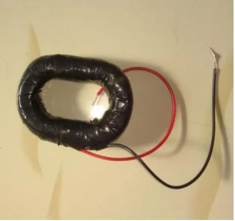
In generator mechanism, 4 coils are used as a stator. The coils are connected in series to achieve desirable voltage from each coil. When the rotor is rotated across winding then the EMF induced on it. The generated EMF is an alternating quantity [1].
Coils Specification
Winding Conductor Gauge = 35
Turns of each coil= 2200 turns
Number of coil= 4
Output voltage= 60-85 volts (Depending on speed of rotation)
Fig -5: Coils
4.2.2 Rotor
In generator mechanism, a rotor is consisting with permanent magnet placed around the stator. The shape of this permanent magnet is a square . When a rotor is rotated it produced a rotating magnetic field which link with the stator coil and generate EMF in stator coil. The type of magnet used for rotor circuit is neodymium strong magnet.
Specification of Permanent Magnet
Neodymium strong magnet= 4 (square magnet)
Plating= Nickel + copper
Size= 25mm*25mm*12mm
4.2.3 Battery
A valve regulated lead acid battery sometimes called sealed lead-acid (SLA), gel cell, or maintenance free battery. Due to their construction, the Gel and Absorbent Glass Mat types of VRLA can be mounted in any orientation, and do not require constant maintenance. They are widely used in large electrical devices, off-grid power systems and similar roles, where large amounts of storage are needed at a lower cost than other low-maintenance technologies like lithium-ion.
Specification of Battery
Voltage Range= 12 Volt.
Current Range= 12 Ah.
[image:3.595.70.254.209.483.2]© 2018, IRJET | Impact Factor value: 6.171 | ISO 9001:2008 Certified Journal | Page 2136 Fig -5: Battery
4.3 Block Diagram
Fig -5: Block Diagram
5. WORKING PRINCIPLE
The moving vehicle on highway may be all types such as small or heavy vehicles. Whenever vehicle moves on both side of the highway divider then some pressurized air is produced due to the speed of vehicle. This pressurized air is strike on the blade of vertical axis wind turbine and turbine makes a rotation. The shaft of the vertical axis wind turbine is connected to generator with the help of gear mechanism. The generated electricity is an alternating quantity; the output of the generator is rectified by rectifier and stored in the battery. The solar system is mounted on besides of the
vertical axis wind turbine, the function of the solar system not only generate the electricity but also provides the constant air flow towards the blade of vertical axis wind turbine. The position of solar plates is in inclined nature at an angle 45 degree.
A solar cell or photovoltaic cell is an electrical device that converts the energy of light directly into electricity by the photovoltaic effect, which is the physical and chemical phenomenon. It is photoelectric cell, defined as a device whose electrical parameter such as current, voltage or resistance varies when exposed light. Solar cells are the building blocks of photovoltaic modules. The generated electricity is stored in the battery. The stored energy used as a street lighting and domestic purpose [2].
6. RESULT
Speed of Turbine (RPM) Output Voltage (AC)
150 65
200 75
275 87
© 2018, IRJET | Impact Factor value: 6.171 | ISO 9001:2008 Certified Journal | Page 2137
REFERENCES
1] Mithun K K and Ashok S “Wind Turbine for Highway Wind Power Generation” IJEEE, Volume 07, Issue 01, Jan- June 2015.
2] Dhiraj Varma and Ajitabh Pateriya “VAWT and Solar Panel Combine System Based Generation of Electricity through Highway" IJRISE, Vol.3, 2017. pp: 137-140.
3] S.Selvam, Edison Prabhu .K, Bharath Kumar M.R, & Andrew Mathew Dominic “Solar and Wind Hybrid power generation system for Street lights at Highways” International Journal of Science, Engineering and Technology Research (IJSETR), Volume 3, Issue 3, March 2014.
4] Scheurich, Frank, and Richard E. Brown “Modelling the aerodynamics of vertical axis wind turbines in steady wind conditions" Wind Energy 16.1 (2013): 91-107.
5] Shweta Singh, Sarita Singh and Priyank Srivastava “Vertical Axis Wind Turbine for Generation of Electricity through Highway Windmill” S-JPSET: Vol. 7, Issue 2, ISSN: 2229-7111
6] Krishnaprasanth.B , Akshaya.P.R , Mr.Manivannan.L, Ms.Dhivya.N “A New Fangled Highway Wind Power Generation” International Journal for Research in Applied Science & Engineering Technology (IJRASET) Volume 4 Issue I, January 2016.
AUTHORS
Prof Sachin Y Sayais
Assistant Professor, Dept. of Electrical Engineering, R. C. P. I. T ,Shirpur, Maharashtra, India
Mr Govinda P Salunkhe UG scholar RCPIT shirpur
Mr Pankaj G Patil
UG scholar RCPIT shirpur