© 2018, IRJET | Impact Factor value: 6.171 | ISO 9001:2008 Certified Journal | Page 4181
STUDY AND IMPLEMENTATION OF HARMONIC DRIVE IN CNC LATHE
Abdulla Munaver V K
1, Akhil P
2, Amal AS
3, Saleekh Muhammed P
4,
Thomas Jacob
5, Linto P Anto
61,2,3,4
B-Tech Student, Department of Mechanical Engineering, Mar Athanasius College of Engineering,
Kothamangalam, Kerala, India
5
Assistant Professor, Department of Mechanical Engineering, Mar Athanasius College of Engineering,
Kothamangalam, Kerala, India
6
Deputy Engineer, Design Section, HMT Ltd, Kalamassery, Kerala
---***---Abstract
- Milling operations are difficult to perform in CNC turning centres due to lack of control over speed, positional accuracy, and repeatability and required machining torque. It is a secondary gear box which drives the spindle while the gearbox is in neutral. The key features we need while performing milling operation is high torque and high speed reduction for the better positioning of the work piece. C- Axis gear drive work on its worm wheel and gear assembly is able to satisfy this need to an extent. But the problem regarding this drive is that they are bulky and their repeatability and positional accuracy is less. Our aim is to study the existing c-axis drive and find a better drive that can replace c- c-axis drive. Harmonic drives are better technology which can provide better features than c-axis. A harmonic gear drive gives more speed reduction and power transmission capacity compared to conventional gear system. Harmonic drive provides accurate as well as precision with much less space as compared to any other power transmission drives.Key Words
: Harmonic drive, C-axis, CNC lathe, Stress analysis, Total Deformation1. INTRODUCTION
Usually CNC turning centers are used for turning, taper turning, drilling, boring, contouring with linear and circular interpolation, internal and external threading (parallel or taper) etc. Milling operations are difficult to perform in CNC turning centers due to lack of control over speed, positional accuracy, repeatability and required machining torque. Harmonic drive is a type of mechanical gear system also known as a “strain wave gear” which employs continuous deflection wave along a non-rigid gear to allow for gradual engagement of gear. The advantages include: compactness and light weight, high gear ratios, no backlash, reconfigurable ratios within a standard housing, good resolution and excellent repeatability when repositioning inertial loads, high torque capability, and coaxial input and output shafts. High gear reduction ratios are possible in a small volume .The strain wave gearing theory is based on elastic dynamics and utilizes the flexibility of metal.
2. DESIGN OF EXISTING GEARBOX
This arrangement consists of an input motor and the shaft is run by a motor. The shaft being a worm shaft transmit power to a worm gear. A spur gear is attached to the same spindle
of worm gear. The output is carried out by a large spur gear to the different operations.The various parameters like no . of teeth, module, pitch diameters etc. should be designed.
Module m = 1.26
*
[image:1.595.309.559.612.780.2]Where y, Ψ is chosen from PSG data book, σ is the stress and Z2 no teeth on pinion. The material chosen is structural steel.
Table.1 Specifications of both gear pair
Wheel Pinion
Material Steel Steel
Diameter 288 mm 144mm
No of teeth 144 72
Module 2 mm 2 mm
Addendum 2mm 2 mm
Dedendum 3mm 3mm
Face width 18.84 mm 18.84 mm
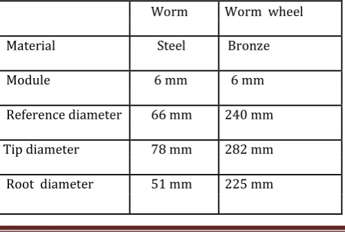
Table.2 Specifications of worm gear
Worm Worm wheel
Material Steel Bronze
Module 6 mm 6 mm
Reference diameter 66 mm 240 mm
Tip diameter 78 mm 282 mm
© 2018, IRJET | Impact Factor value: 6.171 | ISO 9001:2008 Certified Journal | Page 4182 Length of worm 96.6 mm -
Centre distance 153 mm -
No.of teeth 2 40
Face Width - 49.5mm
Oldham coupling: a coupling for parallel shafts slightly out of line consisting of a disk on the end of each shaft and an intermediate disk having two mutually perpendicular feathers on opposite sides that engage slots in the respective shaft disks
Table.3 Specifications of Oldham coupling
Description Value (mm)
Shaft diameter 20.90
Outside Diameter 80
Hub Diameter 40
Thickness of Tongue 9
Axial Dimension 4.5
Power of the spindle, P = 0.2504 kW Torque of the spindle, T = 239.11 Nm Torque of the motor, T = 5.98 Nm
From the SIEMENS motor catalogue the selected servo motor is ,
Motor Type = IFK7062
Power , P = 1.34 kw
Current , A = 10.9 amp
Speed , N = 2000rpm
3. C AXIS DRIVE ASSEMBLY
C-axis drive is an attachment to the gear box which helps to do the milling operations in turning centers, to index the job at different angles required and also run the spindle at smaller rpm at high torque. With this attachment we can perform the various milling operations such as key way milling, counter hole drilling, offset drilling, groove cutting in
different shape etc. This arrangement consists of an input motor and the shaft is run by a motor. The shaft being a worm shaft transmits power to a worm gear. A spur gear is attached to the same spindle of worm gear. The output is carried out by a large spur gear to do the different operations. Certain limitations of C axis drive are : C- axis drive assembly makes the lathe more bulky and increases the weight of the machine, higher ratio speed reduction is not possible, expected higher torque cannot be provided with C- axis assembly, repeatability is less, chances of wear is more, chances for increase in backlash error increase with time period of operation, less drive efficiency, load carrying capacity is less, lack of consistent performance due to backlash error . The 3D model of the existing gear box of the c axis drive assembly made by using Autodesk Inventor software is shown below:
Figure 1 Isometric view of the model
Figure 2 Front view of the model
4. SELECTION OF HARMONICDRIVE
After calculating the milling torque required , the harmonic drive has to be selected in the specific range . The company supplying harmonic drive is Harmonic drive AG
HARMONIC DRIVE AG
© 2018, IRJET | Impact Factor value: 6.171 | ISO 9001:2008 Certified Journal | Page 4183 interest to many other application areas . Since its inception
over 40 years , Harmonic Drive AG has transformed itself into company offering the solution of choice for high precision or planetary drives the more demanding the task , the better . The company offer more than 23,000 different products, of which more than 80% are customers specific solutions.
Harmonic Drive AG and its products are being used in many different industries . Currently we offer drive solution for use across many application sectors including : Robotics and Automation, Machine Tool, Semiconductor Technology, Medical Technology , Packing Machines, Defense Technology and Aerospace.
HFUC – 2UH
Harmonic Drive units combine the precision Harmonic Drive component sets consisting of three components - circular Spline , Flex spline and wave generator and integral high load capacity tilt resistant output bearings.
The available series of HFUC-2UH are listed in table below:
HFUC-2UH Series units are available in thirteen sizes with gear ratios of 30,50,80,100,120 and 160:1 offering repeatable peak torques from 9 to 9180 Nm. The output bearing with high tilting rigidity enables the direct introduction of high payloads without further support and thus permits simple and space saving design installations . The units are available as specific configurations tailored to application and can utilize standard servo motors. Unit and motor together form a compact and lightweight system capable of withstanding high loads. On request the series is available for ambient temperatures between -40 and 90 0c and can be used with large selection of accuracy, stable machine characteristics with short cycle times are guaranteed. The main features of HFUC-2UH are
• Easy to customize • Direct motor connection • Excellent life time precision • Compact , lightweight design
• High dynamics
• Integrated high capacity output bearing
© 2018, IRJET | Impact Factor value: 6.171 | ISO 9001:2008 Certified Journal | Page 4184 In this desired range , the series matching to our motor
[image:4.595.303.564.59.281.2]torque is HFUC-17-2UH , where speed ratio is 100 . The illustration of HFUC-17-2UH is given below:
Figure 3 Drawing of HFUC-17-2UH
5. THE STATIC ANALYSIS OF THE MODEL
The safety of the design is a great factor. The modern powerful analysis software’s help us to make detailed analysis on our design. The objective is to analysis the stress concentrated points in the model. A meshed view of the model is shown in figure 4, the results of the stress analysis is provided in figure 4 and the results of total deformation analysis is given in figure 5, distribution of equivalent stresses are shown in figure 6.
[image:4.595.51.278.147.363.2]Figure 4 Mesh figure of model
[image:4.595.309.563.319.519.2]Figure 5 Contour of equivalent stress
Figure 6 Contour of equivalent strain
[image:4.595.38.566.528.742.2]© 2018, IRJET | Impact Factor value: 6.171 | ISO 9001:2008 Certified Journal | Page 4185
7. CONCLUSION
Harmonic Drive gears have a long success story in demanding machine tools applications. The range of applications is increasing quickly due to continuous product development, which is leading to greatly improved product performance. Harmonic drive gears are one of the newer gears which have no internal backlash. Harmonic drive gears have other
Advantages such as high capacity output bearing, high torque capacity, excellent positioning accuracy and repeatability, compact design, high single stage ratios, high torsional stiffness, high efficiency, simple installation and assembly etc. Usually, lathe is used for turning and drilling operations. Milling and shaping operations are difficult to perform in lathe due to lack of control over speed and tension. This is done by replacing a harmonic drive system over the conventional gear system. A harmonic gear drive gives more speed reduction and power transmission capacity compared to conventional gear system. Harmonic drive provides accurate as well as precision with much less space as compared to any other power transmission drives. Essential difference between harmonic drive and conventional gear drive is that flex spline in the harmonic drive is flexible and the center distances of teeth vary continuously during meshing.
8
.
ACKNOWLEDGEMENT
This paper is the outcome of hard work with the help and co- operation from many sources. We express our gratitude and sincere thanks to college management and all the faculties of the department of mechanical engineering, Mar Athanasius College of Engineering. Authors are thankful to Design section, Hindustan Machine Tool Ltd for their support and guidance.
9. REFERENCES
[1].PSG College of Technology, “Design Data”, Kalai kathir Achchangam Publications
[2].Meshing Analysis of Teeth of Harmonic Drives: A Computer Based Approach , A.J. Bamnote , Prasad Mahale and Rahul Gulhane , Dept. Of Mechanical Engg. Y.C. College Of Engg. Nagpur.
[3].Modelling and Parameter Identification of Harmonic Drive Systems , H.D Taghirad and P.R Belanger , Centre for Intelligent Machines ,Department of Electrical Engineering ,McGill University Montreal H3A 2A7.
[4].Design and Analysis of Flex Spline with Involute Teeth Profile for Harmonic Drive Mechanism, Y. S. Hareesh and James Varghese , Assistant Professor, Mechanical Engineering Department ,College of Engineering & Management, Punnapra
Alapuzha, Kerala, India , (IJERT) ISSN: 2278- 0181 Vol. 4 Issue 12, December-2015
[5].R.S Khurmi, J.K Gupta, “Machine Design”, Eurasia Publishing House
[6].Development of the harmonic drive gear for space applications , Keiji Ueura & Dr. Rolf Slatter
[7].Analysis of Flexspline in the Harmonic Drive System: A Review ,Sandeep Kumar Awasthi , Rajesh Kumar Satankar , Government Engineering College, Jabalpur-482004, MP, India. Department of Mechanical Engineering Jabalpur Engineering college, Jabalpur, M.P, India , ISSN: 2277-9655 , IJESRT
[8] . Restov., Strain Wave Gearing, Machine Design., MIR Publishers, Moscow.
[9].R.S Khurmi, J.K Gupta, “Machine Design”, Eurasia Publishing House