2018 International Conference on Computer, Communication and Network Technology (CCNT 2018) ISBN: 978-1-60595-561-2
Dynamic Modeling and Nonlinear Control of Spherical-wheeled Robot
Xiao-gang RUAN and Tong LIU
*Artificial Intelligence and Robot Institute, Beijing, 100124, China
*Corresponding author
Keywords: Spherical-wheeled robot, Lagrange equation, Dual loop control, Nonlinear PD control.
Abstract. In this paper, a novel self-balancing spherical-wheeled robot is proposed, which can omnidirectional move in plane. Firstly, the mechanical structure of a robot is given. Secondly, the complete dynamic model of the robot system is established by Lagrange equation. Thirdly, A nonlinear PD controller is proposed, and experiments are carried out in MATLAB. The results show that the control strategy can realize the balance control of the robot with good response characteristics and stability.
Introduction
The spherical self-balancing mobile robot is a kind of dynamic stability of mobile robot, unlike the common self-balancing robot, the spherical-wheeled robot has no turning radius, which means it does not have to make a turn. Therefore, it is more flexible than other land mobile tools. Its ability to move in all directions can improve its performance in narrow, crowded and dynamic environments.
Self-balancing robot [1] developed as early as 1986, originated in Japan, the initial idea is to design a machine that can stand automatically. In 1986, Professor K.Y. of Nippon Telekom University conceived an automatic standing robot [2], but the robot can only move forward on a fixed track. In 1996, Y.S.H. and S.Y. of Tsukuba University designed and implemented a two-wheeled robot. It uses a three-stage closed-loop control system to control the autonomous cruising of the robot in a plane [3]. In 2002, F.G. developed the JOE [4]. It can walk freely on slopes due to its centralized structure. In 2005, Professor R.H. at Carnegie Mellon Institute of Robotics and his team successfully developed the first ball-wheel robot, and named BALLBOT [5]. In 2008, The Murata girl was introduced in the Japan Robot Exhibition [6]. It maintains the lateral balance by turning the flywheel equipped in the robot body. In 2010, the REZERO was introduced by University of Zurich [7], which using the LQR control algorithm. This is a representative of the spherical self-balancing robot.
The spherical-wheeled robot as a class of system with multi-degrees of freedom, underactuation and highly coupled nonlinear. Therefore, most research carry out the linearization of their model in the study, using classical control theory to solve such problems, as described in [5]-[7]. most simulation experiments are generally based on the mathematical model, as described in [3],[4]. But mathematical model often cannot truly reflect the actual situation of the robot.
In order to solve these problems mentioned above. A nonlinear PD controller is proposed to control the attitude balance of the robot. In order to solve the mathematical model inaccurate problem, we simulate in the virtual prototype environment [8]. The experiment results show that the controller realizes the accuracy and robustness of the robot control.
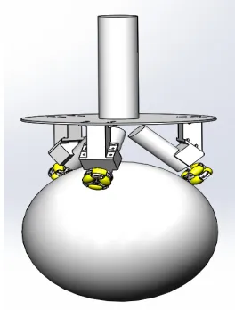
The Spherical-wheeled Robot
Figure 1. The spherical-wheeled robot. Figure 2. The planar decomposition model.
The Dynamic Model of the Robot
Dynamic Model
Considering that the robot is only moving on the plane, the robot has three rotational degrees of freedom and two translational degrees of freedom. All the five degrees of freedom are taken as the generalized coordinates of the Lagrange equation, and the dynamic model of the robot is established by using the Lagrange equation method. The planar decomposition model of the robot is shown in Figure 2.
The generalized coordinates of the fetching system
( )
, ,
x y
yz xz xy z
q q q
x y
θ θ
θ
= = =
(1)
Where θx,y,z are the rotation angles of the robot separately, x,y are the displacements of the
spherical wheel separately.
We discuss the kinetic energy and potential energy of the system in yz plane, the xz plane and xy plane is similar to that of the yz plane.
The kinetic energy of the spherical wheel
2
2
1 1
2 2
B B B
B
x
T m x I
r
= +
(2) The potential energy of the spherical wheel
0
B V =
(3) The kinetic energy of the driving wheel
2
2
1 1
2 2
B
W W W x x
W B
r x
T m x I
r r θ θ
= + − −
(4) The potential energy of the driving wheel
(
)
cosW W B W x
T =m g r +r θ
(
)
(
2 2 2 2)
1
2 cos 2
A A x x x A x
T = m x + l θ θx+l θ +I θ
(6) The potential energy of the body
cos
A A x
V =m gl θ
(7) The Lagrange equation [9] is obtained as follows
T T T
N
d T T V
F
dt q q q
∂ ∂ ∂
− + =
∂ ∂ ∂
(8)
Where T=TB+TW+TA, V=VB+VW+VA.
We take as the state variable of system, The dynamic modeling can be expressed as state space form
(
)
(
)
1 yz yzx N x x
yz
q q
M F C G
q − = − + (9) where 11 12 21 22 x M M M M M =
(10)
(
)
2 2
11 m m r
B
A B W B B W
W r
M m I I
r
= + + + +
(11)
(
)
12 21 2 cos
B
B W W B x
W r
M M r r I r
r θ = = − + + (12)
(
)
(
)
2 2 2 22 2 B WW A A W B W
W
r r
M I I m l m r r
r +
= + + + +
(13)
(
)
(
)
2sin
0
B A B W W x x
x
r lm r r m
C θ θ
− + + = (14)
(
)
(
)
0 sin xx A B W W
G
g θ lm r r m
=
− + +
(15)
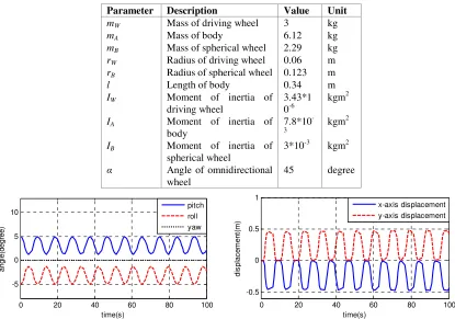
FN is the torque generated by driving wheel. mW, mA, mB denote the mass of the driving wheel, the body and the spherical wheel separately. rW, rB denote the radius of the driving wheel and the spherical-wheel separately. l is the length of the body. IW, IA, IB represent the moments of inertia of the driving wheel, the spherical wheel and the body separately. g is the gravity acceleration.The value of parameters are set in Table 1.
Mode Verification
factors. The variation curve of the roll angle and pitch angle should do equal amplitude oscillation motion, and the robot should swing back and forth. Figure 3 and Figure 4 show the simulation curve. According to Figure 3 and Figure 4, the roll angle and the pitch angle do equal amplitude oscillation motion and the robot swing back and forth. So the results show that the exact model is correct.
Table 1. Parameters of the robotic system.
Parameter Description Value Unit
mW Mass of driving wheel 3 kg
mA Mass of body 6.12 kg
mB Mass of spherical wheel 2.29 kg
rW Radius of driving wheel 0.06 m
rB Radius of spherical wheel 0.123 m
l Length of body 0.34 m
IW Moment of inertia of
driving wheel
3.43*1 0-6
kgm2
IA Moment of inertia of
body
7.8*10
-3 kgm
2
IB Moment of inertia of
spherical wheel
3*10-3 kgm2
α Angle of omnidirectional
wheel
45 degree
0 20 40 60 80 100
-5 0 5 10
time(s)
a
n
g
le
(d
e
g
re
e
)
pitch roll yaw
0 20 40 60 80 100
-0.5 0 0.5 1
time(s)
d
is
p
la
c
e
m
e
n
t(
m
)
x-axis displacement y-axis displacement
Figure 3. The variable curve of angle. Figure 4. The variable curve of displacement.
Controller Design
In the above modeling process, the driving torque is the fictitious virtual torque of each plane, the purpose of this is to solve the coupling between plane models, which makes it convenient to design the controller of the robot.
[image:4.612.235.380.545.695.2]The relationship between the actual torque and the virtual torque is shown in Figure 5.
Figure 5. Torque diagram.
(
)
1
1 2
cos sin
3 Z cos X Y
T T T β T β
α
= + −
(16)
(
)
(
)
2
sin 3 cos 3
3 3cos
X Y X Y
Z
T T T T
T
T β β
α
− + − +
= +
(17)
(
)
(
)
3
sin 3 cos 3
3 3cos
X Y X Y
Z
T T T T
T
T β β
α
− + + − +
= +
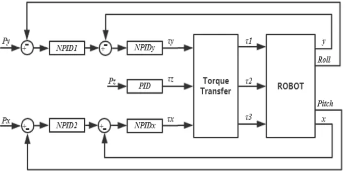
[image:5.612.136.478.286.460.2](18) The control system of the robot is decomposed into two synchronous operation control systems: one is balance control, that is, the body maintains the balance posture; the other is motion control which is to control the displacement of robot. The balance control is the basis. The actual demand requires robots to complete their designated movements while maintaining their own balance. As the linear control methods are difficult to achieve a more satisfactory control effect. So we propose a double closed-loop control system based on nonlinear PID (DLNPD), includes the outer loop attitude controller and the inner loop displacement controller, as shown in Figure 6.
Figure 6. Control block diagram of the DLNPD.
As a class of under-driven robots, the primary task of the spherical self-balancing robot is to maintain its posture balance. In this paper, three nonlinear PD controllers are set up respectively in the pitch direction, roll direction and yaw direction. In the balance control of the robot, the reason for selecting PD control instead of PID control is that the noise signals are unavoidable in the gesture detection. Those noise signals are accumulated over time through the integral link, which can cause the integrator lose the adjustment function of the net offset and produce the control error. Compared with PD control, the nonlinear PD control has the advantages of large control margin and high robustness, and it is not easy to produce self-oscillation near the equilibrium point. The control algorithm is as follows.
( ) ( ) ( ) ( )
tot P D
d
u t PD K K
dt
θ
θ θ
= = +
(19) Where
( )
tan( )p P
K θ =K ωθ
(20)
2
( ) sgn( )
D D
K θ = θ K θ
Simulation
In accordance with the parameters of Table 1, the control system designed in the previous section is applied to the attitude balance control of the robot. We have done some experiments to adjust the parameters of controller. Finally, the parameters of NPID1 and NPID2 are KP=45, ω=0.85,
KD=4.5,the parameters of NPIDx and NPIDy are KP=25, ω=0.4, KD=2.
We carry out simulation experiments in MATLAB/SIMULINK environment. The comparative experiments with PID and DLNPD are proposed. The parameters of PID controller that have a best effect are set as KP=60, KI=35, KD=16.
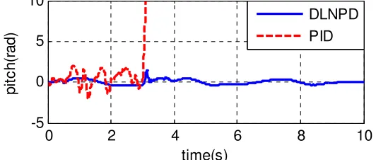
Let initial state of the spherical-wheeled robot is
(
/ 6, 0, 0, 0)
T x= π
, that is to say declination of the spherical-wheeled robot is π / 6 rad, other initial values of input are all zero. From the figure 7, the results show that the DLNPD is much better than PID. The overshot of DLNPD is less than PID, also the response speed, rise time and adjusting time of DLNPD is faster than PID.
0 2 4 6 8 10
-0.2 0 0.2 0.4
time(s)
p
it
c
h
(r
a
d
)
PID DLNPD
0 2 4 6 8 10
-5 0 5 10
time(s)
p
it
c
h
(r
a
d
)
[image:6.612.88.517.254.354.2]PID DLNPD
Figure 7. The pitch angle. Figure 8. The variable curve of pitch angle.
Robustness of the controller would be verified as following, at the beginning the robot is being a state of balance. The white noise has been joined in system, response curve as showed in figure 8. Simulation results show that the robustness of DLNPD is better than PID controller.
With the white noise joined in system. At t=3s, we apply an impact disturbance of about 100Nm in the direction of the robot's pitching for 0.1 seconds. Response curve of system as showed in Figure 9. Simulation results show that the DLNPD controller can stabilize the robot, while the PID controller cannot.
0 2 4 6 8 10
-5 0 5 10
time(s)
p
it
c
h
(r
a
d
)
DLNPD PID
Figure 9. Robustness experiment.
Conclusion
[image:6.612.165.431.472.585.2]Acknowledgement
The research is supported by the Natural Science Foundation of China (61075110) and Beijing Natural Science Foundation (4174083)
References
[1] Yamafuji K, Kawamura T. Postural control of a monoaxial bicycle.[J]. Journal of the Robotics Society of Japan, 2010, 7(4):338-343.
[2] Koshiyama A, Yamafuji K. Design and Control of an All-Direction Steering Type Mobile Robot[J]. International Journal of Robotics Research, 1993, 12(5):411-419.
[3] Tani J, Fukumura N. Learning goal-directed navigation as attractor dynamics for a sensory motor system. (An experiment by the mobile robot YAMABICO)[C]// International Joint Conference on Neural Networks, 1993. IJCNN '93-Nagoya. IEEE, 2002:1747-1752 vol.2.
[4] Grasser F, D'Arrigo A, Colombi S, et al. JOE: a mobile, inverted pendulum[J]. IEEE Transactions on Industrial Electronics, 2002, 49(1):107-114.
[5] Nagarajan U, Kantor G, Hollis R. The ballbot: An omnidirectional balancing mobile robot[J]. International Journal of Robotics Research, 2013, 33(6):917-930.
[6] Colli V, Tomassi G, Scarano M. "Single Wheel" longitudinal traction control for electric vehicles[J]. IEEE Transactions on Power Electronics, 2006, 21(3):799-808.
[7] Park J H, Kim S C, Yi S. Development of Stable Ballbot with Omnidirectional Mobility[J]. Journal of Institute of Control, 2013, 19(1):40-44.
[8] Hao Y T, Jin Y, Hui J I. Virtual prototype technology and its practice on ADAMS[J]. Machinery Design & Manufacture, 2003.