International Journal of Scientific Research and Engineering Development-– Volume2 Issue 2, Mar –Apr 2019 Available at www.ijsred.com
ISSN : 2581-7175 ©IJSRED:All Rights are Reserved Page 696
Study on Behaviour of Beam Column Joint with HSC
& HPFRC
1PA.Saipraveen,
2S.Govindhan
1PG Scholar, M.E-StructuralEngineering, Department of CivilEngineering, SembodaiR.V Engineering College,Sembodai -614820
2Assistant ProfessorDepartment of CivilEngineering, SembodaiR.V Engineering College,Sembodai -614820
---
************************
---Abstract:Beam column joint is a significant structural element for which, have to give a almost care in order to
uphold the structures when subjected to the reversal of forces during earthquake. To satisfy the intended
function of beam column joint it is essential to ensure the factors such as ductility, stiffness degradation
and energy absorption capacity. In due course the joint should be flexible enough to undergo substantial
shear deformation. This study illustrates the performance of two exterior beam column joints which have
been modelled to a one fourth scale from a two bay six storey moment resisting frame subjected to cyclic
loading. The joints are detailed as per the provisions given in IS 13920:1993 using M60 High Strength
Concrete (HSC) and High Performance Fibre Reinforced Concrete(HPFRC) and High Performance Fibre
Reinforced Concrete(HPFRC) with modified spacing. 1% of steel fibre is added based on volume fraction
to enhance the joint strength, ductility and energy absorption capacity.
---************************---1. INTRODUCTION
1.1 GENERAL
The performance of beam column joint plays a
major role while considering the consequences
occurred during earthquake in moment resisting
frame structures. There are mainly three types of
joints that can be identified, namely, interior joint,
exterior joint and corner joint. In these three types
exterior joint is most crucially affected during the
severe external loading applied. So that exterior
beam column is taken into account in this study.
The basic requirement of design is that the joint
must be stronger than the adjoining beam and
column member. It is important to see that the joint
size is adequate in the early design phase; otherwise
the column or beam size will have to be suitably
modified to satisfy the joint shear strength or
anchorage requirements. The design of beam
column joint is predominantly focused on providing
the joint shear strength and adequate anchorage
International Journal of Scientific Research and Engineering Development-– Volume2 Issue 2, Mar –Apr 2019 Available at www.ijsred.com
ISSN : 2581-7175 ©IJSRED: All Rights are Reserved Page 697 within the joint. A review of the behaviour and
design of different types of beam column joints in
reinforced concrete moment resisting frames under
seismic loading illustrates that design and detailing
provisions for the joints in the current Indian
seismic codes IS 13920:199 and IS 1893:2002 are
available to ensure prevention of brittle failure due
to large shear forces which develop in the joint
during earthquake.
Besides these, there are a large number of
investigations on the effect of addition of steel
fibres on the strength and ductility of flexural
members. That study indicates that ductility and
ultimate resistance of flexural members are
remarkably enhanced due to the addition of steel
fibres. Also it was emphasised that the neglect of
fibre contribution may considerably underestimate
the flexural capacity of fibre reinforced concrete
beams. In general, when fibres are added to the
concrete, tensile strain in the neighbourhood of
fibres improves significantly. In this investigation,
there is a considerable improvement in strength,
ductility and energy absorption capacity with the
addition of steel fibre as compared with the normal
high strength concrete.
1.2 SIGNIFICANCE OF CONCRETE
Concrete is one of the most durable building
materials. It provides superior fire resistance
compared with wooden construction and gains
strength over time. Structures made of concrete can
have a long service life. Concrete is used more than
any other manmade material in the world. Concrete
has high compressive strength, its tensile strength is
very low. In situations where tensile stresses are
developed, the concrete is strengthened by steel
bars or short randomly distributed fibers forming a
composite construction called Reinforced cement
concrete (RCC) or fiber reinforced concrete. In
addition to its good compressive strength, concrete
has flexural and splitting tensile strengths too.
Concrete is a non-combustible material which
makes it fire-safe and able to withstand high
temperatures.Plain concrete possess very low
tensile strength, limited ductility and little
resistance to cracking. Internal micro cracks are
inherently present in the concrete and its poor
tensile strength is due to the propagation of such
micro cracks, eventually trading to brittle failure of
the concrete. In plain concrete structural cracks
develop even before loading particularly due to
shrinkage or other causes of volume change.
1.3 DRAWBACKS OF CONCRETE
● Concrete has low tensile strength and hence
cracks easily.
● Concrete expands and contracts with the
changes in temperature.
● Fresh concrete shrinks on drying. It also
expands and contracts with wetting and
International Journal of Scientific Research and Engineering Development-– Volume2 Issue 2, Mar –Apr 2019 Available at www.ijsred.com
ISSN : 2581-7175 ©IJSRED: All Rights are Reserved Page 698 ● Concrete is not entirely impervious to
moisture and contains and contains soluble
salts which may cause efflorescence.
● Concrete prepared by using ordinary Portland
cement disintegrates by the action of Alkalies,
Sulphates, etc.
● The lack of ductility is inherent in concrete
as a material is disadvantageous with respect
to earthquake resistant design.
● To overcome this drawback fiber is used in
concrete.
1.4 FIBER-REINFORCED CONCRETE (FRC)
Fiber reinforced concrete is concrete containing
fibrous material which increases its structural
integrity. It contains short discrete fibers that are
uniformly distributed and randomly oriented. Fibers
include steel fibers, glass fibers, synthetic fibers and
natural fibers – each of which lends varying
properties to the concrete. In addition, the character
of fiber-reinforced concrete changes with varying
concretes, fiber materials, geometries, distribution,
orientation, and densities.
Fiber is a small piece of reinforcing material
possessing certain characteristic properties. They
can be circular or flat. The fiber is often described
by a convenient parameter called “aspect ratio”.
The aspect ratio of the fiber is the ratio of its length
to its diameter. Typical aspect ratio ranges from 30
to150.
1.4.1 PROPERTIES OF FIBER REINFORCED
CONCRETE
● Controls cracking due to plastic shrinkage
and drying shrinkage.
● Reduce the permeability of concrete and thus
reduce bleeding of water.
● Reduce steel reinforcement requirements
● Improve impact resistance and abrasion
resistance.
● Improve ductility.
● Reduce crack widths and control the crack
widths tightly, thus improving durability.
1.4.2 ROLE OF FIBER REINFORCED
CONCRETE
● The use of fibers in reinforced concrete
flexure members increases ductility, tensile
strength, moment capacity, and stiffness
● It increases stiffness, torsional strength,
ductility, rotational capacity and the
number of cracks with less crack width
● Addition of fibers increases shear capacity
of reinforced concrete beams up to 100
percent
● Addition of randomly distributed fibers
increases shear-friction strength, the first
crack strength, and ultimate strength
● The use of fibers helps in reducing the
International Journal of Scientific Research and Engineering Development
©IJSRED: All Rights are Reserved 1.4.3 TYPES OF FIBERS
There are various fibers are used in the concrete.
Some of them listed below
● Steel fiber
● Glass fiber
● Carbon fiber
● Polypropylene fiber
● Natural fiber
● Basalt fiber
● Asbestos fiber
● Aramid fiber
1.4.3 (a) STEEL FIBER
The superior structural properties of SFRC have
found it an ideal material for overlays and over slab
of roads, pavements, airfields and bridge decks,
industrial and other flooring units those subjected to
wear and tear and attack due to chemical effects.
Fig 1.1 Steel Fiber
1.4.3(b) GLASS FIBER
Glass fibers are produced commercially in three
basics forms, namely, ravings, strands and woven
or chopped strand mat. There are however, two
main problems is the use of glass fibers in Portland
International Journal of Scientific Research and Engineering Development-– Volume2 Issue 2, Mar Available at www.ijsred.com
©IJSRED: All Rights are Reserved There are various fibers are used in the concrete.
The superior structural properties of SFRC have
found it an ideal material for overlays and over slab
of roads, pavements, airfields and bridge decks,
industrial and other flooring units those subjected to
ue to chemical effects.
Glass fibers are produced commercially in three
basics forms, namely, ravings, strands and woven
or chopped strand mat. There are however, two
main problems is the use of glass fibers in Portland
cement products, namely, the breakage of fibers and
the surface degradation of the glass by the high
alkalinity of the hydrated cement paste. Glass fiber
has roughly comparable mechanical properties to
other fibers such as polymers and carbon fiber.
Although not as strong or as rigid as carbon fiber, it
is much cheaper and significantly less brittle when
used in composites.
Fig1.2 Glass fiber
1.4.3(c) CARBON FIBER
Carbon fibers have high tensile strength and
young’s modulus, but also a high specific strength
compared to steel and glass fibers. Increase in
flexural strength, and stiffness are about 214 kg/cm
and 21420 kg/cm2 respectively for the one percent
of fiber. The properties of carbon fibers, such as
high stiffness, high tensile strength, low weight,
high chemical resistance, high temperature
tolerance and low thermal expansion, make them
very popular in aerospace, civil engineering,
military, and motorsports, along with other
competition sports
Volume2 Issue 2, Mar –Apr 2019 www.ijsred.com
Page 699 cement products, namely, the breakage of fibers and
ace degradation of the glass by the high
alkalinity of the hydrated cement paste. Glass fiber
has roughly comparable mechanical properties to
other fibers such as polymers and carbon fiber.
Although not as strong or as rigid as carbon fiber, it
aper and significantly less brittle when
Fig1.2 Glass fiber
Carbon fibers have high tensile strength and
young’s modulus, but also a high specific strength
compared to steel and glass fibers. Increase in
al strength, and stiffness are about 214 kg/cm2
respectively for the one percent
of fiber. The properties of carbon fibers, such as
high stiffness, high tensile strength, low weight,
high chemical resistance, high temperature
low thermal expansion, make them
very popular in aerospace, civil engineering,
International Journal of Scientific Research and Engineering Development
©IJSRED: All Rights are Reserved Fig 1.3 Carbon fiber
1.4.3(d) BASALT FIBER
Basalt is common extrusive volcanic rock formed
by decompression melting of the earth’s mantle. It
contains large crystals in a matrix of quartz. Basalt
steel fibers are used to create alternative building
material to metal reinforcements like steel and
aluminum. Basalt mesh is used the frame work in
our panels for structural reinforcements and
material integrity.
Fig 1.4 Basalt fiber
1.4.3(e) ASBESTOS FIBER
Asbestos is a naturally available mineral fiber. It
has been successfully combined with Portland
cement paste to form the product called asbestos
cement. Asbestos cement has been the most widely
International Journal of Scientific Research and Engineering Development-– Volume2 Issue 2, Mar Available at www.ijsred.com
©IJSRED: All Rights are Reserved Basalt is common extrusive volcanic rock formed
elting of the earth’s mantle. It
contains large crystals in a matrix of quartz. Basalt
steel fibers are used to create alternative building
material to metal reinforcements like steel and
aluminum. Basalt mesh is used the frame work in
tural reinforcements and
Asbestos is a naturally available mineral fiber. It
has been successfully combined with Portland
cement paste to form the product called asbestos
cement has been the most widely
used fiber reinforced concrete composite. The
world consumption of asbestos fibers for making
building products such as sheets, shingles, pipes,
tiles and corrugated roofing elements is about 3.3
million tons. The reason for
asbestos fibers is many. They are naturally
available and as a result are relatively in expensive.
They have a desirable thermal, mechanical and
chemical resistance.
Fig 1.5 Asbestos fiber
1.4.3(f) POLYPROPYLENE FIBER
It is used as short discontinuous fibrillated material
for production of fiber reinforced concrete or a
continuous mat for production of thin sheet
components. Since then the use of these fibers has
increased tremendously in construction of structures
because addition of fibers in concrete improves the
toughness, flexural strength, tensile strength and
impact strength as well as failure mode of concrete.
Fig 1.6 Polypropylene fiber
Volume2 Issue 2, Mar –Apr 2019 www.ijsred.com
Page 700 used fiber reinforced concrete composite. The
world consumption of asbestos fibers for making
building products such as sheets, shingles, pipes,
tiles and corrugated roofing elements is about 3.3
million tons. The reason for the wide use of
asbestos fibers is many. They are naturally
available and as a result are relatively in expensive.
They have a desirable thermal, mechanical and
Fig 1.5 Asbestos fiber
1.4.3(f) POLYPROPYLENE FIBER
rt discontinuous fibrillated material
for production of fiber reinforced concrete or a
continuous mat for production of thin sheet
components. Since then the use of these fibers has
increased tremendously in construction of structures
ibers in concrete improves the
toughness, flexural strength, tensile strength and
impact strength as well as failure mode of concrete.
International Journal of Scientific Research and Engineering Development
©IJSRED: All Rights are Reserved 1.5 FRAMED JOINTS
Beam column joints can be critical regions
in reinforced concrete frames designed for inelastic
response to severe seismic attack. As a consequence
of seismic moments in columns of opposite signs
immediately above and below the joint, the joint
region is subjected to horizontal and vertical shear
forces whose magnitude is typically many times
higher than in the adjacent beams and columns. If
not designed for, joint shear failure can result.
1.5.1 JOINT TYPES
According to geometrical configuration
Interior, Exterior, Corner
According to loading conditions and structural
behavior
Type-I, Type-II
Interior joint:- An interior joint has beams framing
into all four sides of the joint. To be classified as an
interior joint, the beam should cover at least ¾ the
width of the column, and the total depth of
shallowest beam should not be less than ¾ the total
depth of the deepest beam.
Fig 1.7 Interior beam column joint
International Journal of Scientific Research and Engineering Development-– Volume2 Issue 2, Mar Available at www.ijsred.com
©IJSRED: All Rights are Reserved Beam column joints can be critical regions
frames designed for inelastic
response to severe seismic attack. As a consequence
of seismic moments in columns of opposite signs
immediately above and below the joint, the joint
region is subjected to horizontal and vertical shear
s typically many times
higher than in the adjacent beams and columns. If
not designed for, joint shear failure can result.
According to geometrical configuration
According to loading conditions and structural
An interior joint has beams framing
into all four sides of the joint. To be classified as an
interior joint, the beam should cover at least ¾ the
width of the column, and the total depth of
not be less than ¾ the total
Fig 1.7 Interior beam column joint
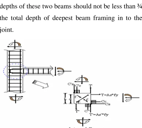
Exterior Joint:- An Exterior joint has at least two
beams framing into opposite sides of the joint. To
be classified as an exterior joint, the widths of the
beams on the two opposite faces of the joint should
cover at least ¾ the width of the column, and the
depths of these two beams should not be less than ¾
the total depth of deepest beam framing in to the
joint.
Fig 1.8 Exterior beam column joint
Corner Joint:- A Corner joint has at least one
beam framing into the side of the joint. To be
classified as a corner joint, the widths of the beam
on the face of the joint should cover at least ¾ the
width of the column.
Fig 1.9 Corner beam column joint
Volume2 Issue 2, Mar –Apr 2019 www.ijsred.com
Page 701 An Exterior joint has at least two
beams framing into opposite sides of the joint. To
be classified as an exterior joint, the widths of the
on the two opposite faces of the joint should
cover at least ¾ the width of the column, and the
depths of these two beams should not be less than ¾
the total depth of deepest beam framing in to the
Fig 1.8 Exterior beam column joint
A Corner joint has at least one
beam framing into the side of the joint. To be
classified as a corner joint, the widths of the beam
on the face of the joint should cover at least ¾ the
International Journal of Scientific Research and Engineering Development
©IJSRED: All Rights are Reserved Type1- Static loading Strength important, Ductility
secondary A type-1 joint connects members in an
ordinary structure designed on the basis of strength,
to resist the gravity and wind load.
Type2-Earthquake and blast loading Ductility +
strength, inelastic range of deformation, Stress
reversal A type-2 joint connects members designed
to have sustained strength under deformation
reversals into the inelastic range, such as members
designed for earthquake motions, very high wind
loads, or blast effects
Fig 1.10 Typical beam column joints
LOADING AND LOAD DEFLECTION
BEHAVIOUR
The exterior beam column joint specimen was
subjected to cyclic loading simulating earthquake
load. The load deflection behaviour of High
Strength concrete beam column joint,High
Performance Fibre Reinforced Concrete beam
International Journal of Scientific Research and Engineering Development-– Volume2 Issue 2, Mar Available at www.ijsred.com
©IJSRED: All Rights are Reserved loading Strength important, Ductility
1 joint connects members in an
ordinary structure designed on the basis of strength,
Earthquake and blast loading Ductility +
eformation, Stress
2 joint connects members designed
to have sustained strength under deformation
reversals into the inelastic range, such as members
designed for earthquake motions, very high wind
beam column joints
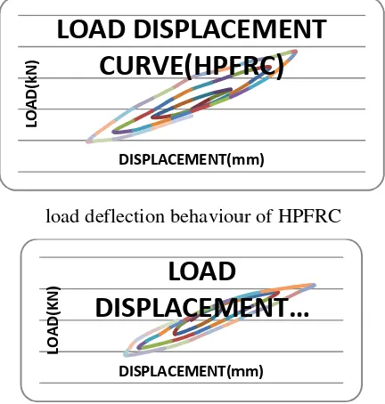
LOADING AND LOAD DEFLECTION
The exterior beam column joint specimen was
subjected to cyclic loading simulating earthquake
load. The load deflection behaviour of High
Strength concrete beam column joint,High
einforced Concrete beam
column joint and Modified spaced High
Performance beam column joint are shown in fig.
The beam column joint gradually loaded by
increasing the load level during each cycle the load
sequence consists of 1.5kN , 3kN, 4.5kN,etc… upto
failure load. The deflection are measured using dial
gauge for farward and reverse cycle of loading.
load deflection behaviour of high strength concrete
load deflection behaviour of HPFRC
load deflection behaviour of HPFRC modified
spacing
LO
A
D
(k
N
)
DISPLACEMENT(mm)
Load displacement
curve(HSC)
LO
A
D
(k
N
)
DISPLACEMENT(mm)
LOAD DISPLACEMENT
CURVE(HPFRC)
LO
A
D
(K
N
)
DISPLACEMENT(mm)
LOAD
DISPLACEMENT
Volume2 Issue 2, Mar –Apr 2019 www.ijsred.com
Page 702 column joint and Modified spaced High
Performance beam column joint are shown in fig.
The beam column joint gradually loaded by
increasing the load level during each cycle the load
sequence consists of 1.5kN , 3kN, 4.5kN,etc… upto
ailure load. The deflection are measured using dial
gauge for farward and reverse cycle of loading.
load deflection behaviour of high strength concrete
load deflection behaviour of HPFRC
load deflection behaviour of HPFRC modified
DISPLACEMENT(mm)
Load displacement
curve(HSC)
DISPLACEMENT(mm)
LOAD DISPLACEMENT
CURVE(HPFRC)
DISPLACEMENT(mm)
LOAD
International Journal of Scientific Research and Engineering Development-– Volume2 Issue 2, Mar –Apr 2019 Available at www.ijsred.com
ISSN : 2581-7175 ©IJSRED: All Rights are Reserved Page 703 DUCTILITY FACTOR AND CUMULATIVE
DUCTILITY FACTOR
Ductility may be broadly defined as the ability of a
structure to undergo inelastic deformations beyond
the initial yield deformation with no decrease in the
load resistance. A quantitative measure of ductility
has to be with reference to the bilinear load
deformation. The ration of ultimate deformation to
the yield deformation at the beginning of the
horizontal path of first yield can give a measure of
ductility. The ductility factor for various load cycle
of High Strength concrete beam column joint, High
Performance Fibre Reinforced Concrete beam
column joint and Modified spaced High
Performance beam column joint are shown in fig.
This is an important parameter to be considered for
earthquake resistant structures.
Cumulative ductility factor with Load Cycle for
HSC
Cumulative ductility factor with Load Cycle for HPFRC
Cumulative ductility factor with Load Cycle for
HPFRC
With modified spacing
CUMULATIVE ENERGY ABSORPTION
CAPACITY
When the beam column joint is subjected to cyclic
loading, such as those experienced during heavy
wind or earthquake, some energy is absorbed in
each load cycle. It is equal to the work in straining
or deforming the structure to the limit of deflection.
The relative energy absorption capacities during
various load cycles were calculated as the sum of
the areas under the hysteric loops from the load
deflection diagram.
The cumulative energy absorption capacity of the
beam column joint was obtained by adding the
energy absorption of the beam column joint during
each cycle considered and the values are plotted
and it is as shown in fig.
C u m u la ti v e D u ct il it y F a ct o r No.of cycles
Cumulative ductility …
C u m u la ti v e D u ct il it y F a ct o r No.of cycles
Cumulative ductility
factor Vs Load …
International Journal of Scientific Research and Engineering Development
©IJSRED: All Rights are Reserved Cumulative EnergyAbsorption Capacitywith Load
Cycle for HSC
STIFFNESS
Stiffness is the load required for causing unit
deformation of structural elements like beam
column joint. The procedure for calculating
Stiffness was as follows.,A tangent drawn for each
cycle of the hysteric curves at a load of P=0.78P
where Pu was the maximum load of that load cycle.
Determine the slope of the tangent drawn to eac
cycle, which gives the stiffness of that cycle.In
general, with the increase in the load there is
degradation of stiffness and that was shown in fig.
Stiffness Vs Load Cycles
C u m u la ti v e E n e rg y A b so rp ti o n C a p a ci ty (k N -m m ) No.of cycles
Cumulative Energy
Absorption Capacity
S ti ff n e ss (k N /m m ) Load cycleStiffness Vs Load
for war
Reve rse
International Journal of Scientific Research and Engineering Development-– Volume2 Issue 2, Mar Available at www.ijsred.com
©IJSRED: All Rights are Reserved Cumulative EnergyAbsorption Capacitywith Load
Stiffness is the load required for causing unit
ts like beam
column joint. The procedure for calculating
Stiffness was as follows.,A tangent drawn for each
cycle of the hysteric curves at a load of P=0.78Pu
was the maximum load of that load cycle.
Determine the slope of the tangent drawn to each
cycle, which gives the stiffness of that cycle.In
general, with the increase in the load there is
degradation of stiffness and that was shown in fig.
Stiffness Vs Load Cycles HSC
Stiffness Vs Load Cycles
Stiffness Vs Load Cycles
Cumulative Energy
Absorption Capacity…
Stiffness Vs Load …
Reve S ti ff n e ss (k N /m m ) Load cycle
Stiffness Vs Load
Cycles
for wa S ti ff n e ss (k N /m m ) Load cycleStiffness Vs Load Cycles
HPFRC
forwar d
Volume2 Issue 2, Mar –Apr 2019 www.ijsred.com
Page 704 Stiffness Vs Load Cycles HPFRC
Stiffness Vs Load Cycles HPFRC with m/s
Load cycle
Stiffness Vs Load
Cycles…
Reve rse
Load cycle
Stiffness Vs Load Cycles
HPFRC-MS
International Journal of Scientific Research and Engineering Development-– Volume2 Issue 2, Mar –Apr 2019 Available at www.ijsred.com
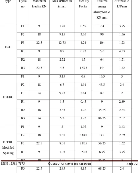
ISSN : 2581-7175 ©IJSRED: All Rights are Reserved Page 705 Table 1Experimental Results of Beam column
type Cycle
no
Maximum
load in KN
Max deflection
in mm
Ductility
Factor
Relative
energy
absorption in
KN-mm
Stiffness in
kN/mm
HSC
F1 9 1.78 0.59 7.4 3.75
F2 18 9.15 3.05 90 1.36
F3 22.5 12.73 4.24 104 1.23
R1 9 0.9 0.23 5.6 4.33
R2 18 2.72 1.5 64 1.71
R3 22.5 4.5 1.573 144 1.42
HPFRC
F1 9 3.15 0.9 10.5 3
F2 18 6.7 1.91 43.5 2.4
F3 24 9.23 2.64 87 2
R1 9 1.3 0.43 9 2.89
R2 18 3.65 1.22 35.25 2.34
R3 24 5.2 1.73 86.25 2.07
HPFRC
Modified
Spacing
F1 9 2 1.02 9 3.43
F2 18 5.65 3.845 33 2.69
F3 22.5 8.01 7.855 56.25 1.62
R1 9 1.05 0.525 6.75 3.75
R2 18 1.75 2 35.25 3
International Journal of Scientific Research and Engineering Development-– Volume2 Issue 2, Mar –Apr 2019 Available at www.ijsred.com
ISSN : 2581-7175 ©IJSRED: All Rights are Reserved Page 706 Table
2 Experimental Results of Beam column
CONCLUSION
The structural behaviour of 3 varieties of
exterior beam column joint are studied
experimentally. Experimental investigation shows
that the use of steel fibers arrests the crack and the
depth of the crack was found to be less. The
addition of steel fibers on concrete tends to increase
the load carrying capacity by about 7% while
comparing the HSC. While considering the other
parameter like ductility and stiffness degradation
use of steel fibre is recommended in the high
earthquake zone rather than increasing the grade of
concrete. The conclusion is arrived after studying
the properties of ductility, stiffness and energy
absorption parameters and more importantly the
failure pattern of the specimens.
REFERENCES
1. IS: 456-2000, “Plain and Reinforced
Concrete - Code of Practice”, Bureau of
Indian Standards, New Delhi.
2. Laura N. Lowes1 and Arash Altoontash, 12
may,2003 ”Modeling Reinforced-Concrete
Beam-Column Joints Subjected to Cyclic type Cycle no Cumulative Ductility
Factor
Cumulative Energy Absorption
in KN-mm
HSC
1 0.82 12.5
2 5.37 50
3 11.183 135
HPFRC
1 1.33 19.5
2 5.79 98.25
3 14.62 271.5
HPFRC
Modified Spacing
1 1.55 15.75
2 7.39 84
International Journal of Scientific Research and Engineering Development-– Volume2 Issue 2, Mar –Apr 2019 Available at www.ijsred.com
ISSN : 2581-7175 ©IJSRED: All Rights are Reserved Page 707 Loading” Journal Of Structural Engineering
ASCE
3. P.Rajaram, A.Murugesan and
G.S.Thirugnanam, 2010 “Experimental
Study on behavior of Interior RC Beam
Column Joints Subjected to Cyclic Loading”
international journal of applied engineering
research
4. S.R. Uma, Department of Civil Engineering,
University of Canterbury, March 16 2006,
New Zealand “Seismic design of
beam-column joints in RC moment resisting
frames – Review of codes” Structural
Engineering and Mechanics vol. 23, no.5,
pg.579- 597
5. S. Patil, S. S. Manekari April 2013
“ Analysis of Reinforced Beam-Column
Joint Subjected to Monotonic Loading”
International Journal of Engineering and
Innovative Technology (IJEIT) Volume 2,
Issue 10
6. Mehmet Unal , Burcu Burak, Civil
Engineering Department, Middle East
Technical University, K2-311 Ankara,
Turkey, 23 February 2013 “Development
and analytical erification of an inelastic
reinforced concrete joint model”
Engineering Structures vol.52,pg. 284–294
7. C. Geethajali, P. MuthuPriya and R.
Venkatasubramani “Behavior of HFRC
Exterior Beam Column Joints under Cyclic
loading”, International journal of science,
Engineering and Technology Research,
vol.3. May 2014.
8. K.R. Siva Chidambaram and G.S
Thirugnanam “Comparative Study on
Behaviour of Reinforced Beam-Column
Joints with Reference to Anchorage
Detailing”, Journal of civil engineering
Research, pp. 12- 17, 2012.
9. Ashish, B.U. and R.R.
Harshalata,Investigation on behaviour of
reinforced concrete beam column joints
retrofitted with FRP wrapping. Int. J. Civil
Eng. Res. 5 (3): 289–294 (2014). ISSN
2278-3652.
10.Bindhu, K.R. and K.P. Jayab, Strengthand
behaviour of exterior beam column joints
with diagonal cross bracing bars. Asian J.
Civil Eng. 11 (3): 397–410 (2010).
11.Chaudhari, S.V., K.A. Mukane andA.
Chakrabarti, Comparative study on exterior
RCC beam column joint subjected to
monotonic loading. Int. J. Comp. Appl. 102
(3): 34–39 (2014).
12.Ganesan, N., P.V. Indira and R. Abraham,
Steel fibre reinforced high performance
concrete beam-column joints subjected to
cyclic loading. ISET J. Earthquake Tech. 44
International Journal of Scientific Research and Engineering Development-– Volume2 Issue 2, Mar –Apr 2019 Available at www.ijsred.com
ISSN : 2581-7175 ©IJSRED: All Rights are Reserved Page 708 13.Ganesh Kumar, D. and S. Prabavathy,
Experimental study on seismic performance
in beam-column joint using hybrid fibers.
Int. J. Sci. Eng. Appl. 4 (3): 134–137 (2015).
ISSN-2319-7560.
14.Kalaivani, M. and S. Karthik, Steel fibre
reinforced concrete beam-column joint – A
review. Int. J. Eng. Res. Tech. 5 (05): 166–
173 (2016).
15.Kulkarni, S.M. and Y.D. Patil, Cyclic
behavior of exterior reinforced
beam-column joint with cross-inclined beam-column
bars. IOSR J. Mech. Civil Eng. 11 (4): 09–
17 (2014). e-ISSN: 2278-1684,P-ISSN:
2320-334X.
16.Mariselvam, T. and N. Sakthieswaran,
Experimental investigation on GFRP
wrapped R.C beam column joint. Int. J. Eng.
Res. 1 (1): 1–7(2015).
17.Muthupriya, P., S.C. Boobalan and B.G.
Vishnuram, Behaviour of fibre-reinforced
high-performance concrete in exterior
beam-column joint. Int. J. Adv. Struct. Eng.
6: 57 (2014).
18.Panjwani, P. and S.K. Dubey, Study of
reinforced concrete beam-column joint. Int.
J. Eng. Res. 4 (6): 321–324 (2015).
ISSN:2319-6890.
19.Patil, S.S. and S.S. Manekari, Analysis of
reinforced beam-column joint subjected to
monotonic loading. Int. J. Eng. Innov. Tech.
2 (10): 149–158 (2013).
20.Perumal, P. and B. Thanukumari, Seismic
performance of hybrid fibre
reinforced beam–column joint. Int. J.
Civil.Struct.Eng.1(4):749–774 (2010)
Doi:10.6088/ijcser.00202010063
21.Rajaram, P., A. Murugesan and G.S.
Thirugnanam, Experimental study on
behavior of interior RC beam column joints
subjected to cyclic loading. Int. J. Appl. Eng.
Res. 1 (1): 49–59 (2010).
22.Sharma, R.K. and H.K. Sharma, High
performance light weight aggregate fibrous
concrete beam-column joints: An state of art
overview. Int. J. Eng. Innov. Res. 5 (1):
114–121 (2016). ISSN: 2277 – 5668.
23.Subramani, T. and J. Jayalakshmi,
Analytical investigation of bonded glass
fibre reinforced polymer sheets with
reinforced concrete beam using Ansys. Int. J.
Appl. Innov. Eng Manage. 4 (5): 105–112
(2015).
24.Taucer, F.F., E. Spacone and F.C. Filippou,
A fiber beam-column element for seismic
response analysis of reinforced concrete
structures. Report No. UCB/EERC-91/17.
Unversity of California, Berkeley, CA
International Journal of Scientific Research and Engineering Development-– Volume2 Issue 2, Mar –Apr 2019 Available at www.ijsred.com
ISSN : 2581-7175 ©IJSRED: All Rights are Reserved Page 709 25.Vasagade, R.B. and D.N. Shinde, A study
on “Strength and Behavior of Exterior
Beam-Column Joint by using SCC and
SFRSCC.” Int. J. Sci. Res. Dev. 3 (12):
516–520 (2016). ISSN: 2321-0613.
26.Venkatesan, B., R. Ilangovan, P. Jayabalan,
N. Mahendran and N. Sakthieswaran, Finite
element analysis (fea) for the beam-column
joint subjected to cyclic loading was
performed using ANSYS. Circuits and