Compressive Sensing Based Channel Estimation for
High-order MIMO Systems
https://doi.org/10.3991/ijoe.v14i07.8218
Zhiguo Lv
Xidian University, Xi’an, China
Luoyang Institute of Science and Technology, Luoyang, China
Ying Li!!"
Xidian University, Xi’an, China
Abstract—The high-order multiple-input multiple-output (MIMO) system can remarkably increase the data rate or enhance the reliability. However, it is difficult to perform channel estimation because of the massive number of an-tennas. The Narrow Band Estimation Antenna Processing (NBEAP) scheme is used to deal with this issue. Nevertheless, the accuracy of the channel estima-tion needs to be improved. In this paper, a compressive sensing based scheme named Narrow Band Estimation Fixed Antenna Processing (NBEFAP) is pro-posed to estimate the channel state information (CSI) for high-order MIMO sys-tems. A simple pilot structure is designed to decrease the computation complex-ity. In addition, the pilot length is adjusted according to the time-varying sparsi-ty level of the CSI. Compared with NBEAP scheme, NBEFAP scheme can im-prove the estimation error performance. Simulation results verify the effective-ness of the NBEFAP scheme.
Keywords—Channel estimation, high-order MIMO, compressive sensing, CSI
1
Introduction
transmission efficiency. These observations motivate us to design a scheme which can estimate the CSI with shorter pilot sequences.
Recently, the compressive sensing (CS) [4-7] technique has been applied to recon-struct the sparse signal. In the CS theory, the high dimension sparse signal can be reconstructed by the low dimension measurement signal with high accuracy. On the other hand, recent experiments have shown that many wireless channels are either sparse or approximate sparse [8-10]. For some wireless channels which are not sparse, they can be represented as sparse virtual channels [11][12]. Therefore, the CS tech-nique exhibits great potentials in the field of channel estimation.
A channel feedback reduction techniques based on CS was proposed in [13]. How-ever, the attention was only paid to the CSI feedback from the receivers to the trans-mitters, rather than the estimation of the CSI. A low-rank matrix approximation based on CS was proposed to estimate the channel and solved via a quadratic semi-define programming in [14]. However, the estimation error performance of this scheme was not considered when the pilot sequence length is shorter than the number of the transmitting antennas. An adaptive one-bit compressed sensing scheme for channel estimation was proposed in [15], where the precoding and combining vectors are designed to increase the accuracy of the channel estimation depending on one-bit feedback from the receiver. Although the estimation accuracy is improved, the feed-back mechanism would result in reductions of the information transmission efficien-cy. A CS based channel estimation scheme was proposed in [16], where the CSI at the desired angle of arrival (AoA) and angle of departure (AoD) is obtained by selecting appropriate precoding and combining vectors. However, neither of the schemes in [15] and [16] has a detailed analysis of the measurement matrix which has a great influence on the channel estimation accuracy.
Bajwa, Sayeed and Nowak proposed another CS based scheme named narrow band estimation-antenna processing (NBEAP) [17]. In NBEAP scheme, a portion of trans-mitting antennas were chosen randomly to transmit the pilot signal , while the others keep silent. The estimation for the virtual sparse channel is performed by processing the pilot signals received on the randomly selected receiving antennas. However, the received signals are not fully exploited by this scheme. Besides, it is inconsistent with the actual situation to assume the channel sparsity level is priori known and time-invariant.
In this paper, a modified scheme named Narrow Band Estimation Fixed Antenna Processing (NBEFAP) is proposed. In the NBEFAP scheme, a simple pilot structure is designed to reduce the computational complexity. Moreover, the length of pilot sequence is adjusted flexibly according to the sparsity level of the channel. Simulation results verify that the NBEFAP scheme could guarantee the stability of the estimation error performance at different channel sparsity levels.
Notations: We use lower-case (upper-case) bold characters to denote vectors (ma-trixes). !!!! !!! denotes a Gaussian distribution with mean 0 and variance !!. !
! denotes an !!! identity matrix. In addition, !!!!, !!!! and !, denote transpose,
the (i, j)th entry of the matrix, [.]L the first L columns of a matrix and [.]Lth the Lth column of a matrix.
2
Channel models
Consider a high-order MIMO wireless communication system equipped with P transmitting antennas and Q receiving antennas, where P !!1 and Q !!1. There are !!"#! propagation paths in the physical channel. The gain of the nth path is denoted by n. The normalized angle of arrival and departure at the nth path are !!!! and !!!!
, respectively. They are given by
!!!! !!!"# !! !!!!!! (1)
!!!!!! !"#!!!!!!! (2)
where is the wavelength of propagation, d is the antenna spacing, !!!! and !!!! are physical AoA and AoD of the nth path , respectively. The corresponding response and steering vectors are !!!!!!!! and !!!!!!!! , respectively. They are given by
!! !!!! ! !! !! !!!!!!!!!! ! ! !!!!! !!! !!!! ! (3)
!! !!!! ! !!!!! !!!!!!!!!!! ! !!!!! !!! !!!!!!. (4)
As a result, the physical MIMO channel is modeled as
! ! !!!!"#!! !!!!!!!!!!!!!!!!!!!. (5) Generally, we uniformly quantify the physical propagation path into P virtual AoD and Q virtual AoA. The pth virtual AoD and qth virtual AoA correspond to a virtual direction matrix and a virtual path. The virtual direction matrix is given by
!!!! ! !! !!!! !!! !!!! . (6)
The gain of the virtual path is the superposition of the physical path gain around it. It is given by
!!!!!!!! !!!!!!!!!!!!!. (7)
!!!!!!! is the virtual path gain related to the qth virtual AoA and pth virtual AoD.
!!!! (resp. !!!!) denotes the set of paths whose physical AoA (resp. AoD) lies within the resolution bin centered around the qth (resp. pth) normalized virtual receive (resp. departure) angle !!"
!" (resp. !!"
!"). They are given by
!!!!! !!!!!!!! !!!"!" !!"! !!!"!" !!"!!}. (9)
Then, the physical channel matrix in (5) is calculated by summing all virtual direc-tion matrices multiplied by corresponding virtual path gain. It is written by
! ! !!" !!!!! !!!!!!!!!!!!!!!! (10)
where ! ! !!! !!!! and ! ! !! ! !!!!. Here, we set P and Q are odd. The repre-sentation of channel in (10) is decoupled as
! !!!!!!!!! (11)
where !! and !!! are discrete Fourier transform matrices which are written as
!!! !! !!! ! ! !!! !! (12)
!!! !! !!
! ! ! !!!
!
! . (13)
Each entry in !! represents the gain of the channel corresponding to a virtual path. The value of zero means that there is no propagation path between a pair of virtual AoA and AoD. When the number of nonzero entries in the matrix !! is very small compared to the total number of entries in !!, we call !! is sparse. The num-ber of the nonzero entries in !! is defined as the sparsity level of the channel which is denoted by k.
Based on the sparse virtual channel model, the task of channel estimation is per-formed by estimating the sparse matrix !!. In next section, we will introduce an NBEFAP scheme to estimate !!.
3
NBEFAP scheme
Our scheme mainly focuses on how to make channel estimation of high-order MIMO systems more efficient. The scheme is described below.
3.1 Pilot structure
The first !! transmitting antennas are selected to transmit the pilot signal in turn.
!! ! ! !! ! ! !! ! ! !! ! ! !! ! ! ! ! ! !! ! ! !! ! ! !! ! ! !! ! ! !
. (14)
Thus, the received pilot matrix Y is obtained as
!! !" ! ! ! !!!!!!!!! ! !! ! !!!! !!!! !!! !. (15)
Due to the special pilot structure, the result of multiplication !!! !
! is directly ob-tained by taking the first !!!columns of !!!
!. Therefore, the computational complexity
is decreased.
3.2 Processing of the received pilot signal
Depend on the received pilot signals on all receiving antennas, the virtual channel
!! is recovered. Since !! is a unitary matrix, !!!!!
!
! !!. Multiplying both sides of
equation (15) by matrix !!!
!, we obtain
!!! ! ! !!!!!!! ! !!!! !!! ! !. (16)
Then the channel estimation problem is written as
!!! !"#$%&!!!! !"#!!!! !"!!!!!!!!!!!!!!!!!!
!
! ! !!!!!!
!
!!!. (17)
When the nth transmitting antenna sends the pilot signal while the others keep si-lent, the received signal is
! !"!!!!!"!! !!"!! !!!!!!!!!!!"!! !!!!"!. (18)
Picking out the mth entry from !!"!, we have
! !!!! !!! !"!
!
!! !!!! !"!! !!!!!!!!!
!!!!!!!!!!!!!!!!!!!!!!! !!!!!!!!"!!!! !!! !"! !!"#!!!! ! !!!!!!. (19)
It is obvious that !!!!!! is related with all the entries of !!. Therefore, each entry of Y should be exploited to reconstruct !! .
When the pilot sequence length L satisfies the restricted condition ! !!!!"#!"! [18], the virtual channel !! is reconstructed as
!!!!"#$%&!!!! !"#!!!! !"!!!!!!!!!! !!!!!!"# !!!! ! !!"# !! (20)
where ! ! ! !!! !!"
!
!!!!! ! !!! !"! !
When the channel sparsity level k satisfies the restricted condition !!!"#!"! ! !, we reconstruct !! by one column of Y, i.e., the required pilot sequence length can be
as small as 1. In this case, the received pilot signal is expressed as
!!!!"!! !!"#!!!! ! !!!!"! (21)
where ! !!!!!!!!!"!!!!!!. According to equations (17) and (21), the channel
es-timation problem is simplified as
!!! !"#$%&!!!! !"#!!!! !"!!!!!!!!!! !!!!!!!!!"!! !!"#!!!!. (22)
3.3 Adjustment of the pilot sequence length
The sparsity level k is varied with time in practice. Hence, the transmitter adjusts the length of the pilot sequences according to the sparsity level of the channel to im-prove the transmission efficiency.
The channel estimation is performed once in a certain amount of information and pilot data which is called a data block. The pilot length is P in the first block. After obtaining the estimated virtual channel, the sparsity level and the required pilot length are computed at the receiver. Then, the required pilot length is fed back to the trans-mitter. In the second and subsequent blocks, the receiver performs the channel estima-tion and makes comparison between the current channel sparsity level and the previ-ous one. “0” is fed back to the transmitters if the sparsity level decreases. Otherwise, “1” is fed back. Accordingly, the transmitters would increase or reduce the pilot length by !! with feedback information “1” or “0”.
The Euclidean distance between the ideal constellation points and the received points increases with sparsity level. So the average Euclidean distance (AED) is used in practice instead of the sparsity level. The AED is written as
!!"#!
!!!! !! !! !
!!!!!!
! ! (23)
where ! denotes the computed constellation vector and ! denotes the ideal constella-tion vector, Y denotes the received pilot signal and ! denotes the estimated channel matrix. Since ! and ! have been calculated during the decoding of the information data. Therefore, the calculation of the AED is easy to perform.
4
Discussion of the NBEFAP scheme
In this section, we discuss the advantages of the proposed NBEFAP scheme. The computational complexities of different schemes are compared. The mutual coherence of the measurement matrix is also discussed since it has a great influence on the esti-mation accuracy.
4.1 Features of NBEFAP scheme
There are three features of our proposed NBEFAP scheme which is described be-low.
1.The fixed first !! antennas are chosen to transmit the pilot signal sequentially in
the proposed NBEFAP scheme. This design generates a simple pilot structure which decreases the calculation complexity in equation (15).
2.The received pilot signals on each receiving antenna have been fully utilized in the proposed NBEFAP scheme. This results in an accurate estimated channel.
3.The pilot sequence length is adjusted according to the sparsity level of !! to save
pilot resource. Compared with traditional schemes with fixed pilot sequence length, the proposed NBEFAP scheme improves the transmission efficiency.
4.2 Complexity analysis
For a high-order MIMO system equipped with P transmitting antennas and Q re-ceiving antennas, we use a L-length pilot sequence to estimate the channel with dif-ferent schemes.
The computational complexity of the proposed NBEFAP and conventional NBEAP scheme all mainly concentrate on the reconstruction of sparse channel. Sparse channel reconstruction can be implemented by
Matching Pursuit
(MP) orOrthogonal Matching Pursuit
(OMP) algorithm. The iterations is set to T when MP or OMP algorithm is employed. The computational complexity of theleast squares
(LS)
andlinear minimum mean square error (LMMSE)
algorithm are also given. The complexity comparison with different schemes is given in table 1. It shows that the proposed scheme has a larger complexity. This is a tradeoff between complexity and accuracy.4.3 Mutual coherence
The mutual coherence of a matrix M is defined as the maximum absolute value of the cross-correlations between columns of M. It is represented as
!!!! !!"#!!!!!!! !!!!!"!!
!!!!!"!
!!!!"! !! !!!!"!!!. (24)
The mutual coherence will take the minimum value of 0 when the columns in
M are mutually orthogonal. When there are two columns that are linearly related, the mutual coherence will take the maximum value of 1. According to [19], a smaller !!!! of the measurement matrix will bring a more accurate recovery of vec(!!). Usually it is required that the measurement matrix satisfies the mutual coherence property (MCP), i.e.,!! ! !!!! ! ! ! , here k is the sparsity level. Therefore, we need to analyze how to reduce the mutual coherence of the measurement ma-trix.
The domain of values of physical AoA is !!!!!!!!. It is symmetric with respect to origin. As a result, the domain of values of virtual AoA is !!!!!!" !!!!!"!. It is also symmetric with respect to origin. For !!! !! !!! ! ! !!! !! , the column vector
!! ! is the conjugation of another column !! !! . Besides, the !!!! th column in !! is !! ! . All the elements of !! ! are the same. Therefore, the measurement
matrix !! !!! !!" !
!!!! ! ! !!! !"! !
!!! has two columns that are
line-arly related. The mutual coherence will take the maximum value, i.e., !!!!=1. As a conclusion, the domain of AoA cannot be set to symmetry.
When the first column of ! is used alone as a pilot, the measurement matrix is written as ! ! !!! !!"
!
!!! . Since all the elements in !!!!!!!" are the same,
M will contain Q identical columns. As a result, !!!! = 1. So the first column of !
must not be used alone as a pilot.
Regardless of the pilot sequence length, the number of columns in M is QP. In-creasing the pilot length would only lead to a larger number of rows in M as well as a smaller cross-correlation between columns of M. Therefore, a long pilot sequence brings a small mutual coherence.
5
Simulation results
model parameters such as pilot sequence length, channel sparse levels and the number of antennas on channel estimation performance is given.
The accuracy of channel estimation is evaluated by the normalized mean squared error (MSE). It is calculated by
!!"#! !"!" !!!! !
!" (25)
where ! and ! are the estimated and actual channel matrix, Q and P represent the number of receiver and transmitter antennas, respectively. If no special statement, the model parameters used in this paper are listed as follows: transmitter antenna P=41, receiver antenna Q=61, AoA!! !!!!!!"!!"!, AoD! !!!!!!!!, sparsity level k=20 and antenna spacing d=0.5!.
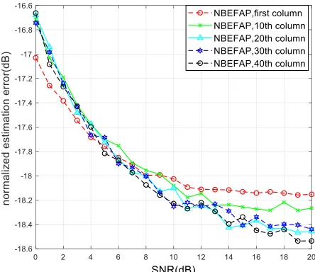
The MSE performance of the channel estimation with different columns of iden-tity matrix as pilot is given in Fig. 1. We can see that using the first column of ideniden-tity matrix as pilot leads to worse MSE performance than other columns at high Signal Noise Ratio (SNR). This is due to the fact that using the first column of identity ma-trix alone as pilot decreases the probability of measurement mama-trix satisfying the MCP.
Fig. 1. MSE performance of estimation with different pilot, k = 20, L = 1
The estimation MSE performance of NBEFAP scheme with different channel sparsity levels is given in Fig. 3. The simulation result shows that the estimation MSE performance is better when the sparsity level is small. When SNR = 10 dB, the MSE is about -52 dB in case of k = 5. Compared with the cases of k = 10 and 20, there are MSE performance gains of 15 dB and 25 dB, respectively.
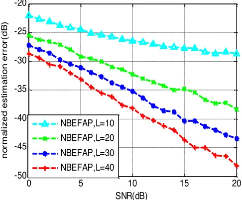
Fig. 2. MSE performance versus SNR with different pilot length, k=20
Fig. 3. MSE performance with different sparsity level, L=20
0 5 10 15 20
-50 -45 -40 -35 -30 -25 -20
SNR(dB)
no
rm
al
iz
ed
es
tim
at
ion er
ro
r(
dB
)
NBEFAP,L=10 NBEFAP,L=20 NBEFAP,L=30 NBEFAP,L=40
0 2 4 6 8 10 12 14 16 18 20
-65 -60 -55 -50 -45 -40 -35 -30 -25 -20
SNR(dB)
nor
m
al
iz
ed es
tim
at
ion er
ror
(dB
)
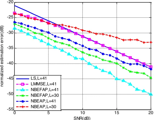
The estimation MSE performance comparison between the conventional NBEAP and the proposed NBEFAP scheme is given in Fig. 4. In NBEAP, 60 percent of the receiving antennas are randomly chosen. From the simulation result we get the fol-lowing conclusion. Using the same pilot length L=30, the NBEFAP scheme gets bet-ter MSE performance than the NBEAP scheme. The NBEFAP scheme still has betbet-ter estimation MSE performance even when its pilot length (L=30) is shorter than that of the NBEAP scheme (L=41). This is because that the whole received pilot data on each antenna is exploited to estimate the CSI in NBEFAP. The estimation MSE perfor-mance of LS and LMMSE algorithm are also given in Fig. 4. It shows that the NBEFAP scheme obtains better estimation MSE performance compared with the LS and LMMSE. Assuming that the user moves at the speed of 100km/h and the carrier frequency is 900MHz, the corresponding channel coherence time is about 5 ms. The periods of pilot and information data symbol are set as 0.07 ms. The transmission efficiency is 42.6% when the length of pilot sequence is 41. In contrast, if the length of pilot sequence is 30, the transmission efficiency can be increased to 58%.
Fig. 4. Comparison of the MSE performance between NBEFAP and NBEAP
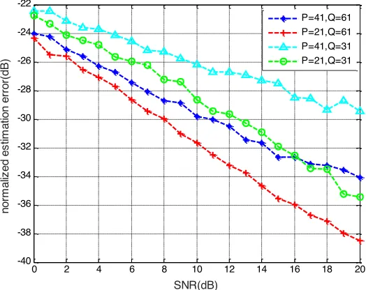
In Fig. 5, the MSE performance comparison with different numbers of antennas is given. It is observed that the MSE performance of the channel estimation is im-proved with the increase of the antennas. This is due to the fact that a large number of antennas provide great diversity gain.
For the case that the sparsity level of the channel changes slowly, the length of pilot sequence is adjusted adaptively according to the sparsity level. The channel estimation MSE performance is given in Fig. 6. We set the initial pilot length L=10,
!! =5 and SNR=5 dB. From the simulation result we find that the estimation MSE using fixed pilot length increases with the sparsity level. In contrast, the estimation
0 5 10 15 20
-55 -50 -45 -40 -35 -30 -25 -20
SNR(dB)
no
rm
al
iz
ed
es
tim
at
ion er
ro
r(
dB
)
MSE using adaptive varying pilot length is almost constant, regardless of the sparsity level. It is important to maintain the stability of channel estimation accuracy in high-order MIMO system. Since there is no need to frequently adjust parameters such as transmission power according to the channel estimation accuracy, the complexity of the transmission is reduced.
Fig. 5. Comparison of the MSE performance with different numbers of antennas
0 2 4 6 8 10 12 14 16 18 20
-40 -38 -36 -34 -32 -30 -28 -26 -24 -22
SNR(dB)
nor
m
aliz
ed es
tim
at
ion er
ror
(dB
)
P=41,Q=61 P=21,Q=61 P=41,Q=31 P=21,Q=31
10 11 12 13 14 15 16 17 18 19 20
-44 -42 -40 -38 -36 -34 -32 -30 -28 -26 -24
spaarsity level
nor
m
al
iz
ed es
tim
at
ion er
ror
(dB
)
L=10 L=20 L=30
6
Conclusions
In this paper, we propose a CS based scheme for channel estimation in high-order MIMO system. An accurate channel estimation is obtained with short pilot sequence. The key idea of the scheme is using a partition of an identity matrix as pilot matrix and estimating the CSI with CS theory. Since the pilot matrix has simple structure, the complexity of channel estimation is reduced. The received pilot signals on each re-ceiving antenna have been fully utilized which results in an accurate estimated chan-nel. When the sparsity level of the channel varies with time, the length of pilot se-quence is adjusted dynamically to save pilot resources. Another benefit of the varying pilot length is that the channel estimation MSE performance keeps almost constant as the sparsity level increases. The simulation results validate the effectiveness of the NBEFAP scheme.
7
Acknowledgment
This work was supported by the national Natural Science Foundation of China un-der grant 61671345 and the Joint Fund of Ministry of Education of China (No.6141A02022338).
8
References
[1]Mehmood.Y., Afzal, W., Ahmad, F., Younas, U., Rashid, I., Mehmood, I. (2013). Large scaled multi-user MIMO system so called massive MIMO systems for future wireless communication networks, Automation and Computing (ICAC), 2013, London, UK, pp.1-4 [2]E. G. Larsson, F. Tufvesson, O. Edfors, and T. L. Marzetta. (2014). Massive MIMO for
next generation wireless systems. IEEE Commun. Mag. 52: 186-195 https://doi.org/10.1109/MCOM.2014.6736761
[3]F. Rusek et al. (2013). Scaling Up MIMO: Opportunities and Challenges with Very Large Arrays, IEEE Sig. Proc. Mag. 30: 40-60 https://doi.org/10.1109/MSP.2011.2178495 [4]D. Donoho. (2006). Compressed Sensing, IEEE Transactions on Information Theory,
52:1289-1306 https://doi.org/10.1109/TIT.2006.871582
[5]W. Ding, Y. Lu, F. Yang, et al. (2016). Spectrally Efficient CSI Acquisition for Power Line Communications: A Bayesian Compressive Sensing Perspective, IEEE Journal on Se-lected Areas in Communications, 34: 2022-2032 https://doi.org/10.1109/JSAC. 2016.2566140
[6]W. Ding, F. Yang, C. Pan, et al. (2014). Compressive Sensing Based Channel Estimation for OFDM Systems Under Long Delay Channels, IEEE Transactions on Broadcasting, 60: 313-321 https://doi.org/10.1109/TBC.2014.2315913
[7]G. Jie, B. Song, Y. He, et al. (2017). A Survey on Compressed Sensing in Vehicular Info-tainment Systems, IEEE Communications Surveys and Tutorials, 19: 2662–2680 https://doi.org/10.1109/COMST.2017.2705027
[9]Z. Yan, M. Herdin, A. M. Sayeed, et al. (2007). Experimental study of MIMO channel sta-tistics and capacity via the virtual channel representation, Tech. Rep., Univ. Winsconsin-Madison, http://dune.ece.wisc.edu/pdfs/zhou meas.pdf
[10] G. Gui, N. Liu, L. Xu and F. Adachi. (2015). Low-complexity large-scale multiple-input multiple-output channel estimation using affine combination of sparse least mean square filters, IET Communications, 9:2168-2175 https://doi.org/10.1049/iet-com.2014.0979 [11]A. M. Sayeed. (2002). Deconstructing multiantenna fading channels, IEEE Transactions
on, Signal Processing, 50:2563-2579 https://doi.org/10.1109/TSP.2002.803324
[12]A. M. Sayeed. (2003). A virtual representation for time- and frequency-selective correlated MIMO channels, Acoustics, Speech, and Signal Processing, 2003. Proceedings. (ICASSP '03). Hong Kong, China, 4: 648-651
[13]Ping-Heng Kuo, Kung, H.T, Pang-An Ting. (2012). Compressive sensing based channel feedback protocols for spatially-correlated massive antenna arrays, Wireless Communica-tions and Networking Conference (WCNC), Shanghai, China, pp.492-497 https://doi.org/10.1109/WCNC.2012.6214417
[14]S. Nguyen and A. Ghrayeb. (2013). Compressive sensing-based channel estimation for massive multiuser MIMO systems, IEEE Wireless Communications and Networking Con-ference (WCNC), Shanghai, China, pp.2890-2895.
[15]C. Rusu, R. Mendez-Rial, N. Gonzalez-Prelcic and R. W. Heath. (2015). Adaptive One-Bit Compressive Sensing with Application to Low-Precision Receivers at mmWave, IEEE Global Communications Conference (GLOBECOM), San Diego, CA, pp. 1-6. https://doi.org/10.1109/GLOCOM.2015.7417853
[16]R. Méndez-Rial, C. Rusu, A. Alkhateeb, N. González-Prelcic and R. W. Heath. (2015). Channel estimation and hybrid combining for mmWave: Phase shifters or switches?, In-formation Theory and Applications Workshop (ITA), San Diego, CA, pp. 90-97. https://doi.org/10.1109/ITA.2015.7308971
[17]Bajwa, W.U.; Sayeed, A.; Nowak, R. (2008). Compressed sensing of wireless channels in time, frequency, and space, 42nd Asilomar Conference. Signals, Systems and Computers, Pacific Grove, CA, USA, pp.2048-2052
[18]E. J. Candes and T. Tao. (2005). Decoding by linear programming, IEEE Trans. Inf. Theo-ry, 51: 4203-4215 https://doi.org/10.1109/TIT.2005.858979
[19]M. F. Duarte and Y. C. Eldar. (2011). Structured compressed sensing: From theory to ap-plications, IEEE Trans. Signal Processing, 59:4053-4085 https://doi.org/10.1109/TSP.20 11.2161982
9
Authors
Zhiguo Lv received the B.S. degree in applied electronic technology from Henan Normal University, Xinxiang, China, in 2000, the M.S. degree in communications engineering from Guilin University of Electronic Technology, Guilin, China, in 2008. Since 2008, he has been on the faculty of Luoyang Institute of Science and Technolo-gy. He is currently working toward the Ph.D. degree at Xidian University. His re-search interests include MIMO communication and compressive sensing. (E-mail: [email protected])
ty of California, Davis, USA, as a Visiting Scholar. She is currently a Professor with Xidian University. Her current research interests are on design and analysis for wire-less systems, including channel coding, wirewire-less network communications, interfer-ence processing, and MIMO techniques.