Performance Analysis and Parametric Variation
of a Solar Adsorption Chiller
Parash Goyal Prashant Baredar
Student Associate Professor
Energy Centre Energy Centre
Maulana Azad National Institute of Technology, Bhopal, India Maulana Azad National Institute of Technology, Bhopal, India
Arvind Mittal
Associate Professor Energy Centre
Maulana Azad National Institute of Technology, Bhopal, India
Abstract
Solar energy is the most promising among the available green energy sources and also the panacea to the increasing global warming potential and ozone depletion. In the last three decades, various technologies have been invented for extracting the latent potential of the solar energy. Among them, the one that is still unearthed and needs to be researched is the adsorption refrigeration cycle. In the present paper, we have designed a basic adsorption chiller driven by solar thermal energy which consists of a solar collector, an adsorbent bed, a condenser and an evaporator. The model provides a maximum COP of 0.452 with a refrigeration power of 6.78 kW. Moreover, we have provided the variation of COP system and COP cycle with time. Here, we have also inferred the response of COP with variation in mass and collector area and we came to the conclusion that the COP of the present system declines if the mass exceeds 15 Kg.
Keywords: Solar Adsorption Chiller, Solar Refrigeration, Parametric Variation, Cop, Solar Collector
_______________________________________________________________________________________________________
I.
I
NTRODUCTIONGlobal warming, change in the seasonal cycle, limitation of primary energy compared to the need of the growing global population, are the prime concern of the twenty first century. Cooling and refrigeration are essentials for modern day’s society to provide the human comfort. In tropical countries like India, which experience extreme in the mainland, demand for electricity shoots up due to the need for cooling. The high electricity demand not only overloads the grid but harms the environment as well due to the burning of fossil fuels, which are the primary source of power. Most of the technologies at present for providing cooling or refrigeration are vapor compressor technology. However, the vapor compressor refrigeration device is one of the technologies responsible for ozone layer destruction as most of these use HCFCs and HFCs. Solar energy for cooling applications provides an opportunity to overcome this problem. The amount of solar radiation intercepted by the Earth’s surface is much higher than the annual global energy use. The energy available from the sun (82x1015 Wp) is greater than about 5200
times the global world’s need in 2006 [1]. In recent years, many promising technologies have been developed to harness the Sun’s energy. These technologies help in environmental protection, economizing energy, and sustainable developments which are the major issues of the world in the 21st century. The fact that cooling demand in summer is proportional to the availability of solar energy has been spurring the researchers to further exploit solar energy.
In cooling applications, different types of sorption systems can be employed. Among them one is the adsorption cycles. Adsorption refrigeration is a thermal driven refrigeration system, which can be powered by solar energy as well as waste heat [2]. The use of thermal driven systems helps to reduce the carbon dioxide emission from combustion of fossil fuels in power plants. Another advantage for adsorption systems compared with conventional vapor compression systems is the working fluid used. Adsorption systems mainly use a natural working fluid such as water and ammonia, which have zero ozone depletion potential.
until the adsorption conditions are established then the valve between the evaporator and the adsorbed is reopened. In the present study, we have designed, fabricated and tested a single stage adsorption chiller.
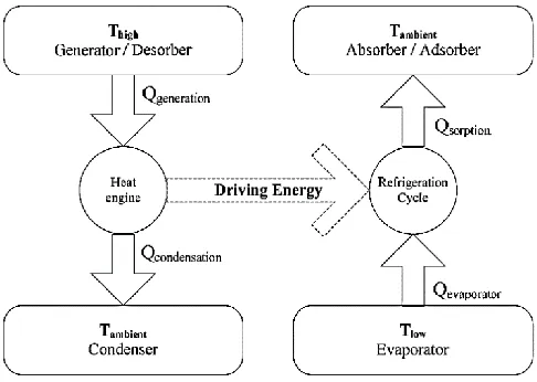
Fig. 1: Principle of basic adsorption cycle
II.
P
REVIOUS WORKSThe sorption refrigeration driven by solar energy attracted broad attention because the heat supply and cool demand are very well matched with the season and the heat quantity. Compared with the absorption system, the adsorption system that are driven by the heat sources of lower temperatures makes the application of solar energy more feasible on the adsorption system.
The solid adsorption refrigeration technology driven by solar energy has been researched extensively since Tchernev [4] successfully developed the refrigeration system with zeolite– water as the working pair. Pons and Guilleminot in France, studied activated carbon–methanol and zeolite–water adsorption systems driven by solar energy, in which the COP of the activated carbon–methanol ice maker [5] is 0.12–0.14 with a collector area of 6m2 (four collectors) and adsorbent mass of 20–24 kg/m2, and the COP of a zeolite–water refrigerator [6] is about 0.10 with the collector area of 20m2 (24 collectors) and the adsorbent mass of 360 kg. K. Sumathy et al. investigated an activated carbon–methanol ice maker powered by solar energy, and results showed that the daily ice production is 4–5 kg and the COP is 0.1–0.2 [7] when the area of flat plate collector is 0.92m2. Y.K. Tan [8-10] in South China University of Technology and Z.F. Li et al. in Guangzhou Institute of Energy Conversion [11] also developed the solid adsorption refrigeration system driven by solar energy, which had a similar performance to the system developed by K. Sumathy. Different from the refrigeration system with the integrated solar collector–adsorption generator, multi types of solar energy powered adsorption refrigeration systems were developed. Iloeje et al. [12, 13] utilized a tubular type of absorber, for which the adsorbent (such as calcium chloride, activated carbon) is filled inside the metal pipes. The concentric tube arranged at the center of the metal pipe served as the mass transfer channel of the refrigerant, and the metal tube is boned on the collector surface. Erhard [14] arranged the condensation part of the horizontal heat pipe inside the adsorbent bed to improve the heat flux density. Headley et al. [15] studied the activated carbon–methanol adsorption refrigerating system utilizing the compound parabolic concentrator (CPC) as the heat source. The system could realize refrigeration even if the solar radiation is very feeble, but the efficiency of the refrigeration system is very low. Bansal et al. [16] studied the SrCl2-NH3 adsorption
refrigerating system driven by the vacuum tube type collector. Vasiliev [17] developed a continuous adsorption heat pump with heat recovery process driven by solar energy and natural gas, using a parabolic concentrator for collecting the solar energy to heat the circulating water. The system employed solar energy as a main power supply, and the natural gas served as an auxiliary heat source when solar energy is not enough. The system can accomplish continuous refrigeration with the cycle time of 12 minutes Z.Y. Liu [18, 19] put forward the refrigeration system which combined the unit adsorption tube with the collector for the solar energy. For such a design the adsorbent bed can be heated by solar energy directly.
On the topic of solar energy utilization, SJTU [20] developed a compound system of water heater and refrigerator driven by solar energy to improve energy efficiency. Meanwhile, SJTU also developed the silica gel–water adsorption chiller in 2004, which had been applied to the building and grain storage hall with solar energy as the driving power.
III.
B
ASIC ADSORPTION REFRIGERATION SYSTEMis packed in a hermetically sealed container painted black for solar radiation absorption at a particular temperature in compliance with its condensing pressure.
A basic adsorption cycle consists of four thermodynamic steps.
Heating and Pressurization A.
The adsorber receives heat while being closed. The adsorbent temperature increases, which increases pressure from the evaporation pressure to the condensation pressure. This process is equivalent to the "compression" in compression cycles. Refer line AB in fig.2.
Heating, Desorption and Condensation B.
The adsorber continues receiving heat while being connected to the condenser. The adsorbent temperature continues increasing, which induces desorption of vapor. This desorbed vapor gets liquefied in the condenser. This is equivalent to the "condensation" in compression cycles. Refer line BC in fig. 2.
Cooling and Depressurization C.
During this period, low pressure vapor is entered to adsorber from evaporator. The adsorber releases heat while being closed. The adsorbent temperature decreases, which decrease pressure from the condensation pressure down to the evaporation pressure. This process is equivalent to the "expansion" in compression cycles. Refer line CD in fig. 2.
Cooling, Adsorption and Evaporation D.
The adsorber continues releasing heat while being connected to the evaporator. The adsorbent temperature continues decreasing, which induces adsorption of vapor. This adsorbed vapor is vaporized in the evaporator. The evaporation heat is supplied by the heat source at low temperature. This is equivalent to the "evaporation" in compression cycles. Refer line DA in fig. 2.
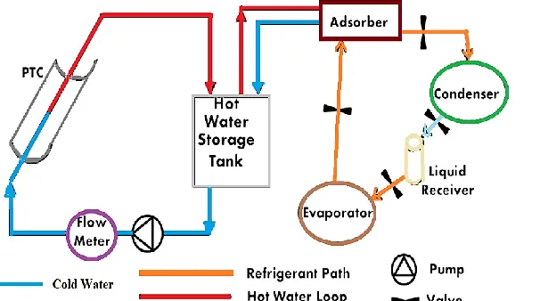
The schematic of the adsorption chiller is shown in fig. 3. In the present case we have fabricated the adsorption chiller following the schematics shown. We have used activated carbon and methanol as the working pair.
Fig. 2: Clayperon curve of basic adsorption refrigeration cycle.
IV.
P
ERFORMANCE PARAMETERSFrom the Clapeyron diagram, the total energy gained by the system during the heating period QT will be the sum of the energy
QAB used to raise the temperature of the A.C+ methanol from point A to B and the energy QBD used for progressive heating of the A.C to point D and desorption of methanol.
QT = QAB + QB
QAB = (mA:C CpA:C +CpmmmA)(TB -TA )
QBD = [mA:C CpA:C + Cpm{ (mmA + mmD)/ 2}](TD – TB)+ (mmA - mmD)H
The gross heat released during the cooling period Qe1 will be the energy of vaporization of methanol. Qe = (mmA - mmD) L
But the net energy actually used to produce ice Qe will be Qe = Qe1 – Qe2,
where Qe2 is the energy necessary for cooling the liquid adsorbate from the temperature at which it is condensed to the
temperature at which it evaporates. Qe2 = (mmA - mmD) Cpm (Tc - Te)
Qice1 is the energy required to cool water from TA to 0oC and to produce ice
Qice1 = M* (L* Cpwater (TA - 0)),
where M* and L* are the mass and latent heat of fusion of ice and net cooling produced will be Qice = M * L*
1) The collector efficiency Ƞ1=QT/ QI ,
where QI is the total solar energy input to the system during the day.
2) The cycle COP = Qe1/QT
3) The net solar COP net = Qice / QI
Here, Cp is specific heat in kJ/kgK, H is heat of desorption in kJ/kg, L is latent heat of evaporation of the methanol in kJ/kg, M is mass in kg, Q is energy in kJ, T is temperature in ºC.
V.
P
ERFORMANCE ANALYSISFig. 4 shows the variation of the solar incident radiation and the ambient atmospheric temperature with the day hours. These data simulate a summer day in May 5, 2015, for Bhopal, India.
Fig. 4: Variation of Solar radiation and ambient temperature with time
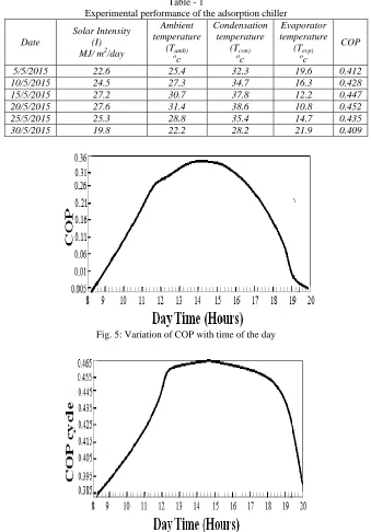
Table 1 shows the experimental results obtained from the experiments performed on the basic adsorption system. It shows the per day solar intensity, average ambient temperature corresponding to the respective solar radiation intensity, condensation temperature, evaporator temperature and the coefficient of performance (COP). It shows that as the ambient temperature increases i.e. increase in solar radiation intensity, there is an increase in the condensation temperature along with a more reduction in evaporation temperature. From the results in table it is evident that there exists a relation among the COP, Tcon and
Tevp. The system possesses a monthly average COP of 0.4305 calculated for the month of May.
Table - 1
Experimental performance of the adsorption chiller
Date
Solar Intensity (I) MJ/ m2/day
Ambient temperature
(Tamb) o
c
Condensation temperature
(Tcon) o
c
Evaporator temperature
(Tevp) o
c
COP
5/5/2015 22.6 25.4 32.3 19.6 0.412
10/5/2015 24.5 27.3 34.7 16.3 0.428
15/5/2015 27.2 30.7 37.8 12.2 0.447
20/5/2015 27.6 31.4 38.6 10.8 0.452
25/5/2015 25.3 28.8 35.4 14.7 0.435
30/5/2015 19.8 22.2 28.2 21.9 0.409
Fig. 5: Variation of COP with time of the day
Fig. 6: Variation of COPcycle with time of the day
Fig. 7: Response surface of the COP of refrigerator as a function of mass and collector area
VI.
C
ONCLUSIONSAdsorption cooling systems have received significant interest during the last few decades in order to satisfy the market demand of cooling systems and cope with the current environmental issues. In the present study we excogitated, fabricated and tested a solar adsorption refrigerator which uses activated carbon and methanol as the working pair. This system was tested for the meteorological conditions of MANIT, Bhopal. Maximum COP and refrigeration power of the modelled chiller was calculated to be 0.452 that occurred on 20th of May and 6.78 kW respectively. From the experiments performed we can conclude that on a particular day COP follows a parabolic curve which attains its peak near 13:00 hrs. Also we can conclude that COPcycle follows
an approx. constant curve for a duration of 5 hours. The maximum value of COPcycle s 0.465. Moreover, we can infer that if the
collector area is increased then the COP would increase but simultaneously we have to maintain the generating temperature as if it crosses the optimum generating temperature the COP value will start declining. It is found that the present model is capable of operating only in night time with fairly good performance. Hence this system suffers from intermittency i.e. not capable of providing cooling for the 24 hours of the day. Hence, for this generally two stage adsorption systems are employed in order to overcome the intermittent nature.
R
EFERENCES[1] Habib K, Saha BB, Chakraborty A, Oh ST, Koyama S. (2013) Study on solar driven combined adsorption refrigeration cycles in tropical climate. Applied
Thermal Engineering; 50(2): 1582–1589 http://dx.doi.org/10.1016/j.applthermaleng.2011. 11.042.
[2] Sumathy K, Yeung KH, Yong L. (2003) Technology development in the solar adsorption refrigeration systems. Prog Energy Combust Sci; 29 (4): 301–27,
http://dx.doi.org/10.1016/S0360-1285(03)00028-5.
[3] Dieng AO, Wang RZ. (2001) Literature review on solar adsorption technologies for ice-making and air conditioning purposes and recent developments in
solar technology. Renew Sustain Energy Rev; 5(4):313–42, http://dx.doi.org/ 10.1016/S1364-0321(01)00004-1.
[4] Tchernev, D. (1985) Heat pump energized by low-grade heat sources. US Patent PCT/US85/00783.
[5] Pons, M. and Guilleminot, J.J. (1986) Design of an experimental solar-powered, solid-adsorption ice maker. ASME Journal of Solar Energy Engineering,
108, 332–337.
[6] Grenier, P., Guilleminot, J.J. and Meunier, F. (1988) Solar powered solid adsorption cold store. Solar Energy Engineering, 110, 192–197.
[7] Sumathy, K. and Li, Z.F. (1999) Experiments with solar-powered adsorption ice maker. Renewable Energy, 16, 704–707.
[8] Feng, Y. and Tan, Y.K. (1990). The experimental research on the adsorption refrigeration for the recovery of the waste heat in industries. Energy Conservation Technology, (4), 1–3, ISSN: 1002–6339 (in Chinese).
[9] Feng, Y. and Tan, Y.K. (1990). The research for the adsorption refrigeration cycle with activated carbon-methanol as the working pair. Journal of Refrigeration, (1), 1–5, ISSN: 0253–4339 (in Chinese).
[10] Feng, Y. and Tan, Y.K. (1991) Research on the heat and mass transfer performance for the adsorption refrigeration systems. Journal of Chemical Industry
and Engineering, 42(3), 342–347, ISSN: 0438-1157 (in Chinese).
[11] Li, Z.F., Huang, Z.C. and Liu, G.X. (1991). The principle and experimental research on the solid adsorption refrigeration powered by the solar energy. Journal of Refrigeration, 1, 21–26, ISSN: 0253-4339 (in Chinese).
[12] Enibe, S.O. and Iloeje, O.C. (1997) Design optimization of the flat plate collector for a solid absorption solar refrigerator. Solar Energy, 60(2), 77–87.
[13] Enibe, S.O. and Iloeje, O.C. (1997) Transient analysis and performance prediction of a solid absorption solar refrigerator. Solar Energy, 60(1), 43–59.
[14] Erhard, D., Spindler, K. and Hahne, E. (1998) Test and simulation of a solar powered solid sorption cooling machine. International Journal of Refrigeration,
21(2), 133–141.
[15] Headley, S., Kothdiwal, A.F., McDoom, I.A. et al. (1994) Charcoal-methanol adsorption refrigerator powered by a compound parabolic concentrating solar
collector. Solar Energy, 53(2), 191–197.
[16] Bansal, N.K., Blumenberg, J., Kavasch, H.J. et al. (1997) Performance testing and evaluation of solid absorption solar cooling unit. Solar Energy, 61(2),
127–140.
[17] Vasiliev, L.L. (2005) Heat pipes in modern heat exchangers. Applied Thermal Engineering, 25(1), 1–19.
[18] Liu, Z.Y., Lu, Y.Z. and Zhao, J.X. (1998) Zeolite-active carbon compound adsorbent and its use in adsorption solar cooling tube. Solar Energy Materials
and Solar Cells, 52, 45–53.
[19] Liu, Z.Y., Lu, Y.Z. and Wang, Y.T. (2000) Experimental research on a novel solar powered refrigerating pipe. Acta Energiae Solaris Sinica, 21(1), 82–88,
ISSN: 0254-0096 (in Chinese).