7 Advances in Science and Technology
Research Journal
Volume 9, No. 26, June 2015, pages 7–11
DOI: 10.12913/22998624/2358 Research Article
Received: 2015.04.02 Accepted: 2015.05.08 Published: 2015.06.01
STACKING SEQUENCE OPTIMIZATION OF COMPOSITE BEAMS WITH
DIFFERENT LAYER THICKNESSES
Fatih Karaçam1, Taner Timarci1
1 Department of Mechanical Engineering, Faculty of Engineering, Trakya University, Edirne 22030, Turkey, e-mail: [email protected]; [email protected]
ABSTRACT
In this study, stacking sequence optimization of composite beams with different layer thicknesses is investigated for various boundary conditions. A unified shear deformation theory is used for analytical solution. The optimization process is carried out in order to obtain the minimum deflection parameters for Clamped-Free (C-F), Clamped-Clamped (C-C) and simply supported (S-S) boundary conditions under a uniform distributed load by use of genetic algorithm for a specific number of population and generation. Finally, among all possible combinations of layer thicknesses, the one giving the minimum de-flection parameter and corresponding stacking sequence is chosen. The minimum values and corresponding stacking sequences are presented for different boundary conditions.
Keywords: laminated composite beams, static analysis, genetic algorithm, layer thickness, stacking sequence optimization.
INTRODUCTION
Composite materials have gained popularity in modern structures where light-weight and high strength are sufficient to carry various loading types for different boundary conditions. Because of high elasticity modulus and strength, compos-ite materials are more popular than any conven-tional materials, besides, the advantage of being designed with many parameters such as stacking sequence, layer thicknesses, material and geo-metrical properties, structures can be designed effectively in order to satisfy the desired mechani-cal properties. Walker and Smith [1] studied the
ending analysis of laminated composite plates by minimizing a certain fitness function with ge-netic algorithm (GA). Due to the manufacturing constraints, they chose the sets of values from the ply angles and layer thicknesses. Conti et al. [2] described a method to optimize the thickness balance within a composite laminate with layers oriented according to a limited set of angles and used a finite element method in optimization
pro-cess. Lee et al. [3], used a parallel evolutionary
Advances in Science and Technology Research Journal Vol. 9 (26) 2015
8
combinations of layer thicknesses, the one that has the minimum deflection parameter and corre-sponding stacking sequence is presented.
ANALYTICAL METHOD
In the study, the beam is assumed to be con-structed of four linearly elastic layers. Various boundary conditions are applied to the beam under the effect of a uniform distributed transverse load. The beam has a unith width, length of L and thick-ness of h in a typical coordinate system where 0 ≤ x
≤ L and –h/2 ≤ z ≤ h/2 as shown in Figure 1.
Fig. 1. Beam geometry and coordinate system
Uniform shear deformation beam theory is used in the static analysis where the other beam theories can be obtained as a special case [6]. The displacement fields are given by:
In the study, the beam is assumed to be constructed of four linearly elastic layers. Various boundary conditions are applied to the beam under the effect of a uniform distributed transverse load. The beam has a unith width, length of 𝐿𝐿 and thickness of ℎ in a typical coordinate system where 0 ≤ 𝑥𝑥 ≤ 𝐿𝐿 and −ℎ/2 ≤ 𝑧𝑧 ≤ ℎ/2 as shown in Figure 1.
Fig. 1. Beam geometry and coordinate system.
Uniform shear deformation beam theory is used in the static analysis where the other beam theories can be obtained as a special case [6]. The displacement fields are given by
𝑈𝑈(𝑥𝑥, 𝑧𝑧) = 𝑢𝑢(𝑥𝑥) − 𝑧𝑧 𝑤𝑤(𝑥𝑥),𝑥𝑥+ ∅(𝑧𝑧) 𝑢𝑢1(𝑥𝑥) (1)
𝑊𝑊(𝑥𝑥, 𝑧𝑧) = 𝑤𝑤(𝑥𝑥)
where 𝑈𝑈, 𝑊𝑊 are the displacement fields of the beam and 𝑢𝑢, 𝑢𝑢1, 𝑤𝑤 are the displacement fields of
the mid-plane. ∅(𝑧𝑧) represents the shape function that varies depending on the beam theory chosen [7]. By use of the stress-strain relations into force (𝑁𝑁𝑥𝑥) and moment definitions (𝑀𝑀𝑥𝑥,
𝑀𝑀𝑥𝑥𝑎𝑎), the constitutive equations are given as below:
[𝑀𝑀𝑁𝑁𝑥𝑥𝑥𝑥
𝑀𝑀𝑥𝑥𝑎𝑎
] = [𝐴𝐴𝐵𝐵1111 𝐵𝐵𝐷𝐷1111 𝐵𝐵𝐷𝐷111111
𝐵𝐵111 𝐷𝐷111 𝐷𝐷1111
] [ 𝑢𝑢,𝑥𝑥
−𝑤𝑤,𝑥𝑥𝑥𝑥
𝑢𝑢1,𝑥𝑥
] , 𝑄𝑄𝑥𝑥𝑎𝑎= 𝐴𝐴55 𝑢𝑢1 (2)
where 𝐴𝐴𝑖𝑖𝑖𝑖, 𝐵𝐵𝑖𝑖𝑖𝑖 and 𝐷𝐷𝑖𝑖𝑖𝑖 denote the extensional, coupling and bending rigidities and 𝑄𝑄𝑥𝑥𝑎𝑎 denotes
the shear force respectively. The rigidities with more than two indices and the moment with superscript 𝑎𝑎 correspond to the shear deformation beam theory and subscript comma indicates the derivation with respect to the relevant axis. The governing equations of composite beam for static analysis under the effect of a uniform distributed load are given as follows:
𝑁𝑁𝑥𝑥,𝑥𝑥 = 0
(3) 𝑀𝑀 𝑥𝑥,𝑥𝑥𝑥𝑥 = 𝑞𝑞(𝑥𝑥)
𝑀𝑀𝑥𝑥,𝑥𝑥𝑎𝑎 − 𝑄𝑄𝑥𝑥𝑎𝑎= 0
The boundary conditions are prescribed at the edges of the beam when 𝑥𝑥 = 0 and 𝐿𝐿 and are given for simply supported, cantilever and free cases respectively as follows:
𝑁𝑁𝑥𝑥,𝑥𝑥 = 𝑤𝑤 = 𝑀𝑀 𝑥𝑥= 𝑀𝑀𝑥𝑥𝑎𝑎= 0
(4) 𝑢𝑢 = 𝑤𝑤 = 𝑤𝑤,𝑥𝑥 = 𝑢𝑢1= 0
𝑁𝑁𝑥𝑥 = 𝑀𝑀 𝑥𝑥,𝑥𝑥= 𝑀𝑀 𝑥𝑥 = 𝑀𝑀𝑥𝑥𝑎𝑎 = 0
The use of constitutive equations into governing equations, three unknown displacement fields of the mid-plane with eight unknown integration coefficients (𝐶𝐶𝑘𝑘) are obtained by integrating
and solving the equations simultaneously as follows [8]:
𝑢𝑢1(𝑥𝑥) = 𝐶𝐶1𝑒𝑒−𝑝𝑝𝑥𝑥+ 𝐶𝐶2𝑒𝑒𝑝𝑝𝑥𝑥− (𝑞𝑞𝑥𝑥 + 𝐶𝐶3)𝐴𝐴𝐷𝐷111
55𝐷𝐷11 (5)
where: U, W are the displacement fields of the beam;
u, u1, w are the displacement fields of the mid-plane;
Ø(z) represents the shape function that varies depending on the beam theory cho-sen [7].
By the use of the stress-strain relations into force (Nx) and moment definitions (Mx,
In the study, the beam is assumed to be constructed of four linearly elastic layers. Various boundary conditions are applied to the beam under the effect of a uniform distributed transverse load. The beam has a unith width, length of 𝐿𝐿 and thickness of ℎ in a typical coordinate system where 0 ≤ 𝑥𝑥 ≤ 𝐿𝐿 and −ℎ/2 ≤ 𝑧𝑧 ≤ ℎ/2 as shown in Figure 1.
Fig. 1. Beam geometry and coordinate system.
Uniform shear deformation beam theory is used in the static analysis where the other beam theories can be obtained as a special case [6]. The displacement fields are given by
𝑈𝑈(𝑥𝑥, 𝑧𝑧) = 𝑢𝑢(𝑥𝑥) − 𝑧𝑧 𝑤𝑤(𝑥𝑥),𝑥𝑥+ ∅(𝑧𝑧) 𝑢𝑢1(𝑥𝑥) (1)
𝑊𝑊(𝑥𝑥, 𝑧𝑧) = 𝑤𝑤(𝑥𝑥)
where 𝑈𝑈, 𝑊𝑊 are the displacement fields of the beam and 𝑢𝑢, 𝑢𝑢1, 𝑤𝑤 are the displacement fields of
the mid-plane. ∅(𝑧𝑧)represents the shape function that varies depending on the beam theory chosen [7]. By use of the stress-strain relations into force (𝑁𝑁𝑥𝑥) and moment definitions (𝑀𝑀𝑥𝑥, 𝑀𝑀𝑥𝑥𝑎𝑎), the constitutive equations are given as below:
[𝑀𝑀𝑁𝑁𝑥𝑥𝑥𝑥 𝑀𝑀𝑥𝑥𝑎𝑎
] = [𝐴𝐴𝐵𝐵1111 𝐵𝐵𝐷𝐷1111 𝐵𝐵𝐷𝐷111111 𝐵𝐵111 𝐷𝐷111 𝐷𝐷1111
] [ 𝑢𝑢,𝑥𝑥 −𝑤𝑤,𝑥𝑥𝑥𝑥
𝑢𝑢1,𝑥𝑥
] , 𝑄𝑄𝑥𝑥𝑎𝑎 = 𝐴𝐴55 𝑢𝑢1 (2)
where 𝐴𝐴𝑖𝑖𝑖𝑖, 𝐵𝐵𝑖𝑖𝑖𝑖 and 𝐷𝐷𝑖𝑖𝑖𝑖 denote the extensional, coupling and bending rigidities and 𝑄𝑄𝑥𝑥𝑎𝑎 denotes
the shear force respectively. The rigidities with more than two indices and the moment with superscript 𝑎𝑎 correspond to the shear deformation beam theory and subscript comma indicates the derivation with respect to the relevant axis. The governing equations of composite beam for static analysis under the effect of a uniform distributed load are given as follows:
𝑁𝑁𝑥𝑥,𝑥𝑥 = 0
(3)
𝑀𝑀 𝑥𝑥,𝑥𝑥𝑥𝑥= 𝑞𝑞(𝑥𝑥) 𝑀𝑀𝑥𝑥,𝑥𝑥𝑎𝑎 − 𝑄𝑄𝑥𝑥𝑎𝑎= 0
The boundary conditions are prescribed at the edges of the beam when 𝑥𝑥 = 0 and 𝐿𝐿 and are given for simply supported, cantilever and free cases respectively as follows:
𝑁𝑁𝑥𝑥,𝑥𝑥 = 𝑤𝑤 = 𝑀𝑀 𝑥𝑥 = 𝑀𝑀𝑥𝑥𝑎𝑎= 0
(4)
𝑢𝑢 = 𝑤𝑤 = 𝑤𝑤,𝑥𝑥 = 𝑢𝑢1= 0 𝑁𝑁𝑥𝑥= 𝑀𝑀 𝑥𝑥,𝑥𝑥= 𝑀𝑀 𝑥𝑥 = 𝑀𝑀𝑥𝑥𝑎𝑎 = 0
The use of constitutive equations into governing equations, three unknown displacement fields of the mid-plane with eight unknown integration coefficients (𝐶𝐶𝑘𝑘) are obtained by integrating
and solving the equations simultaneously as follows [8]:
𝑢𝑢1(𝑥𝑥) = 𝐶𝐶1𝑒𝑒−𝑝𝑝𝑥𝑥+ 𝐶𝐶2𝑒𝑒𝑝𝑝𝑥𝑥− (𝑞𝑞𝑥𝑥 + 𝐶𝐶3)𝐴𝐴𝐷𝐷111
55𝐷𝐷11 (5)
), the constitutive equations are given as below:
In the study, the beam is assumed to be constructed of four linearly elastic layers. Various boundary conditions are applied to the beam under the effect of a uniform distributed transverse load. The beam has a unith width, length of 𝐿𝐿 and thickness of ℎ in a typical coordinate system where 0 ≤ 𝑥𝑥 ≤ 𝐿𝐿 and −ℎ/2 ≤ 𝑧𝑧 ≤ ℎ/2 as shown in Figure 1.
Fig. 1. Beam geometry and coordinate system.
Uniform shear deformation beam theory is used in the static analysis where the other beam theories can be obtained as a special case [6]. The displacement fields are given by
𝑈𝑈(𝑥𝑥, 𝑧𝑧) = 𝑢𝑢(𝑥𝑥) − 𝑧𝑧 𝑤𝑤(𝑥𝑥),𝑥𝑥+ ∅(𝑧𝑧) 𝑢𝑢1(𝑥𝑥) (1) 𝑊𝑊(𝑥𝑥, 𝑧𝑧) = 𝑤𝑤(𝑥𝑥)
where 𝑈𝑈, 𝑊𝑊 are the displacement fields of the beam and 𝑢𝑢, 𝑢𝑢1, 𝑤𝑤 are the displacement fields of the mid-plane. ∅(𝑧𝑧)represents the shape function that varies depending on the beam theory chosen [7]. By use of the stress-strain relations into force (𝑁𝑁𝑥𝑥) and moment definitions (𝑀𝑀𝑥𝑥, 𝑀𝑀𝑥𝑥𝑎𝑎), the constitutive equations are given as below:
[𝑀𝑀𝑁𝑁𝑥𝑥𝑥𝑥 𝑀𝑀𝑥𝑥𝑎𝑎
] = [𝐴𝐴𝐵𝐵1111 𝐷𝐷𝐵𝐵1111 𝐵𝐵𝐷𝐷111111 𝐵𝐵111 𝐷𝐷111 𝐷𝐷1111
] [−𝑤𝑤𝑢𝑢,𝑥𝑥,𝑥𝑥𝑥𝑥 𝑢𝑢1,𝑥𝑥
] , 𝑄𝑄𝑥𝑥𝑎𝑎= 𝐴𝐴55 𝑢𝑢1 (2)
where 𝐴𝐴𝑖𝑖𝑖𝑖, 𝐵𝐵𝑖𝑖𝑖𝑖 and 𝐷𝐷𝑖𝑖𝑖𝑖 denote the extensional, coupling and bending rigidities and 𝑄𝑄𝑥𝑥𝑎𝑎 denotes the shear force respectively. The rigidities with more than two indices and the moment with superscript 𝑎𝑎 correspond to the shear deformation beam theory and subscript comma indicates the derivation with respect to the relevant axis. The governing equations of composite beam for static analysis under the effect of a uniform distributed load are given as follows:
𝑁𝑁𝑥𝑥,𝑥𝑥 = 0
(3) 𝑀𝑀 𝑥𝑥,𝑥𝑥𝑥𝑥 = 𝑞𝑞(𝑥𝑥)
𝑀𝑀𝑥𝑥,𝑥𝑥𝑎𝑎 − 𝑄𝑄𝑥𝑥𝑎𝑎= 0
The boundary conditions are prescribed at the edges of the beam when 𝑥𝑥 = 0 and 𝐿𝐿 and are given for simply supported, cantilever and free cases respectively as follows:
𝑁𝑁𝑥𝑥,𝑥𝑥 = 𝑤𝑤 = 𝑀𝑀 𝑥𝑥 = 𝑀𝑀𝑥𝑥𝑎𝑎 = 0
(4) 𝑢𝑢 = 𝑤𝑤 = 𝑤𝑤,𝑥𝑥= 𝑢𝑢1 = 0
𝑁𝑁𝑥𝑥 = 𝑀𝑀 𝑥𝑥,𝑥𝑥 = 𝑀𝑀 𝑥𝑥= 𝑀𝑀𝑥𝑥𝑎𝑎= 0
The use of constitutive equations into governing equations, three unknown displacement fields of the mid-plane with eight unknown integration coefficients (𝐶𝐶𝑘𝑘) are obtained by integrating and solving the equations simultaneously as follows [8]:
𝑢𝑢1(𝑥𝑥) = 𝐶𝐶1𝑒𝑒−𝑝𝑝𝑥𝑥+ 𝐶𝐶2𝑒𝑒𝑝𝑝𝑥𝑥− (𝑞𝑞𝑥𝑥 + 𝐶𝐶3)𝐴𝐴𝐷𝐷111
55𝐷𝐷11 (5)
In the study, the beam is assumed to be constructed of four linearly elastic layers. Various boundary conditions are applied to the beam under the effect of a uniform distributed transverse load. The beam has a unith width, length of 𝐿𝐿 and thickness of ℎ in a typical coordinate system where 0 ≤ 𝑥𝑥 ≤ 𝐿𝐿 and −ℎ/2 ≤ 𝑧𝑧 ≤ ℎ/2 as shown in Figure 1.
Fig. 1. Beam geometry and coordinate system.
Uniform shear deformation beam theory is used in the static analysis where the other beam theories can be obtained as a special case [6]. The displacement fields are given by
𝑈𝑈(𝑥𝑥, 𝑧𝑧) = 𝑢𝑢(𝑥𝑥) − 𝑧𝑧 𝑤𝑤(𝑥𝑥),𝑥𝑥+ ∅(𝑧𝑧) 𝑢𝑢1(𝑥𝑥) (1) 𝑊𝑊(𝑥𝑥, 𝑧𝑧) = 𝑤𝑤(𝑥𝑥)
where 𝑈𝑈, 𝑊𝑊 are the displacement fields of the beam and 𝑢𝑢, 𝑢𝑢1, 𝑤𝑤 are the displacement fields of the mid-plane. ∅(𝑧𝑧)represents the shape function that varies depending on the beam theory chosen [7]. By use of the stress-strain relations into force (𝑁𝑁𝑥𝑥) and moment definitions (𝑀𝑀𝑥𝑥, 𝑀𝑀𝑥𝑥𝑎𝑎), the constitutive equations are given as below:
[𝑀𝑀𝑁𝑁𝑥𝑥𝑥𝑥 𝑀𝑀𝑥𝑥𝑎𝑎
] = [𝐴𝐴𝐵𝐵1111 𝐷𝐷𝐵𝐵1111 𝐵𝐵𝐷𝐷111111 𝐵𝐵111 𝐷𝐷111 𝐷𝐷1111
] [−𝑤𝑤𝑢𝑢,𝑥𝑥,𝑥𝑥𝑥𝑥 𝑢𝑢1,𝑥𝑥
] , 𝑄𝑄𝑥𝑥𝑎𝑎 = 𝐴𝐴55 𝑢𝑢1 (2)
where 𝐴𝐴𝑖𝑖𝑖𝑖, 𝐵𝐵𝑖𝑖𝑖𝑖 and 𝐷𝐷𝑖𝑖𝑖𝑖 denote the extensional, coupling and bending rigidities and 𝑄𝑄𝑥𝑥𝑎𝑎 denotes the shear force respectively. The rigidities with more than two indices and the moment with superscript 𝑎𝑎 correspond to the shear deformation beam theory and subscript comma indicates the derivation with respect to the relevant axis. The governing equations of composite beam for static analysis under the effect of a uniform distributed load are given as follows:
𝑁𝑁𝑥𝑥,𝑥𝑥 = 0
(3) 𝑀𝑀 𝑥𝑥,𝑥𝑥𝑥𝑥 = 𝑞𝑞(𝑥𝑥)
𝑀𝑀𝑥𝑥,𝑥𝑥𝑎𝑎 − 𝑄𝑄𝑥𝑥𝑎𝑎= 0
The boundary conditions are prescribed at the edges of the beam when 𝑥𝑥 = 0 and 𝐿𝐿 and are given for simply supported, cantilever and free cases respectively as follows:
𝑁𝑁𝑥𝑥,𝑥𝑥 = 𝑤𝑤 = 𝑀𝑀 𝑥𝑥 = 𝑀𝑀𝑥𝑥𝑎𝑎 = 0
(4) 𝑢𝑢 = 𝑤𝑤 = 𝑤𝑤,𝑥𝑥 = 𝑢𝑢1= 0
𝑁𝑁𝑥𝑥 = 𝑀𝑀 𝑥𝑥,𝑥𝑥 = 𝑀𝑀 𝑥𝑥 = 𝑀𝑀𝑥𝑥𝑎𝑎= 0
The use of constitutive equations into governing equations, three unknown displacement fields of the mid-plane with eight unknown integration coefficients (𝐶𝐶𝑘𝑘) are obtained by integrating and solving the equations simultaneously as follows [8]:
𝑢𝑢1(𝑥𝑥) = 𝐶𝐶1𝑒𝑒−𝑝𝑝𝑥𝑥+ 𝐶𝐶2𝑒𝑒𝑝𝑝𝑥𝑥− (𝑞𝑞𝑥𝑥 + 𝐶𝐶3)𝐴𝐴𝐷𝐷111
55𝐷𝐷11 (5)
where: Aij, Bij and Dij denote the extensional, cou-pling and bending rigidities and
In the study, the beam is assumed to be constructed of four linearly elastic layers. Various boundary conditions are applied to the beam under the effect of a uniform distributed transverse load. The beam has a unith width, length of 𝐿𝐿 and thickness of ℎ in a typical coordinate system where 0 ≤ 𝑥𝑥 ≤ 𝐿𝐿 and −ℎ/2 ≤ 𝑧𝑧 ≤ ℎ/2 as shown in Figure 1.
Fig. 1. Beam geometry and coordinate system.
Uniform shear deformation beam theory is used in the static analysis where the other beam theories can be obtained as a special case [6]. The displacement fields are given by
𝑈𝑈(𝑥𝑥, 𝑧𝑧) = 𝑢𝑢(𝑥𝑥) − 𝑧𝑧 𝑤𝑤(𝑥𝑥),𝑥𝑥+ ∅(𝑧𝑧) 𝑢𝑢1(𝑥𝑥) (1) 𝑊𝑊(𝑥𝑥, 𝑧𝑧) = 𝑤𝑤(𝑥𝑥)
where 𝑈𝑈, 𝑊𝑊 are the displacement fields of the beam and 𝑢𝑢, 𝑢𝑢1, 𝑤𝑤 are the displacement fields of the mid-plane. ∅(𝑧𝑧) represents the shape function that varies depending on the beam theory chosen [7]. By use of the stress-strain relations into force (𝑁𝑁𝑥𝑥) and moment definitions (𝑀𝑀𝑥𝑥, 𝑀𝑀𝑥𝑥𝑎𝑎), the constitutive equations are given as below:
[𝑀𝑀𝑁𝑁𝑥𝑥𝑥𝑥 𝑀𝑀𝑥𝑥𝑎𝑎
] = [𝐴𝐴𝐵𝐵1111 𝐵𝐵𝐷𝐷1111 𝐵𝐵𝐷𝐷111111 𝐵𝐵111 𝐷𝐷111 𝐷𝐷1111
] [−𝑤𝑤𝑢𝑢,𝑥𝑥,𝑥𝑥𝑥𝑥 𝑢𝑢1,𝑥𝑥
] , 𝑄𝑄𝑥𝑥𝑎𝑎= 𝐴𝐴55 𝑢𝑢1 (2)
where 𝐴𝐴𝑖𝑖𝑖𝑖, 𝐵𝐵𝑖𝑖𝑖𝑖 and 𝐷𝐷𝑖𝑖𝑖𝑖 denote the extensional, coupling and bending rigidities and 𝑄𝑄𝑥𝑥𝑎𝑎 denotes the shear force respectively. The rigidities with more than two indices and the moment with superscript 𝑎𝑎 correspond to the shear deformation beam theory and subscript comma indicates the derivation with respect to the relevant axis. The governing equations of composite beam for static analysis under the effect of a uniform distributed load are given as follows:
𝑁𝑁𝑥𝑥,𝑥𝑥 = 0
(3) 𝑀𝑀 𝑥𝑥,𝑥𝑥𝑥𝑥= 𝑞𝑞(𝑥𝑥)
𝑀𝑀𝑥𝑥,𝑥𝑥𝑎𝑎 − 𝑄𝑄𝑥𝑥𝑎𝑎= 0
The boundary conditions are prescribed at the edges of the beam when 𝑥𝑥 = 0 and 𝐿𝐿 and are given for simply supported, cantilever and free cases respectively as follows:
𝑁𝑁𝑥𝑥,𝑥𝑥 = 𝑤𝑤 = 𝑀𝑀 𝑥𝑥= 𝑀𝑀𝑥𝑥𝑎𝑎= 0
(4) 𝑢𝑢 = 𝑤𝑤 = 𝑤𝑤,𝑥𝑥= 𝑢𝑢1= 0
𝑁𝑁𝑥𝑥 = 𝑀𝑀 𝑥𝑥,𝑥𝑥= 𝑀𝑀 𝑥𝑥 = 𝑀𝑀𝑥𝑥𝑎𝑎 = 0
The use of constitutive equations into governing equations, three unknown displacement fields of the mid-plane with eight unknown integration coefficients (𝐶𝐶𝑘𝑘) are obtained by integrating and solving the equations simultaneously as follows [8]:
𝑢𝑢1(𝑥𝑥) = 𝐶𝐶1𝑒𝑒−𝑝𝑝𝑥𝑥+ 𝐶𝐶2𝑒𝑒𝑝𝑝𝑥𝑥− (𝑞𝑞𝑥𝑥 + 𝐶𝐶3)𝐴𝐴𝐷𝐷111
55𝐷𝐷11 (5)
de -notes the shear force respectively.
The rigidities with more than two indices and the moment with superscript correspond to the shear deformation beam theory and sub-script comma indicates the derivation with re-spect to the relevant axis. The governing equa-tions of composite beam for static analysis un-der the effect of a uniform distributed load are given as follows:
boundary conditions are applied to the beam under the effect of a uniform distributed transverse load. The beam has a unith width, length of 𝐿𝐿 and thickness of ℎ in a typical coordinate system where 0 ≤ 𝑥𝑥 ≤ 𝐿𝐿 and −ℎ/2 ≤ 𝑧𝑧 ≤ ℎ/2 as shown in Figure 1.
Fig. 1. Beam geometry and coordinate system.
Uniform shear deformation beam theory is used in the static analysis where the other beam theories can be obtained as a special case [6]. The displacement fields are given by
𝑈𝑈(𝑥𝑥, 𝑧𝑧) = 𝑢𝑢(𝑥𝑥) − 𝑧𝑧 𝑤𝑤(𝑥𝑥),𝑥𝑥+ ∅(𝑧𝑧) 𝑢𝑢1(𝑥𝑥) (1)
𝑊𝑊(𝑥𝑥, 𝑧𝑧) = 𝑤𝑤(𝑥𝑥)
where 𝑈𝑈, 𝑊𝑊 are the displacement fields of the beam and 𝑢𝑢, 𝑢𝑢1, 𝑤𝑤 are the displacement fields of the mid-plane. ∅(𝑧𝑧)represents the shape function that varies depending on the beam theory chosen [7]. By use of the stress-strain relations into force (𝑁𝑁𝑥𝑥) and moment definitions (𝑀𝑀𝑥𝑥,
𝑀𝑀𝑥𝑥𝑎𝑎), the constitutive equations are given as below:
[𝑀𝑀𝑁𝑁𝑥𝑥𝑥𝑥
𝑀𝑀𝑥𝑥𝑎𝑎
] = [𝐴𝐴𝐵𝐵1111 𝐵𝐵𝐷𝐷1111 𝐵𝐵𝐷𝐷111111
𝐵𝐵111 𝐷𝐷111 𝐷𝐷1111
] [ 𝑢𝑢,𝑥𝑥
−𝑤𝑤,𝑥𝑥𝑥𝑥
𝑢𝑢1,𝑥𝑥
] , 𝑄𝑄𝑥𝑥𝑎𝑎= 𝐴𝐴55 𝑢𝑢1 (2)
where 𝐴𝐴𝑖𝑖𝑖𝑖, 𝐵𝐵𝑖𝑖𝑖𝑖 and 𝐷𝐷𝑖𝑖𝑖𝑖 denote the extensional, coupling and bending rigidities and 𝑄𝑄𝑥𝑥𝑎𝑎 denotes the shear force respectively. The rigidities with more than two indices and the moment with superscript 𝑎𝑎 correspond to the shear deformation beam theory and subscript comma indicates the derivation with respect to the relevant axis. The governing equations of composite beam for static analysis under the effect of a uniform distributed load are given as follows:
𝑁𝑁𝑥𝑥,𝑥𝑥 = 0
(3)
𝑀𝑀 𝑥𝑥,𝑥𝑥𝑥𝑥 = 𝑞𝑞(𝑥𝑥)
𝑀𝑀𝑥𝑥,𝑥𝑥𝑎𝑎 − 𝑄𝑄𝑥𝑥𝑎𝑎 = 0
The boundary conditions are prescribed at the edges of the beam when 𝑥𝑥 = 0 and 𝐿𝐿 and are given for simply supported, cantilever and free cases respectively as follows:
𝑁𝑁𝑥𝑥,𝑥𝑥 = 𝑤𝑤 = 𝑀𝑀 𝑥𝑥 = 𝑀𝑀𝑥𝑥𝑎𝑎 = 0
(4)
𝑢𝑢 = 𝑤𝑤 = 𝑤𝑤,𝑥𝑥 = 𝑢𝑢1= 0
𝑁𝑁𝑥𝑥 = 𝑀𝑀 𝑥𝑥,𝑥𝑥 = 𝑀𝑀 𝑥𝑥 = 𝑀𝑀𝑥𝑥𝑎𝑎= 0
The use of constitutive equations into governing equations, three unknown displacement fields of the mid-plane with eight unknown integration coefficients (𝐶𝐶𝑘𝑘) are obtained by integrating and solving the equations simultaneously as follows [8]:
𝑢𝑢1(𝑥𝑥) = 𝐶𝐶1𝑒𝑒−𝑝𝑝𝑥𝑥+ 𝐶𝐶2𝑒𝑒𝑝𝑝𝑥𝑥− (𝑞𝑞𝑥𝑥 + 𝐶𝐶3)𝐴𝐴𝐷𝐷111
55𝐷𝐷11 (5)
The boundary conditions are prescribed at the edges of the beam when x = 0 and L are given for simply supported, cantilever and free cases respe-ctively as follows:
In the study, the beam is assumed to be constructed of four linearly elastic layers. Various boundary conditions are applied to the beam under the effect of a uniform distributed transverse load. The beam has a unith width, length of 𝐿𝐿 and thickness of ℎ in a typical coordinate system where 0 ≤ 𝑥𝑥 ≤ 𝐿𝐿 and −ℎ/2 ≤ 𝑧𝑧 ≤ ℎ/2 as shown in Figure 1.
Fig. 1. Beam geometry and coordinate system.
Uniform shear deformation beam theory is used in the static analysis where the other beam theories can be obtained as a special case [6]. The displacement fields are given by
𝑈𝑈(𝑥𝑥, 𝑧𝑧) = 𝑢𝑢(𝑥𝑥) − 𝑧𝑧 𝑤𝑤(𝑥𝑥),𝑥𝑥+ ∅(𝑧𝑧) 𝑢𝑢1(𝑥𝑥) (1)
𝑊𝑊(𝑥𝑥, 𝑧𝑧) = 𝑤𝑤(𝑥𝑥)
where 𝑈𝑈, 𝑊𝑊 are the displacement fields of the beam and 𝑢𝑢, 𝑢𝑢1, 𝑤𝑤 are the displacement fields of
the mid-plane. ∅(𝑧𝑧)represents the shape function that varies depending on the beam theory chosen [7]. By use of the stress-strain relations into force (𝑁𝑁𝑥𝑥) and moment definitions (𝑀𝑀𝑥𝑥,
𝑀𝑀𝑥𝑥𝑎𝑎), the constitutive equations are given as below:
[𝑀𝑀𝑁𝑁𝑥𝑥𝑥𝑥
𝑀𝑀𝑥𝑥𝑎𝑎
] = [𝐴𝐴𝐵𝐵1111 𝐷𝐷𝐵𝐵1111 𝐵𝐵𝐷𝐷111111
𝐵𝐵111 𝐷𝐷111 𝐷𝐷1111
] [ 𝑢𝑢,𝑥𝑥
−𝑤𝑤,𝑥𝑥𝑥𝑥
𝑢𝑢1,𝑥𝑥
] , 𝑄𝑄𝑥𝑥𝑎𝑎 = 𝐴𝐴55 𝑢𝑢1 (2)
where 𝐴𝐴𝑖𝑖𝑖𝑖, 𝐵𝐵𝑖𝑖𝑖𝑖 and 𝐷𝐷𝑖𝑖𝑖𝑖 denote the extensional, coupling and bending rigidities and 𝑄𝑄𝑥𝑥𝑎𝑎 denotes
the shear force respectively. The rigidities with more than two indices and the moment with superscript 𝑎𝑎 correspond to the shear deformation beam theory and subscript comma indicates the derivation with respect to the relevant axis. The governing equations of composite beam for static analysis under the effect of a uniform distributed load are given as follows:
𝑁𝑁𝑥𝑥,𝑥𝑥 = 0
(3) 𝑀𝑀 𝑥𝑥,𝑥𝑥𝑥𝑥 = 𝑞𝑞(𝑥𝑥)
𝑀𝑀𝑥𝑥,𝑥𝑥𝑎𝑎 − 𝑄𝑄𝑥𝑥𝑎𝑎= 0
The boundary conditions are prescribed at the edges of the beam when 𝑥𝑥 = 0 and 𝐿𝐿 and are given for simply supported, cantilever and free cases respectively as follows:
𝑁𝑁𝑥𝑥,𝑥𝑥 = 𝑤𝑤 = 𝑀𝑀 𝑥𝑥 = 𝑀𝑀𝑥𝑥𝑎𝑎 = 0
(4) 𝑢𝑢 = 𝑤𝑤 = 𝑤𝑤,𝑥𝑥 = 𝑢𝑢1= 0
𝑁𝑁𝑥𝑥 = 𝑀𝑀 𝑥𝑥,𝑥𝑥 = 𝑀𝑀 𝑥𝑥 = 𝑀𝑀𝑥𝑥𝑎𝑎= 0
The use of constitutive equations into governing equations, three unknown displacement fields of the mid-plane with eight unknown integration coefficients (𝐶𝐶𝑘𝑘) are obtained by integrating
and solving the equations simultaneously as follows [8]:
𝑢𝑢1(𝑥𝑥) = 𝐶𝐶1𝑒𝑒−𝑝𝑝𝑥𝑥+ 𝐶𝐶2𝑒𝑒𝑝𝑝𝑥𝑥− (𝑞𝑞𝑥𝑥 + 𝐶𝐶3)𝐴𝐴𝐷𝐷111
55𝐷𝐷11 (5)
The use of constitutive equations into gov-erning equations, three unknown displacement fields of the mid-plane with eight unknown in-tegration coefficients (Ck) are obtained by inte-grating and solving the equations simultaneous-ly as follows [8]:
In the study, the beam is assumed to be constructed of four linearly elastic layers. Various boundary conditions are applied to the beam under the effect of a uniform distributed transverse load. The beam has a unith width, length of 𝐿𝐿 and thickness of ℎ in a typical coordinate system where 0 ≤ 𝑥𝑥 ≤ 𝐿𝐿 and −ℎ/2 ≤ 𝑧𝑧 ≤ ℎ/2 as shown in Figure 1.
Fig. 1. Beam geometry and coordinate system.
Uniform shear deformation beam theory is used in the static analysis where the other beam theories can be obtained as a special case [6]. The displacement fields are given by
𝑈𝑈(𝑥𝑥, 𝑧𝑧) = 𝑢𝑢(𝑥𝑥) − 𝑧𝑧 𝑤𝑤(𝑥𝑥),𝑥𝑥+ ∅(𝑧𝑧) 𝑢𝑢1(𝑥𝑥) (1)
𝑊𝑊(𝑥𝑥, 𝑧𝑧) = 𝑤𝑤(𝑥𝑥)
where 𝑈𝑈, 𝑊𝑊 are the displacement fields of the beam and 𝑢𝑢, 𝑢𝑢1, 𝑤𝑤 are the displacement fields of
the mid-plane. ∅(𝑧𝑧)represents the shape function that varies depending on the beam theory chosen [7]. By use of the stress-strain relations into force (𝑁𝑁𝑥𝑥) and moment definitions (𝑀𝑀𝑥𝑥,
𝑀𝑀𝑥𝑥𝑎𝑎), the constitutive equations are given as below:
[𝑀𝑀𝑁𝑁𝑥𝑥𝑥𝑥
𝑀𝑀𝑥𝑥𝑎𝑎
] = [𝐴𝐴𝐵𝐵1111 𝐵𝐵𝐷𝐷1111 𝐵𝐵𝐷𝐷111111
𝐵𝐵111 𝐷𝐷111 𝐷𝐷1111
] [ 𝑢𝑢,𝑥𝑥
−𝑤𝑤,𝑥𝑥𝑥𝑥
𝑢𝑢1,𝑥𝑥
] , 𝑄𝑄𝑥𝑥𝑎𝑎= 𝐴𝐴55 𝑢𝑢1 (2)
where 𝐴𝐴𝑖𝑖𝑖𝑖, 𝐵𝐵𝑖𝑖𝑖𝑖 and 𝐷𝐷𝑖𝑖𝑖𝑖 denote the extensional, coupling and bending rigidities and 𝑄𝑄𝑥𝑥𝑎𝑎 denotes
the shear force respectively. The rigidities with more than two indices and the moment with superscript 𝑎𝑎 correspond to the shear deformation beam theory and subscript comma indicates the derivation with respect to the relevant axis. The governing equations of composite beam for static analysis under the effect of a uniform distributed load are given as follows:
𝑁𝑁𝑥𝑥,𝑥𝑥 = 0
(3) 𝑀𝑀 𝑥𝑥,𝑥𝑥𝑥𝑥 = 𝑞𝑞(𝑥𝑥)
𝑀𝑀𝑥𝑥,𝑥𝑥𝑎𝑎 − 𝑄𝑄𝑥𝑥𝑎𝑎 = 0
The boundary conditions are prescribed at the edges of the beam when 𝑥𝑥 = 0 and 𝐿𝐿 and are given for simply supported, cantilever and free cases respectively as follows:
𝑁𝑁𝑥𝑥,𝑥𝑥 = 𝑤𝑤 = 𝑀𝑀 𝑥𝑥 = 𝑀𝑀𝑥𝑥𝑎𝑎 = 0
(4) 𝑢𝑢 = 𝑤𝑤 = 𝑤𝑤,𝑥𝑥 = 𝑢𝑢1= 0
𝑁𝑁𝑥𝑥 = 𝑀𝑀 𝑥𝑥,𝑥𝑥 = 𝑀𝑀 𝑥𝑥 = 𝑀𝑀𝑥𝑥𝑎𝑎= 0
The use of constitutive equations into governing equations, three unknown displacement fields of the mid-plane with eight unknown integration coefficients (𝐶𝐶𝑘𝑘) are obtained by integrating
and solving the equations simultaneously as follows [8]:
𝑢𝑢1(𝑥𝑥) = 𝐶𝐶1𝑒𝑒−𝑝𝑝𝑥𝑥+ 𝐶𝐶2𝑒𝑒𝑝𝑝𝑥𝑥− (𝑞𝑞𝑥𝑥 + 𝐶𝐶3)𝐴𝐴𝐷𝐷111
55𝐷𝐷11 (5)
𝑢𝑢(𝑥𝑥) = −𝐵𝐵111𝐴𝐴11 𝑢𝑢1+ 𝐶𝐶7𝑥𝑥 + 𝐶𝐶8
𝑤𝑤(𝑥𝑥) =𝑝𝑝𝐷𝐷𝐷𝐷111 11[−𝐶𝐶1𝑒𝑒
−𝑝𝑝𝑝𝑝+ 𝐶𝐶2𝑒𝑒𝑝𝑝𝑝𝑝− 𝑝𝑝 𝐴𝐴55(
𝑞𝑞𝑥𝑥2
2 + 𝐶𝐶3𝑥𝑥)] + 1 𝐷𝐷11(
𝑞𝑞𝑥𝑥4 24 + 𝐶𝐶3
𝑥𝑥3 6 ) +𝐶𝐶4𝑥𝑥22+ 𝐶𝐶5𝑥𝑥 + 𝐶𝐶6
where
𝑝𝑝 = √𝐷𝐷 −𝐴𝐴55𝐴𝐴11𝐷𝐷11
1112 𝐴𝐴11− 𝐷𝐷1111𝐴𝐴11𝐷𝐷11 (6)
By use of a computational programme, the integration coefficients can easily be obtained by applying the boundary conditions at both edges of the beam.
Optimization Method
Considering too many design parameters in an optimization problem will bring about too many solutions attendantly. Thus, instead of using the whole possible solutions and obtain the optimum, using an evolutionary technique in the optimization process would be inevitable. Genetic algorithm is widely used in the design of laminated composite structures that have many variables and different fitness functions. To solve the complex optimization problems by use of conventional optimization techniques can be difficult in many fields. Genetic algorithm (GA) is an evolutionary optimization technique using Darwin’s principal of survival of the fittest to improve a population of solutions [9]. The algorithm is generally based on natural selection, crossover and mutation which are also called as the genetic operators. Stacking sequences are the design variables that consist of fibre orientation angles (𝜃𝜃(𝑘𝑘)) where 𝑘𝑘
represents the number of layer. Therefore, the optimization problem may be written in a standard form such as:
Find: [𝜃𝜃(1)/𝜃𝜃(2)/𝜃𝜃(3)/𝜃𝜃(4)]
Minimize: 𝑤𝑤 (7)
Subject to: 0° ≤ 𝜃𝜃 ≤ 90°
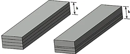
The problem considered in the study is to optimize the stacking sequences of laminated composite beam in order to obtain the minimum deflection parameter among all possible combinations of layer thicknesses for various boundary conditions. In Figure 2, the cross-section of composite beam with the same and various layer thicknesses satisfying the total thickness of ℎ are presented respectively.
Fig. 2. Cross-section of the beam for the same and various layer thicknesses.
𝑢𝑢(𝑥𝑥) = −𝐵𝐵𝐴𝐴111
11 𝑢𝑢1+ 𝐶𝐶7𝑥𝑥 + 𝐶𝐶8
𝑤𝑤(𝑥𝑥) =𝑝𝑝𝐷𝐷𝐷𝐷111
11[−𝐶𝐶1𝑒𝑒
−𝑝𝑝𝑝𝑝+ 𝐶𝐶
2𝑒𝑒𝑝𝑝𝑝𝑝−𝐴𝐴𝑝𝑝 55(
𝑞𝑞𝑥𝑥2
2 + 𝐶𝐶3𝑥𝑥)] + 1 𝐷𝐷11(
𝑞𝑞𝑥𝑥4
24 + 𝐶𝐶3
𝑥𝑥3
6 ) +𝐶𝐶4𝑥𝑥
2
2 + 𝐶𝐶5𝑥𝑥 + 𝐶𝐶6
where
𝑝𝑝 = √𝐷𝐷 −𝐴𝐴55𝐴𝐴11𝐷𝐷11
1112 𝐴𝐴11− 𝐷𝐷1111𝐴𝐴11𝐷𝐷11 (6)
By use of a computational programme, the integration coefficients can easily be obtained by applying the boundary conditions at both edges of the beam.
Optimization Method
Considering too many design parameters in an optimization problem will bring about too many solutions attendantly. Thus, instead of using the whole possible solutions and obtain the optimum, using an evolutionary technique in the optimization process would be inevitable. Genetic algorithm is widely used in the design of laminated composite structures that have many variables and different fitness functions. To solve the complex optimization problems by use of conventional optimization techniques can be difficult in many fields. Genetic algorithm (GA) is an evolutionary optimization technique using Darwin’s principal of survival of the fittest to improve a population of solutions [9]. The algorithm is generally based on natural selection, crossover and mutation which are also called as the genetic operators. Stacking sequences are the design variables that consist of fibre orientation angles (𝜃𝜃(𝑘𝑘)) where 𝑘𝑘 represents the number of layer. Therefore, the optimization problem may be written in a standard form such as:
Find: [𝜃𝜃(1)/𝜃𝜃(2)/𝜃𝜃(3)/𝜃𝜃(4)]
Minimize: 𝑤𝑤 (7)
Subject to: 0° ≤ 𝜃𝜃 ≤ 90°
The problem considered in the study is to optimize the stacking sequences of laminated composite beam in order to obtain the minimum deflection parameter among all possible combinations of layer thicknesses for various boundary conditions. In Figure 2, the cross-section of composite beam with the same and various layer thicknesses satisfying the total thickness of ℎ are presented respectively.
𝑢𝑢(𝑥𝑥) = −𝐵𝐵111𝐴𝐴11 𝑢𝑢1+ 𝐶𝐶7𝑥𝑥 + 𝐶𝐶8
𝑤𝑤(𝑥𝑥) = 𝑝𝑝𝐷𝐷𝐷𝐷111 11[−𝐶𝐶1𝑒𝑒
−𝑝𝑝𝑝𝑝+ 𝐶𝐶2𝑒𝑒𝑝𝑝𝑝𝑝− 𝑝𝑝 𝐴𝐴55(
𝑞𝑞𝑥𝑥2
2 + 𝐶𝐶3𝑥𝑥)] + 1 𝐷𝐷11(
𝑞𝑞𝑥𝑥4 24 + 𝐶𝐶3
𝑥𝑥3 6 ) +𝐶𝐶4𝑥𝑥22+ 𝐶𝐶5𝑥𝑥 + 𝐶𝐶6
where
𝑝𝑝 = √𝐷𝐷 −𝐴𝐴55𝐴𝐴11𝐷𝐷11 1112 𝐴𝐴11− 𝐷𝐷1111𝐴𝐴11𝐷𝐷11
(6)
By use of a computational programme, the integration coefficients can easily be obtained by applying the boundary conditions at both edges of the beam.
Optimization Method
Considering too many design parameters in an optimization problem will bring about too many solutions attendantly. Thus, instead of using the whole possible solutions and obtain the optimum, using an evolutionary technique in the optimization process would be inevitable. Genetic algorithm is widely used in the design of laminated composite structures that have many variables and different fitness functions. To solve the complex optimization problems by use of conventional optimization techniques can be difficult in many fields. Genetic algorithm (GA) is an evolutionary optimization technique using Darwin’s principal of survival of the fittest to improve a population of solutions [9]. The algorithm is generally based on natural selection, crossover and mutation which are also called as the genetic operators. Stacking sequences are the design variables that consist of fibre orientation angles (𝜃𝜃(𝑘𝑘)) where 𝑘𝑘 represents the number of layer. Therefore, the optimization problem may be written in a standard form such as:
Find: [𝜃𝜃(1)/𝜃𝜃(2)/𝜃𝜃(3)/𝜃𝜃(4)]
Minimize: 𝑤𝑤 (7)
Subject to: 0° ≤ 𝜃𝜃 ≤ 90°
The problem considered in the study is to optimize the stacking sequences of laminated composite beam in order to obtain the minimum deflection parameter among all possible combinations of layer thicknesses for various boundary conditions. In Figure 2, the cross-section of composite beam with the same and various layer thicknesses satisfying the total thickness of ℎ are presented respectively.
where:
𝑢𝑢(𝑥𝑥) = −𝐵𝐵111𝐴𝐴11 𝑢𝑢1+ 𝐶𝐶7𝑥𝑥 + 𝐶𝐶8
𝑤𝑤(𝑥𝑥) = 𝑝𝑝𝐷𝐷𝐷𝐷111 11[−𝐶𝐶1𝑒𝑒
−𝑝𝑝𝑝𝑝+ 𝐶𝐶2𝑒𝑒𝑝𝑝𝑝𝑝− 𝑝𝑝 𝐴𝐴55(
𝑞𝑞𝑥𝑥2
2 + 𝐶𝐶3𝑥𝑥)] +
1 𝐷𝐷11(
𝑞𝑞𝑥𝑥4
24 + 𝐶𝐶3
𝑥𝑥3 6 ) +𝐶𝐶4𝑥𝑥22+ 𝐶𝐶5𝑥𝑥 + 𝐶𝐶6
where
𝑝𝑝 = √𝐷𝐷 −𝐴𝐴55𝐴𝐴11𝐷𝐷11
1112 𝐴𝐴11− 𝐷𝐷1111𝐴𝐴11𝐷𝐷11 (6)
By use of a computational programme, the integration coefficients can easily be obtained by applying the boundary conditions at both edges of the beam.
Optimization Method
Considering too many design parameters in an optimization problem will bring about too many solutions attendantly. Thus, instead of using the whole possible solutions and obtain the optimum, using an evolutionary technique in the optimization process would be inevitable. Genetic algorithm is widely used in the design of laminated composite structures that have many variables and different fitness functions. To solve the complex optimization problems by use of conventional optimization techniques can be difficult in many fields. Genetic algorithm (GA) is an evolutionary optimization technique using Darwin’s principal of survival of the fittest to improve a population of solutions [9]. The algorithm is generally based on natural selection, crossover and mutation which are also called as the genetic operators. Stacking sequences are the design variables that consist of fibre orientation angles (𝜃𝜃(𝑘𝑘)) where 𝑘𝑘 represents the number of layer. Therefore, the optimization problem may be written in a standard form such as:
Find: [𝜃𝜃(1)/𝜃𝜃(2)/𝜃𝜃(3)/𝜃𝜃(4)]
Minimize: 𝑤𝑤 (7)
Subject to: 0° ≤ 𝜃𝜃 ≤ 90°
The problem considered in the study is to optimize the stacking sequences of laminated composite beam in order to obtain the minimum deflection parameter among all possible combinations of layer thicknesses for various boundary conditions. In Figure 2, the cross-section of composite beam with the same and various layer thicknesses satisfying the total thickness of ℎ are presented respectively.
By use of a computational programme, the integration coefficients can easily be obtained by applying the boundary conditions at both edges of the beam.
OPTIMIZATION METHOD
9 Advances in Science and Technology Research Journal Vol. 9 (26) 2015
many solutions attendantly. Thus, instead of using all the possible solutions and obtain the optimum, using an evolutionary technique in the optimiza-tion process would be inevitable. Genetic algo-rithm is widely used in the design of laminated composite structures that have many variables and different fitness functions. Solving complex optimization problems by the use of conventional optimization techniques can be difficult in many fields. Genetic algorithm (GA) is an evolutionary optimization technique using Darwin’s principal of survival of the fittestto improve a population of solutions [9]. The algorithm is generally ba-sed on natural selection, crossover and mutation which are also called genetic operators. Stacking sequences are the design variables that consist of fibre orientation angles (θ(k)) where k represents the number of layer. Therefore, the optimization problem may be written in a standard form such as: Find: [θ(1)/θ(2)/θ(3)/θ(4)]
Minimize: w
Subject to: 0° ≤ θ ≤ 90°
The problem considered in the study is to optimize the stacking sequences of laminated composite beam in order to obtain the minimum deflection parameter among all possible combi-nations of layer thicknesses for various boun-dary conditions. In Figure 2, the cross-section of composite beam with the same and various layer thicknesses satisfying the total thickness of are presented respectively.
The flowchart of genetic algorithm used in the study is illustrated in Figure 3. After an initial population of stacking sequences is generated, they are ranked from minimum to maximum with corresponding deflection parameters. New indi-viduals representing the stacking sequences are generated by crossover so as to swap one or two fiber orientation angle of two consecutive stack-ing sequences and the genetic diversity from one generation to another is maintained by mutation,
altering one random fiber orientation angle of a random stacking sequence in each generation.
RESULTS AND DISCUSSION
The composite beam is assumed to be con-structed of graphite/epoxy and under a uniform dis-tributed load where q(x) = 1000 N/m, a length of L
= 1 m and thickness of h = 0,02 m and the mechani-cal properties of graphite/epoxy are given as [10]:
E11= 241.5 GPa, E22= E33= 18.89 GPa
G23= 3.45 GPa, G12= G13= 5.18 GPa (8) υ23= 0.25, υ12= υ13= 0.24
In Table 1, the minimum deflection parameters and corresponding stacking sequences are pre-sented for various layer thicknesses and boundary conditions. The first term in layer thicknesses and stacking sequences indicates the first layer at the bottom of the beam where the last indicates the one at the top. There may be too many possible combi-nations of layer thicknesses for a composite beam depending on the variation and the number of lay-ers. For instance, in a four layered beam, although there is only one combination for a variation of
0.25 h, there are 84 possible combinations for a variation of 0.1 h. Since there are more possible combinations of layer thicknesses with a variation of 0.1 h, the minimum deflection parameters are obtained for this case in all boundary conditions.
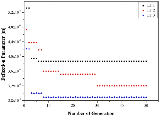
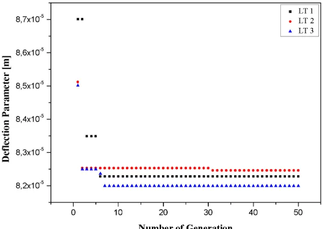
In Figure 4, Figure 5 and Figure 6, the varia-tion of deflecvaria-tion parameters with respect to the number of generation for C-C, C-F and S-S boundary conditions are presented respectively. The algorithm is carried out for a population of 100 individuals and a number of generation of 50 in (7)
Fig. 2. Cross-section of the beam for the same and various layer thicknesses
Table 1. The minimum deflection parameters and corresponding stacking sequences for various layer thicknesses and boundary conditions
Boundary condition Variation Layer thicknesses (× h) Deflection parameter [m] Stacking sequence
C-C
0.25 0.25/0.25/0.25/0.25 1.75226·10-5 0°/0°/0°/0°
0.2 0.2/0.2/0.2/0.4 1.75226·10-5 0°/0°/0°/0°
0.1 0.1/0.1/0.2/0.6 1.10796·10-6 0°/0°/0°/40°
C-F
0.25 0.25/0.25/0.25/0.25 3.87065·10-4 0°/10°/50°/40°
0.2 0.2/0.2/0.2/0.4 3.19941·10-4 20°/90°/70°/0°
0.1 0.4/0.1/0.4/0.1 2.89024·10-4 0°/10°/80°/0°
S-S
0.25 0.25/0.25/0.25/0.25 8.22771·10-5 0°/0°/10°/0°
0.2 0.2/0.2/0.2/0.4 8.24556·10-5 0°/0°/10°/0°
0.1 0.2/0.2/0.1/0.5 8.19918·10-5 0°/0°/10°/0°
Fig. 4. The variation of deflection parameters with respect to generation for C-C
11 Advances in Science and Technology Research Journal Vol. 9 (26) 2015
order not to stuck in a local minimum. The combi-nation of layer thicknesses (LT), satisfying the total thickness of the beam together, are considered for three cases. In LT1, the layer thicknesses are ob-tained for a variation of 0.25 which correspond to four layers with a same thickness of 0.25 h. In LT2
and LT3 the variation of 0.2 and 0.1 are consid-ered respectively. As it is obvious from the figures that the minimum values are obtained for a varia-tion of 0.1 (LT3) in all cases. For C-C boundary condition, the deflection parameters are very close to each other but the minimum value is obtained in 24th generation. For C-F, the minimum value is obtained in 8th generation and it is obtained in 7th generation for S-S boundary condition.
CONCLUSIONS
In this study, the stacking sequence of a com-posite beam is optimized by the use of an evolu-tionary technique in order to obtain the minimum deflection parameters for various boundary condi-tions. Unlike the studies with the same layer thick-nesses in the literature, the optimization process is carried out with different layer thicknesses. It is obvious from the results that, rather than the lay-ers with the same thicknesses, the minimum values are obtained for different layer thicknesses due to the further number of possible combinations. In further works, the optimization problem can be ex-panded by taking new design parameters into ac-count including strength, frequency and buckling.
REFERENCES
1. Walker M., Smith R.E.: A technique for the
multiob-jective optimisation of laminated composite structures
using genetic algorithms and finite element analysis.
Composite Structures, 62, 1, 2003, 123–128.
2. Conti P., Luparello S., Pasta A.: Layer thickness
op-timisation in a laminated composite. Composites Part B, 28B, 1997, 309–317.
3. Lee D.S., Morillo C., Bugeda G., Oller S., Onate E.: Mul-tilayered composite structure design optimisation using distributed/parallel multi-objective evolutionary algo-rithms. Composite Structures, 94, 3, 2012, 1087–1096.
4. Brighenti R.: Fibre distribution optimisation in
fibre-reinforced composites by a genetic algorithm.
Com-posite Structures, 71, 2005, 1–15.
5. Khosravi P., Sedaghati R.: Design of laminated
com-posite structures for optimum fiber direction and layer thickness, using optimality criteria. Structural and Multidisciplinary Optimization, 36, 2, 2008, 159–167.
6. Soldatos K.P., Tımarcı T.: A unified formulation of
laminated composite, shear deformable five-degrees-of-freedom cylindrical shell theories. Composite Structures, 25, 1993, 165–171.
7. Timarci T., Soldatos K.P.: Comparative dynamic stu-dies for symmetric cross-ply circular cylindrical shells on the basis of a unified shear deformable shell theory. Journal of Sound Vibration, 187, 4, 1995, 609–624.
8. Karaçam F.: MSc. Thesis (In Turkish), Trakya
Univer-sity, Institute of Science, Turkey, Edirne, 2005. 9. Goldberg D.E.: Genetic Algorithms in Search,
Optimi-zation and Machine Learning. Addison-Wesley Long-man Publishing Co., Inc., USA, Boston, MA, 1989.
10. Karama K.S., Afaq S., Mistou S.: Mechanical
beha-viour of laminated composite beam by the new mul-ti-layered laminated composite structures model with
transverse shear stress continuity. International
Jour-nal of Solids and Structures, 40, 2003, 1525–1546.