http: // www.ijrtsm.com© International Journal of Recent Technology Science & Management 23
ISSN : 2455-9679
[Gupta et al. , 3(10), Oct 2018] Impact Factor : 2.865
IJRTSM
INTERNATIONAL JOURNAL OF RECENT TECHNOLOGY SCIENCE & MANAGEMENT
“
DESIGN, ANALYSIS USING CAE TOOLS FOR A 3-AXIS VERTICAL MILLING MACHINE ”
Divyam Gupta
1,
Purushottam Kumar Sahu
21PG, Scholar, Dept. of Mechanical Engineering, BMCT Indore, M.P., India. 2 HOD, Dept. of Mechanical Engineering, BMCT Indore, M.P., India.
ABSTRACT
CNC technology has proved to be of great importance for manufacturing sector. The use of contemporary CNC systems along with higher computational and memory storage capacity of modern computer systems has redefined the shop floor automations strategies for modern manufacturing sectors. One of the biggest challenges today is how to make the CNC technology affordable, simpler and available to an extent that even a hobbyist/ occasional user can think of owing such technology. The focus of the this paper is to judge the design of a new CNC (milling machine) tool structure designed for sculptured surface machining using tool Finite Element Method (FEM) analysis in ANSYS.
Keyword: Sculptured surface machining, Finite Element Method (FEM).
I.
I
NTRODUCTIONThe machine tool structure constitutes an important part of total cost of a CNC machine system. Thus a simpler cost effective machine tool design can directly reduce the overall cost of a CNC system. The problem is not only about the reduction in the machine tool fabrication, but other costs associated with usage, repair and up-gradation or enhancements etc. should also be lesser. Thinking this as an overall objective a simplified machine tool unit for sculptured surface machining has been designed. The cutting forces has been calculated after constraining the range of cutting specification and types of cutting tools to be used. A systematic study has been done for the selection of the drive motors and router as spindle drive. The objective of maximizing the tool traverse in all 3 directions so as to enable to cutting tool to approach the maximum machining volume for material removal subject to the constraint of sizes of standard available machine components used in CNC machines has also been studied.
II.
L
ITERATURER
EVIEWhttp: // www.ijrtsm.com© International Journal of Recent Technology Science & Management 24
ISSN : 2455-9679
[Gupta et al. , 3(10), Oct 2018] Impact Factor : 2.865
Lee et al [2] observed that of the primary reasons for low productivity is large mass of the moving parts of machine tools, which cannot afford high acceleration and deceleration, encountered during operation. Moreover, the vibrations of the machine tool structure are among the other causes that restrict high speed operations. The slides of high speed CNC milling machines were designed with fiber reinforced composite materials to overcome this limitation. The vertical and horizontal slides of a large CNC machine were manufactured by joining high-modulus carbon-fiber epoxy composite sandwiches to welded steel structures using adhesives and bolts. These composite structures reduced the weight of the vertical and horizontal slides and increased damping by 1.5 to 5.7 times without sacrificing the stiffness.
Xiangsheng et al [3] analyzed the influence of configuration parameters on dynamic characteristics on machine tools in working space, the configuration parameters have been suggested based on the orthogonal experiment method. Dynamic analysis of newly designed milling machine for producing turbine blades has been conducted by utilizing the model synthesis method. The finite element model is verified and updated by experimental modal analysis (EMA) of machine tool. The result obtained by modal synthesis method is compared with model finite element method (FEM) result as well. According to the orthogonal experiment method, four configuration parameters are considered as four factors for dynamic characteristics. The influence of configuration parameters on the first three natural.
Hung et al [4] emphasised that prediction of machining stability is of great importance for the design of a machine tool capable of high-precision and high-speed machining. The machining performance is determined by the frequency characteristics of the machine tool structure and the dynamics of the cutting process expressed in terms of a stability lobe diagram. The aim of this study is to develop a finite element model to evaluate the dynamic characteristics and machining stability of a vertical milling system. Rolling interfaces with a contact stiffness defined by Hertz theory were used to couple the linear components and the machine structures in the finite element model. Using the model, the vibration mode that had a dominant influence on the dynamic stiffness and the machining stability was determined. The results of the finite element simulations reveal that linear guides with different preloads greatly affect the dynamic behavior and milling stability of the vertical column spindle head system. These results were validated by performing vibration and machining tests. It can be concluded that the proposed model can accurately evaluate the dynamic performance of machine tool systems designed with various configurations and with different linear rolling components.
Abele et al [5] presented the state of the art in machine tool main spindle units with focus on motorized spindle units for high speed and high performance cutting. Detailed information is provided about main components of spindle units regarding the historical development, recent challenges and future trends. Advanced methods of modelling the thermal and dynamical behavior of spindle units are shown in overview with specific results. Furthermore concepts of sensor and actuator integration were presented which all focused on increasing productivity and reliability.
Fenghe et al [6] observed that ram is a very important component of super heavy duty computer numerical control (CNC) floor type boring-milling machine and deformation of ram is a significant source causing errors in machining process. To compensate the deformation error of super-heavy-duty CNC floor type boring-milling machine, based on force analysis theory, the law and compensation measures of deformation of ram are investigated. Based on the principle of torque (force) balance of the ram components, the formulas of compensation forces and compensation torques were obtained. According to theoretical analysis results and the structural characteristics, rods compensation, hydrostatic pressure compensation and wire rope compensation measures have been conducted to compensate the deformation error of ram. The experiments and computer simulation results show that the straightness of the ram at its overhanging end meets the national machinery industry standards.
http: // www.ijrtsm.com© International Journal of Recent Technology Science & Management 25
ISSN : 2455-9679
[Gupta et al. , 3(10), Oct 2018] Impact Factor : 2.865
tool stick out which is modeled by Timoshenko beam elements. The proposed methods allow prediction of frequency- response functions at the tool tip by receptance coupling of tools and holders to the spindle, as well as analyzing the influence of relative wear at the contact by removing discrete contact springs between the holder and spindle. The techniques are experimentally illustrated and their practical use in high speed milling applications were elaborated.
Aknouche et al [8] described some interesting results about the tool wear. In a machining process of the North African Aleppo pine the correlation between the tool wear and cutting forces shows that, the running period is about 850m of cutting length. In this period, angle variation is unstable before it is around−1.1◦ in the stability zone. This confirms the existence of the first two separate areas that characterize the behavior of the tool edge recession, which are running (abrupt wear) and the linear wear (known as stability period). As a consequence it can be said that an angle is a good criterion for tool wear estimation in these practical machining conditions. It is proposed to use the same approach with other tools. Another important aspect, particularly in the case of wood is to estimate the surface quality by measuring its roughness and wettability and to make the link with tool wear that is the transformation of wood by removal of matter generates new surfaces which have a precise functionality and will all receive protective films or glues. This highlights the need to characterize wood surface wettability. Depending on the various fields of application, a future aim of this study is to make practical recommendations to wood professionals, summarized in a good practice guide to enhance Aleppo pine solid woods value.
Cao et al [9] observed that chatter stability of machine tool is dependent on the dynamic behavior of spindle systems. The alternative method was presented to predict the chatter stability lobes of high-speed milling with consideration of speed-varying spindle dynamics. Based on the dynamic model of the high-speed spindle, systematically investigations were carried out on the speed effects. It was found that the gyroscopic moment of the spindle shaft can increase the cross FRFs, but can hardly affect the direct FRFs (frequency response function) at the tool tip due to the damping of the spindle system. The centrifugal forces on both the shaft and bearings lower the overall spindle system stiffness evidently as the speed increases. It is shown that the stability lobes with consideration of speed effects shift to the low speed range significantly. The proposed method can provide a guideline to estimate the cutting performance of high-speed spindles during the design stage.
Jonsson et al [10] highlighted that while designing CNC machine tools it is important to consider the dynamics of the control, the electrical components and the mechanical structure of the machine simultaneously. This paper describes the structure and implementation of a concept for real-time simulation of such machine tools using a water jet cutting machine as an application. The concept includes a real control system, simulation models of the dynamics of the machine and a virtual reality model for visualization. However, already from the initial simulation results presented in the paper it could be concluded that the influence of structural flexibility on manufacturing accuracy is of importance at desired feeding rates and accelerations. The fully automated implementation developed in this work is a promising base for dealing with this trade-off between productivity and accuracy of the manufacturing process through multidisciplinary optimization.
Zulaika et al [11] has presented an integrated approach for designing large milling machines, taking both mass reduction of mobile structural components and the maximum material removal rate into account. This approach considers milling operation and a productivity target as a starting point, and then deals with the design of the machine to achieve the targeted productivity with structural components of minimum mass. The procedure is based on modelling the interactions between process and machine by means of a stability model of the milling process in modal coordinates. The model allows the identification of the mechanical design parameters that limit the productivity as well as the threshold values that must be met to ensure the targeted productivity. Those values are reached in an iterative procedure that minimizes the mass of the critical structural components of the machine.
http: // www.ijrtsm.com© International Journal of Recent Technology Science & Management 26
ISSN : 2455-9679
[Gupta et al. , 3(10), Oct 2018] Impact Factor : 2.865
controlling the position and orientation of the machine tool during the machining operation. Dynamic simulations and experimental results using a closed-loop control with position feedback were presented to illustrate the performance and features of the system. Unlike conventional full-scale manufacturing machines, the developed machine provided a number of advantages, including fast dynamic response, have simpler design, low cost, and a compact but relatively large workspace without motion singularities.
III.
M
ODELLING OFM
ACHINET
OOLS
TRUCTUREP
ROTOTYPEProposed work was to analyze the design of a machine tool structure using CAE tools with an overall idea that what a machine would look like. With help of software Creo parametric 2.0 structural design and axis drives of the machine were optimized for work volume of the machine.
Fig.1 Machine tool base design in first Iteration
Iteration 1.0
First iteration was to develop a basic design of structure starting from the foundation with its components in x-axis direction. It was decided to manufacture machine designed from simple material available in the market, making it convenient at user end to manufacture its own spares using conventional machine tool and thus eliminating any idea to get spares from any store. Then mild steel plates were selected as low cost raw material. Guide rails were fitted, length of x-axis was constrained, vertical columns were placed during the modelling stage it was observed that it required use of too many fasteners to connect the different structural members involved in the structure. It may adversely affect the accuracy and may also result in a noisy working of the proposed machine. The modular structure was too much exposed which will be prone to outside dust which in turn can reduce the service life of the moving parts and the components associated with them in the machine. Also proper utilization of the bounding box which envelops the whole machine wasn’t there. As shown in the figure there was no use of area below the stand which in figure 1 is shaded green. A structure has more chances of its vibrations when its legs are not locked with each other from the base.
Iteration 2.0
http: // www.ijrtsm.com© International Journal of Recent Technology Science & Management 27
ISSN : 2455-9679
[Gupta et al. , 3(10), Oct 2018] Impact Factor : 2.865
the top of the columns the guide rails for X-Axis movement restrict the area movement of Z-Axis and its placementwas major problem in this model.
Figure 2: Machine tool base design in second Iteration
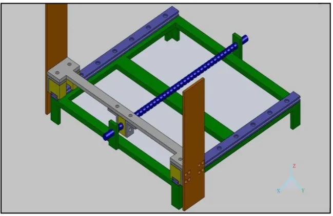
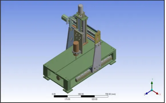
Iteration 3.0
There were many problems when starting with x-axis as base. Criteria set for work started from y axis. When the dimensions of y-axis was constrained and adjusted according to the movement for z-axis. It was observed that modelling should be done starting from making a yz assembly. It was decided to use parametric software rather than non-parametric solid works as many things were interconnected like if any chances done on the machine structure also change in its assembly. Software called Pro-engineer was used for designing. After number of iterations within the system component by component, a structure shown in figure 3 was developed, many small parts installed on the machine for the visual realism. Subsequent modifications were required during the CAE analysis and evaluation phase of the proposed structure. The model built in Pro-e was converted into IGES format for analysis using CAE tools.
Figure 3: Iteration 3.0
IV.
S
ELECTION OFS
TANDARDC
OMPONANThttp: // www.ijrtsm.com© International Journal of Recent Technology Science & Management 28
ISSN : 2455-9679
[Gupta et al. , 3(10), Oct 2018] Impact Factor : 2.865
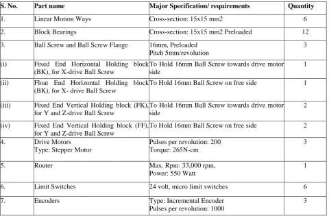
Table 1: Standard component purchased for present project.
S. No. Part name Major Specification/ requirements Quantity
1. Linear Motion Ways Cross-section: 15x15 mm2 6
2. Block Bearings Cross-section: 15x15 mm2 Preloaded 12
3. Ball Screw and Ball Screw Flange 16mm, Preloaded
Pitch 5mm/revolution
3
(i) Fixed End Horizontal Holding block
(BK), for X-drive Ball Screw
To Hold 16mm Ball Screw towards drive motor side
1
(ii) Float End Horizontal Holding block
(BK), for X- drive Ball Screw
To Hold 16mm Ball Screw on free side 1
(iii) Fixed End Vertical Holding block (FK), for Y and Z-drive Ball Screw
To Hold 16mm Ball Screw towards drive motor side
2
(iv) Fixed End Vertical Holding block (FF), for Y and Z-drive Ball Screw
To Hold 16mm Ball Screw on free side 2
4. Drive Motors
Type: Stepper Motor
Pulses per revolution: 200 Torque: 265N-cm
3
5. Router Max. Rpm: 33,000 rpm,
Power: 550 Watt
1
6. Limit Switches 24 volt, micro limit switches 6
7. Encoders Type: Incremental Encoder
Pulses per revolution: 1000
3
V.
C
ALCULATIONCALCULATION OF LOAD ON ONE BLOCK OF X-AXIS:
Fig 4: Load layouts of x-axis
Weight of the plate over the four blocks (W) = 100 N
http: // www.ijrtsm.com© International Journal of Recent Technology Science & Management 29
ISSN : 2455-9679
[Gupta et al. , 3(10), Oct 2018] Impact Factor : 2.865
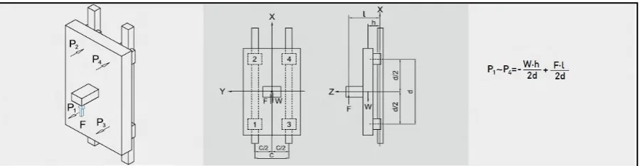
CALCULATION OF LOAD ON ONE BLOCK OF Y-AXIS:
Fig 5: Load layout of y-axis
Weight of the plate over the four blocks (W) = 15 N Force is the weight hanging (F) = 215 N l, h, c, d are the distances as shown above
l= 33mm, h = 30mm, c = 104mm, d = 70mm.
P1 = P2 = P3 = P4 = -31.947 N (negative is for the direction) Pt1 = Pt3= 57.5 N
Pt2 = Pt4 =57.5 N
CALCULATION OF LOAD ON ONE BLOCK OF Z-AXIS:
Fig 6: Load layout of z-axis
Weight of the plate over the four blocks (W) = 15 N Force is the weight hanging (F) = 50 N l, h, c, d are the distances as shown above
l= 33mm, h = 30mm, c = 104mm, d = 70mm. P1 = P2 = P3 = P4 = 8.5714 N
VI.FEMANALYSISOFMAINMACHINESTRUCTURECONSIDERINGALLCOMPONENTS
Using the FEM Methodology the two main systems of the machine prototype have been analysed in “ANSYS 10.0” for the type of loadings they will be subjected. The section below presents the results for the FEM analysis of these two systems of the machine prototype.
Geometry Generation
http: // www.ijrtsm.com© International Journal of Recent Technology Science & Management 30
ISSN : 2455-9679
[Gupta et al. , 3(10), Oct 2018] Impact Factor : 2.865
between two components. In case of the present model of machine structure the contacts were given manually. ANSYS support many types of contacts/ connections and some of them used in designing the machine structure were bonded, frictional, translational, and revolute.The machine tool structure has to be tested for static load conditions. Hence, the static structural module was considered which would be best for this kind of analysis.
Materials properties used for type of material used for each component in machine structure were added. Two properties essential for analysis in ANSYS are Young’s Modulus and Poisson's Ratio. 2 different materials were used in the present model. The essential properties of these materials have been listed in table 2.
Table 2: Properties for Mild Steel and Hardened Steel
S. No. Description/ Material Property Value/ Magnitude (M.S.) Value/ Magnitude (H.S.)
1 Density 7.85x10⁻⁶ kg/mm3 7.85x10⁻⁶ kg/mm3
2 Young's Modulus 2x10⁵ MPa 2.08ex105 MPa
3 Poisson's Ratio 0.3 0.33
4 Compressive Yield Strength 250 MPa 250 MPa
5 Tensile Yield Strength 250 MPa 250 MPa
6 Tensile Ultimate Strength 460 MPa 460 MPa
7 Reference Temperature 22°C 22°C
8 Bulk Modulus 1.6667x10⁵ MPa 2.0392x10⁵ MPa
9 Shear Modulus 76923 MPa 78195 MPa
http: // www.ijrtsm.com© International Journal of Recent Technology Science & Management 31
ISSN : 2455-9679
[Gupta et al. , 3(10), Oct 2018] Impact Factor : 2.865
Fig 8: Details of the Equivalent Stress
Fig 9: Deformation of whole structure
http: // www.ijrtsm.com© International Journal of Recent Technology Science & Management 32
ISSN : 2455-9679
[Gupta et al. , 3(10), Oct 2018] Impact Factor : 2.865
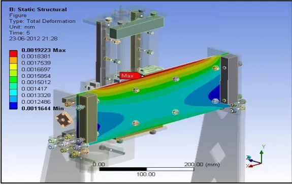
Fig 11: Deformation on the back plate of y-axis
VII.
R
ESULTS FOR STATIC STRUCTURAL ANALYSIS OF MACHINE PROTOTYPEa) Equivalent stress (Von-Mises)
As apparent from the figure 8, the maximum equivalent (Von-Mises) stress under the load of standard gravity is 3.5748 MPa. The part at which maximum equivalent stress is BS connector and its material is mild steel, the yield tensile strength of mild steel is 250Mpa. So, the structure under gravitational load is quite safe. This region is at the location where the BS connector is fastened with machine screws to the ball-screw flange of Y-axis drive unit.
(b) Maximum Deformation
The maximum deformation for the whole structure with standard gravity has been shown in figure 9. The magnitude of the maximum deformation is 0.03 mm which is on the tip of the cutting tool. This deformation is due to overhang which is justified for any cutting tool, otherwise from the coloured chart it is clear that till y-z connector plate of z-axis the deformation is of range 0.004, which is negligible. The overhang can be avoided as it is clear that deformation starts getting worse from the aluminium back-plate on which router mounting bracket have been attached. To avoid this deformation, aluminium back plate can be modified by adding two T-section stiffeners in front side vertically on it. This will reduce the deformation of this plate considerably. Another remedy could be to select a hard aluminium alloy material for this plate like aluminium 6061. Deformations on other major parts are shown in the figure 10 and 11. This structure is quite safe as the values of the deformations are around 0.1micron. The maximum stress levels are also less than 4.0MPa.
VIII.
C
ONCLUSIONIn the present work a detailed study for the design development and evaluation has been done. It is apparent from the results that the design of the machine structure is safe and suitable.
REFERENCES
[1] Ching Yuan Lin, Jui Pin Hung and Tzuo Liang Lo, “Effect of preload of linear guides on dynamic characteristics of a vertical column–spindle system”, International Journal of Machine Tools & Manufacture, vol. 50, pp. 741-746, 2011.
http: // www.ijrtsm.com© International Journal of Recent Technology Science & Management 33
ISSN : 2455-9679
[Gupta et al. , 3(10), Oct 2018] Impact Factor : 2.865
[3] GAO Xiangsheng, ZHANG Yidu, ZHANG Hongwei and WU Qiong, “Effects of Machine Tool Configuration on Its Dynamics Based on Orthogonal Experiment Method”, Chinese Journal of Aeronautics, vol. 25, pp. 285-291, 2012.
[4] Jui Pin Hung, Yuan Lung Lai, Ching Yuan Lin and Tzu Liang Lo, “Modeling the machining stability of a vertical milling machine under the influence of the preloaded linear guide”, International Journal of Machine Tools & Manufacture, vol. 51, pp. 731- 739, 2011.
[5] E. Abele, Y. Altintas and C. Brecher, “Machine tool spindle units”, CIRP Annals - Manufacturing Technology, vol. 59, pp. 781-802, 2010.
[6] WU Fenghe, QIAO Lijun and XU Yaoling, “Deformation Compensation of Ram Components of Super-heavy-duty CNC Floor Type Boring and Milling Machine”, Chinese Journal of Aeronautics, vol. 25, pp. 269-275, 2012.
[7] Mehdi Namazi, Yusuf Altintas, Taro Abe and Nimal Rajapakse, “Modeling and identification of tool holder–spindle
interface dynamics”, International Journal of Machine Tools & Manufacture, vol. 47, pp. 1333-1341, 2007.
[8] H. Aknouche, A. Outahyon, C. Nouveau, R. Marchal, A. Zerizer and J.C. Butaud, “Tool wear effect on cutting forces: In routing process of Aleppo pine wood”, Journal of Materials Processing Technology, vol. 2 0 9, pp. 2918– 2922, 2009.
[9] Hongrui Cao, Bing Li and Zhengjia He, “Chatter stability of milling with speed- varying dynamics of spindles”, International Journal of Machine Tools & Manufacture, vol. 52, pp. 50–58, 2012.
[10] Anders Jo¨nsson, Johan Wall and Go¨ran Broman, “A virtual machine concept for real- time simulation of machine tool dynamics”, International Journal of Machine Tools & Manufacture, vol. 45, pp. 795–801, 2005.