Sharif University of Technology
Scientia IranicaTransactions B: Mechanical Engineering www.scientiairanica.com
Thermally induced vibration of an electro-statically
deected functionally graded micro-beam considering
thermo-elastic coupling eect
I. Jafarsadeghi-pournaki, G. Rezazadeh
, M.R. Zamanzadeh and R. Shabani
Department of Mechanical Engineering, Urmia University, Urmia, Iran.Received 19 December 2012; received in revised form 26 September 2013; accepted 16 December 2013
KEYWORDS Thermally induced vibration;
FGM;
Thermo-elastic coupling;
Electrostatic load.
Abstract. This study investigates the dynamic response of an electrostatically deected capacitive cantilever Functionally Graded (FG) micro-beam subjected to a harmonically varying thermal load, which incites vibration due to the dierent material properties of the beam constituents and the thermo-elastic coupling eect. The FG beam is made of a mixture of metal and ceramic, where the material properties vary continuously through the thickness according to an exponential distribution law (E-FGM). Assuming the Euler-Bernoulli beam theory and the innite speed of heat transportation, the equation of motion and the conventional coupled energy equation are derived. Applying Galerkin formulation and then using the Rung-kutta method as an ecient numerical tool, these equations are simultaneously solved. Changing the ceramic constituent percentage of the bottom surface, ve dierent types of FGM micro-beams are investigated and the results are presented for all types. Numerical results show the response of a cantilever FG micro-beam subjected to a harmonically varying temperature input. Moreover, the inuences of the beam ceramic constituent percentage on stability, vibrational behavior and natural frequency are presented.
© 2014 Sharif University of Technology. All rights reserved.
1. Introduction
A new generation of advanced composites includes Functionally Graded Materials (FGMs). These materi-als have a smooth variation of material properties along one or more directions. Better stress relaxation and the potential to resist large temperature gradients are the main advantages of this class of materials. Typi-cally, FGMs consisting of thermal-resisting ceramic and fracture-resisting metal are composites whose volume
*. Corresponding author. Tel.: +98 9141451407; Fax: +98 441 3368033
E-mail addresses: [email protected] (I. Jafarsadeghi-pournaki); [email protected] (G. Rezazadeh); [email protected] (M.R. Zamanzadeh); [email protected] (R. Shabani)
fractions of constituents vary gradually, resulting in a continuous change in physical properties [1-3].
The study of the dynamic behavior of FG struc-tures under mechanical or thermal loads certainly has been an active subject of research, as evidenced by the many analytical and numerical analyses published in literature. Numerous researchers have studied the vibration and heat transfer process of these kinds of beam. Sankar and his co-workers [4,5] carried out the elasticity solutions of thermally loaded FG beams. By considering shear deformation, Chakraborty et al. [6] presented a new beam element to study the thermo-elastic behavior of FG beam structures. Using the Meshless Local Petrov-Galerkin method (MLPG), Qian and Ching [7] obtained the numerical solutions for static deformation, and free and force vibrations of a FG cantilever beam, while Ching and Yen [8]
analyzed the 2D FG solids, which are subjected to either mechanical or thermal loads. By means of dierent higher order shear deformation theories and the Classical Beam Theory (CBT), the free vibration of a FG beam is presented by Aydogdu and Taskin [9]. Their results showed that CBT gives higher results and, also, they claimed that vibration frequencies, mode shapes and dynamic response are considerably changed by thickness variation, temperature change, slenderness ratio, volume fraction index, FG layer thickness, and end support conditions. Based on the Timoshenko beam theory, Xiang and Yang [10] explored both free and forced vibration of an FG beam with changeable thickness under thermally induced initial stresses. Kapuria et al. [11] proposed a nite element model for static and free vibration responses of layered FG beams using a third-order theory and its experimental validation. Li [12] presented a new unied approach to investigate the static and free vibration behavior of Euler-Bernoulli and Timoshenko beams. Using the modied dierential quadrature method, Pradhan and Murmu [13] studied the thermo-mechanical vibration analysis of FGM beams and sandwich beams resting on a variable Winkler foun-dation. Abbasi et al. [14] used a Galerkin based nite element method to analyze the vibration behavior of a FG Timoshenko beam under lateral thermal shock with coupled thermo-elastic assumption, and, similarly, Babaei et al. [15] studied the thermo-elastic vibration of FG beams under lateral thermal shock with the Euler-Bernoulli beam assumptions. Sina et al. [16] developed a new beam theory, dierent from the traditional rst-order shear deformation beam theory, with the purpose of analyzing the free vibration of FG beams considering dierent boundary conditions and making comparisons between various beam theories. Mahi et al. [17] presented an exact solution to study the free vibration and frequency response of a beam made of symmetric FG materials. In their work, the beam is assumed to be initially stressed by a temperature rise through the thickness. Free and force vibration analysis of FG beams considering the temperature dependency of material properties is discussed by Azadi [18]. In his work, the material properties were assumed to be temperature-dependent. The two-dimensional solution for a simply supported beam made of FG material subjected to arbitrary time-dependent lateral thermal shock loads, using the semi-analytical nite element method, was undertaken by Afshar et al. [19]. The equation of motion and the conventional coupled en-ergy equation are simultaneously solved to obtain the displacement components and temperature distribu-tion in the beam. Malekzadeh and Shojaee [20] carried out the dynamic response of FG beams under a moving heat source considering the material properties to be temperature-dependent. A two-dimensional Finite
Element Method (FEM) is employed to obtain the temperature distribution throughout the beam. Then, the eect of a two-dimensional variation of temperature on the dynamic response of an FG beam with arbitrary boundary conditions is formulated, based on the rst-order shear deformation beam theory (FSDBT). The dynamic stiness method is developed to investigate the free vibration behavior of FG beams by Su et al. [21]. Hemmatnezhad et al. [22] analyzed the large-amplitude free vibration of FG beams through a nite element formulation. They studied the inuences of the power-law exponent, vibration amplitude, beam geometrical parameters and end supports on the free vibration frequencies.
Recently, the emerging technology of micro- and nano-electromechanical systems (MEMS and NEMS) has seen dramatic progress in fabricating and testing new devices, creating innovative applications, and proposing novel technologies. Their light weight, small size, low-energy consumption and durability make them even more attractive. Accurate analysis of various eects on the characteristics of resonators, such as resonant frequencies and quality factors, is cru-cial for designing high-performance components [23]. Many authors have studied the vibration and heat transfer process of micro- and nano-beams. Laser-induced vibration of micro-beams is investigated by Sun et al. [24,25] considering a two dimensional hy-perbolic heat conduction model with one relaxation time. Applying dierent boundary conditions, they de-veloped the coupled thermo-elastic vibration of a micro scale beam resonator induced by pulsed laser heating. Mohammadi-Alasti et al. [26] studied the static be-havior of FG cantilever micro-beams and their static instability, when the beam is subjected to a nonlinear electrostatic pressure and temperature changes. They derived nonlinear integro-dierential thermo-electro-mechanical equations based on the Euler-Bernoulli beam theory. Most recently, the static and dynamic behavior of the FG micro-beam, based on Modied Couple Stress Theory (MCST), subjected to nonlinear electrostatic pressure and thermal changes, regarding convection and radiation, is investigated by Zaman-zadeh et al. [27]. Youssef and Elsibai [28] discussed the vibration of a gold nano-beam induced by dierent types of thermal loading. Also, in another work, Youssef [29] carried out the solution of vibration of a gold nano-beam resonator induced by thermal shock in the context of generalized thermoelasticity with variable thermal conductivity.
Many attempts have been made to study the vibration and heat transfer process of beams. The above-mentioned articles reveal that there has been widespread study of the vibrational behaviour of both homogenous and FG beams under either mechanical or thermal loads. More recently, there has been
investigation into thermally induced vibration of (only) pure metal micro- and nano-beams. To the best of the authors' knowledge, no previous work has been done concerning the coupled thermoelastic vibrational behavior of a micro beam made of FG materials, which is subjected to not only electrostatic pressure, but also harmonically varying thermal load. It must be pointed out that the problem of sinusoidal heat source can arise when a dynamic remote capacitive temperature sensor is used to measure rotating hot objects such as turbine blades. In this study, using the Galerkin based dis-cretizing method, the coupled thermo-elastic vibration of a capacitive FG Euler-Bernoulli micro-beam induced by harmonic thermal loads is investigated. Moreover, the eect of ceramic constituent percentage on vibra-tion and natural frequency is determined and results are considered to highlight the behavioral dierence of FG material micro beams with pure metal ones.
2. Model description and mathematical modeling
2.1. Material properties
The schematic diagram of the FG micro-beam is presented in Figure 1. The neutral axis and coordinates of the composite beam are shown in this gure, too. The studied model is a cantilever capacitive FG micro-beam with a rectangular cross section, with dimensions of length L(0 x L), width b( b=2 y b=2) and thickness h( h=2 z h=2). The h=L ratio is assumed to be small enough to eliminate the shear deformation eects. We dene the x axis along the axis of the beam, and the y and z axes correspond to the width and thickness, respectively. In equilibrium, the beam is unstrained and unstressed.
In this study, the material properties of the FG beam are assumed to vary through the thickness according to an exponential low function. Assuming z = z + h=2, the exponential law is given by [27]:
P (z) = Pte0z= Pte0(z+h=2); 0= 1hln
Pb
Pt
:
(1) P (z) denotes a typical material property. Pt and
Pb denote the values of the properties at the top
and bottom of the FG beam. It is assumed that the top surface is made of pure metal (Pt = metal
properties), but the bottom surface from a mixture of metal and ceramic. Also, it is assumed that the ceramic constituent percentage of the bottom surface varies from 0% to 100%. In order to determine the material properties of the bottom surface (Pb), a volume fraction
of material is used [27]:
Pb= VcPc+ VmPm; (2)
where V is the volume fraction, and subscripts, \m" and \c", stand for metal and ceramic, respectively. So, Vm and Vc are the volume-fractions of the metal and
ceramic, respectively, and are related by:
Vm+ Vc= 1: (3)
Changing the ceramic constituent percentage of the bottom surface, ve dierent types of FG micro-beam are investigated. Using the above mentioned equations, parameter 0 is specied for some material properties,
as follows: = h1ln
Eb
Em
; =h1ln
b
m
;
= h1ln
Kb
Km
; = 1hln
b
m
;
= 1hln
Cb
Cm
; S = 1hln
b
m
; (4) in which E, , K, , C and denote the Young's
modulus of elasticity, thermal expansion coecient, thermal conductivity, density, specic heat and Pois-son's ratio, respectively.
2.2. Dynamic equation of motion
According to the basic hypotheses of Euler-Bernoulli beams and the one-dimensional beam theory, the dis-placement eld for a FG beam can be written as [30]:
u = u0 z@W@x ; = 0; W = W (x; t); (5)
where u0 is the axial displacement of the beam in the
reference plane and u, and W are the x, y and z
components of the displacement vector, respectively. The axial strain of the beam, based on the Euler-Bernoulli beam theory, is expressed as [30]:
"x= dudx = @u@x0 z@ 2W
@x2 : (6)
The resultant stress, considering temperature changes for the Euler-Bernoulli beam, in a cross section area of the micro-beam, using Hooke's law, can be presented as [30]:
x= E(z) ("x (z)(x; z; t))
= E(z)
@u0(x; t)
@x z
@2W (x; t)
@x2
E(z)(z)(x; z; t); (7) where = T (x; z; t) T1is the temperature increment
of the beam, measured with respect to a reference (environment) temperature (T1). It is worth pointing
out that for plain stress conditions, E and are equal to E and , respectively, and for plain strain condition, are E=(1 2) and 1 + , respectively [31]. Under no
axial force, the equilibrium equations of the cantilever FG micro-beam are considered as:
Z
AxdA =
Z
AE(z)
@u0(x; t)
@x z
@2W (x; t)
@x2
(z)(x; z; t)
dA = 0; (8) Z
AxzdA =
Z
AzE(z)
@u0(x; t)
@x z
@2W (x; t)
@x2
(z)(x; z; t)
dA = M: (9)
As a result, from Eq. (8), @u0(x;t)
@x can be determined
as:
@u0(x; t)
@x = 1
~ A
~
B@@x2W2 + FT
: (10)
The parameters appeared in Eq. (10) are:
~ A =
Z h=2
h=2e
(z+h=2)dz; (11)
~ B =
Z h=2
h=2ze
(z+h=2)dz;
FT =
Z h=2
h=2me
(z+h=2)(+)(x; z; t)dz:
Substituting @u0(x;t)
@x into the moment equilibrium
equation (Eq. (9)), the motion equation of a FG beam subjected to an external heat source may be obtained as:
(EI)eq@ 2W
@x2 = M MT; (12)
in which M is the external bending moment in a given section produced from the electrostatic force acting along the micro-beam and W is the transverse deection. (EI)eq and MT are the equivalent bending
stiness and thermal moment, respectively:
(EI)eq=
Z
A
zE(z)
R
AzE(z)dA
R
AE(z)dA
z2E(z)dA; (13)
MT(x; t) =
Z
A
z R
AE(z)dA
E(z)FT
zE(z)(z)(x; z; t)
dA: (14)
The governing motion equation of the transversal displacement of a FG micro-beam, W (x; t), actuated by an electrical load and thermal moment, is written as [31-25]:
(EI)eq@
4W (x; t)
@x4 +
@2M
T(x; z; t)
@x2
+ (A)eq@
2W (x; t)
@t2 + c
@W (x; t)
@t = F (W; V ):(15)
The micro-beam may be assumed subjected to a viscous damping, which can be due to squeeze-lm damping. This eect is approximated by an equivalent external damping coecient per unit length (c) [23]. Since the micro beam is assumed to be subjected to a bias DC voltage, an electrostatic distributed force is introduced as [31]:
F (W; V ) = 2(g"0bV2
0 W )2; (16)
where "0 is the dielectric coecient (permittivity) of
the air, b is the width of the beam, and g0is the initial
gap between the micro-beam and the ground electrode. Parameter (A)eq, appeared in Eq. (15), equals:
(A)eq =
Z
A(z)dA = b
Z h=2
h=2te
(z+h=2)dz: (17)
The small vibration of an electrostatically deected micro-beam can be studied by introducing the dynamic
deection of the micro-beam about the static equilib-rium position, Ws(x) as Wd(x; t), therefore, the total
deection can be expressed as [31]:
W (x; t) = Ws(x) + Wd(x; t); (18)
Wd(x; t) Ws(x):
Using the Calculus of Variation Theory and Taylor series expansion about Wd(x; t), and neglecting higher
order terms, the linearized dynamic motion equation is obtained as:
(EI)eq@ 4W
d
@x4 +
@2M T
@x2 + (A)eq
@2W d
@t2
+ c@W@td (g"0bV2
0 Ws)3Wd = 0: (19)
2.3. Equation of thermal distribution
According to literature, until now, the classical Fourier heat conduction theory has been widely used for the study of micro-beams [25]. To determine temperature distribution into the beam, the rst law of thermo-dynamics for heat conduction in the coupled form, assuming the innite speed of heat transportation, is used [15]:
(k;i);i (z)C(z);t (z) 3 + 2T1_"ii = 0;
(20) where "ii is the trace of the strain tensor, and and
are Lame constants. Temperature variation may assume to occur in the thickness and x directions, and the temperature eld is considered constant in the y direction. Therefore, the energy equation for the beam under consideration is reduced to:
k(z)@@z22+@k(z)@z @@z+ k(z)@@x22
(z)C(z)@@t (z)
3 + 2T1_"ii = 0: (21)
Based on the Euler-Bernoulli beam theory, the trace of the strain tensor of a FG beam for plane stress conditions is [30]:
"ii= (1 2(z))
@u0
@x z @2W
@x2
+ 2 (1 + (z)) (z)(z): (22) Substituting @u0(x;t)
@x from Eq. (10) into Eq. (22), it
follows:
_"ii= (1 2(z))
~ B ~ A z ! @3W
d
@t@x2 +
1 ~ A @FT @t !
+ 2 (1 + (z)) (z)@(x; z; t)@t : (23)
Finally, using Eq. (21) and substituting Eq. (23) and Lame constants into Eq. (21), the energy equation takes the following form:
k(z)@x@22+@k(z)@z @@z+ k(z)@@z22 =
(z)C(z) +2 (1 + (z))(1 2(z))E(z)(z)2T1
@ @t +E(z)(z)T1 ( ~ B ~ A z ! @3Wd
@t@x2
+1~
A @FT @t ) : (24) For convenience in analysis, the following dimension-less parameters are presented to transform Eqs. (19) and (24) into non-dimensional forms:
c Wd= Wgd
0 ; cWs=
Ws
g0 ; ^x =
x
L; (25)
^z = hz; ^t=tt; ^c = (EI)cL4
eqt;
t= L2
s (A)eq
(EI)eq; cMT =
L2MT
(EI)eqg0:
Finally, by applying these non-dimensional parameters, the thermo-elastic coupled equations are rearranged into the following equations:
@4Wc d
@^x4 +
@2Mc T
@^x2 +
@2cW d
@^t2
+ ^c@cWd @^t A1
V2
(1 cWs)3
c
Wd = 0; (26)
k(^z)@@^z22+@k(^z)@^z @@^z+ A2k(^z)@ 2
@^x2
A3
(^z)C(^z) +2 ((^z) + 1)1 2(^z) E(^z)(^z)2T1
@ @^t
[ A4^z + A5]E(^z)(^z)@ 3cW
d
@^t@^x2
A6E(^z)(^z)@ b@^tFT = 0; (27)
where: A1= "bl
4
(EI)eqg03; A2=
h2
L2;
A3=h 2
t; A4= T1
h3g 0
tL2;
A5= T1
~ B ~ A
h2g 0
tL2; A6=
h2T 1
~
The corresponding boundary conditions are: c
Wd(0; ^t) = 0; @c@^xWd(0; ^t) = 0;
(EI)eq@ 2Wd
@x2 (L; t) = MT(L; t)
! @2Wcd @^x2 (1; ^t) =
L2M T
(EI)eqg0;
(EI)eq@ 3W
d
@x3 (L; ^t) =
@MT(L; t)
@x
! @@x3Wc3d(1; ^t) = (EI)L2
eqg0
@MT(1; ^t)
@^x : (29) The thermal boundary conditions can be assumed time varying in the upper and lower surfaces but isolated at its free end. The biot number (hL=K) is so small (about 10 8) at micro scale that the temperature of
the body is approximately uniform when temperature distribution has an external source [32]. But, in this case, the temperature distribution has external and internal sources due to thermo-elastic coupling eects and, therefore, the temperature changes ((x; z; t)) include two terms. The term due to the external heat source is considered uniform, because of the small biot number, but the term due to the internal heat source has a distribution over the beam domain.
(x; z; t) = T (t) + (x; z; t); T (t) = sin(!t); (30) in which ! is the frequency of the external heat source. The beam is initially assumed to be at ambient temperature ((x; z; t) = 0).
3. Numerical solutions
3.1. Static deection equation
Static deection of the electrostatically deected micro-beam can be obtained via solving Eq. (15) by neglecting inertial terms. The considered method to solve the equation of the static deection consists of two steps. In the rst stage, a step by step linearization method (SSLM) is used and, in the second, a Galerkin method is used, for solving the linear obtained equation. The SSLM is a method for resolving the problems associated with the non-linearity, changing the governing equation into a linear one. Assume Vi is the applied voltage,
which causes a deection in the micro-beam (cWi s) in the
ith step. An increment in the applied voltage (denoted by V ) in the (i + 1)th step results in an increase in the beam deection represented by [26]:
Vi+1= Vi+ V; cWi+1
s = cWsi+ W;
W = (^x); i = 1 : N: (31)
Considering a small value of V , the value of (^x) will be expected to be small enough to obtain a desired accuracy. The equation of the FG micro-beam at the (i + 1)th step can be expressed as:
@4Wci+1 s (^x)
@^x4 = J
(Vi+1)2
1 cWi+1 s (^x)
2: (32)
Parameter J , appeared in Eq. (32), equals "bl4
2(EI)eqg30.
Using the Calculus of Variation Theory and Taylor series expansion about cWi
s and Vi, and also neglecting
its higher orders, Eq. (32) is rearranged to: @4 (^x)
@^x4 2J
(Vi)2
(1 cWi s)3
(^x) 2J Vi (1 cWi
s)2
V = 0: (33) The obtained linear equation can be solved using a Galerkin based weighted residual method. By choosing suitable shape functions, i(^x), and satisfying the
geometrical boundary conditions of the micro-beam, (^x) can be approximated by the following series:
(^x) =XN
i=1
aii(^x); (34)
where ai are constant coecients, which are calculated
at each step.
3.2. Coupled thermo-elastic equation
The obtained generalized coupled governing dierential equations with time varying boundary conditions can be transformed into an enhanced form with homoge-nous boundary conditions. Due to the time varying nature of boundary conditions (Eqs. (29) and (30)), c
Wd(^x; ^t) and (^x; ^z; ^t) are introduced as:
c
Wd(^x; ^t) = cW0T(^x; ^t) + $(^x; ^t);
c
W0T(^x; ^t) = L 2
(EI)eqg0
@MT
@^x
(1;^t)
^x3
6
+
MT(1; ^t) @M@^xT (1;^t)
^x2
2
; (35)
(^x; ^z; ^t) = T (^t) + (^x; ^z; ^t): (36) Parameters $, and MT(1; ^t) are introduced later.
The accompanying dimensionless homogenous bound-ary conditions are:
$(0; ^t) = 0; @$@^x(0:^t) = 0;
@3$
@^x3(1; ^t) = 0;
@2$
(^x; 12; ^t) = 0; (^x;12; ^t) = 0;
(0; ^z; ^t) = 0; @@x(1; ^z; ^t) = 0: (38) Based on the Galerkin based reduced order model, the deection and temperature changes of the beam can be approximated in terms of linear combinations of a nite number of suitable shape functions with time dependent coecients:
$(^x; ^t) =
p
X
k=1
Uk(^t) k(^x) !
^
Wd(^x; ^t) = cW0T + p
X
k=1
Uk(^t) k(^x); (39)
(^x; ^z; ^t) =Xn
i=1 m
X
j=1
Gij(^t)'i(^x)j(^z) !
(^x; ^z; ^t) = T (^t) +Xn
i=1 m
X
j=1
Gij(^t)'i(^x)j(^z): (40)
As the tip of the beam is assumed to be isolated, the rst derivation of (^x; ^z; ^t), with respect to x, becomes zero (@
@ ^xj(1;^z;^t) = 0). Therefore, @M@ ^xTj(1;^t) = 0 and,
subsequently, it is concluded that:
c
W0T(^x; ^t) = L 2
(EI)eqg0MT(1; ^t)
^x2
2 : (41) To determine cMT (dimensionless thermal moment),
primarily, the term bFT should be dened. According
to Eq. (11), bFT can be expressed as:
b FT = h
Z 1=2
1=2m(^x; ^z; ^t)e
h(^z+h=2)(+)d^z: (42)
By substituting shape functions of temperature changes into Eq. (42), bFT is obtained:
b
FT =B1T (^t) + hm N X i N X j
Gij(^t)'i(^x)
Z 1=2
1=2e
(+)h(^z+1=2)
j(^z)d^z; (43)
in which:
B1= hm
Z 1=2
1=2e
(+)h(^z+1=2)d^z: (44)
Then, by substituting bFT and shape functions of
tem-perature changes into Eq. (14), cMT takes the following
form: c
MT(^x; ^z; ^t) = K
c
MT(1)+ cMT(2) McT(3) McT(4);
K = (EI)L2
eqg0
bEmh2
~
A ; (45)
in which: c
MT(1)= B1T (^t)
Z 1=2
1=2^ze
h(^z+1=2)d^z = B
1BT (^t);~
c
MT(2)=hm
Z 1=2
1=2^ze
h(^z+1=2)XN i
N
X
j
Gij(^t)'i(^x)
Z 1=2 1=2e (+)h(^z+1=2) j(^z)d^zd^z; c
MT(3)= ~AmT (^t)
Z 1=2 1=2^ze
(+)h(^z+1=2)d^z
= ~A ~CmT (^t); ~C =
Z 1=2
1=2^ze
(+)h(^z+1=2)d^z;
c
MT(4)= ~Am N X i N X j
Gij(^t)'i(^x)
Z 1=2
1=2
j(^z)^ze(+)h(^z+1=2)d^z: (46)
In conclusion, substituting Eq. (45) into Eq. (41) and, consequently, substituting Eqs. (39), (40) and (42) into Eqs. (26) and (27) leads to the following error functions:
p
X
k=1
Uk(^t) k(^x) + ^c p
X
k=1
_Uk(^t) k(^x) + p
X
k=1
Uk(^t) ik (^x)
A1V2
(1 ^Ws)3 p
X
k=1
Uk(^t) k(^x)+
Xn i=1 m X j=1
Gij(^t)'i(1)
+ ^cXn
i=1 m
X
j=1
_Gij(^t)'i(1) + n X i=1 m X j=1
Gij(^t)'00i(x)
A1V2
(1 cWs)3 n X i=1 m X j=1
Gij(^t)'i(1)
hm Z 1=2 1=2^ze h(^z+1=2) Z 1=2 1=2e (+)h(^z+1=2) j(^z)d^z d^z
~ Am
Z 1=2
1=2j(~z)^ze
(+)h(^z+1=2)d^z
K^x22
+ T (^t) + ^c _T (^t) A1V2 (1 cWs)3
T (^t) ! B1 Z 1=2 1=2^ze
h(^z+1=2)d^z A~ m
Z 1=2
1=2^ze
(+)h(^z+1=2)d^zK^x2
2 = 1; (47) and: n X i=1 m X j=1
Gij(^t)'i(^x)
k(^z)00
j(^z) +@k(^z)@^z 0j(^z)
+ A2 n X i=1 m X j=1
Gij(^t)'00i(^x) (k(^z)j(^z))
+Xn
i=1 m
X
j=1
_Gij(^t)'i(^x)
A3
(^z)C(^z) + 2((^z) + 1)1 2(^z)
E(^z)(^z)2T 1
j(^z) A6E(^z)(^z)hm
Z 1=2 1=2e (+)h(^z+1=2) j(^z)d^z
+Xn
i=1 m
X
j=1
_Gij(^t)'i(1) ( A4^z+A5) E(^z)(^z)Km
h Z 1=2 1=2^ze h(^z+1=2) Z 1=2 1=2e (+)h(^z+1=2) j(^z)d^zd^z
+ ~A Z 1=2
1=2j(^z)^ze
(+)h( ^Z+1=2)d^z
p
X
k=1
_Uk(^t) k00(^x) [( A4^z + A5)E(^z)(^z)]
_T (^t)A3
(^z)C(^z)+2 ((^z)+1)1 2(^z) E(^z)(^z)2T1
+ _T (^t)E(^z)(^z)
( A4^z + A5)K
( B1B + ~~ A ~Cm) A6B1
= 2: (48)
According to the Galerkin method, the following con-ditions should be satised [31]:
Z 1
0 r1d^x = 0; r = 1; :::; p
Z 1
0
Z 1=2
1=2'qg2d^zd^x; q = 1; :::; n; g = 1; :::; m:(49)
By employing the Galerkin method, the following re-duced order models of coupled thermo-elastic equations can be obtained as:
p
X
k=1
Q(1)krUk+ ^c p
X
k=1
Q(1)kr _Uk+ p
X
k=1
Q(2)krUk
p
X
k=1
Q(3)lr Uk+ n X i=1 m X j=1
Q(4)ir Q(5)j Gij
+ ^cXn
i=1 m
X
j=1
Q(4)ir Q(5)j _Gij+ n X i=1 m X j=1
Q(6)ir Q(5)j Gij
n X i=1 m X j=1
Q(7)ir Q(5)j Gij+ Q(8)r Q(9)j T (^t)
+ ^cQ(8)
r Q(9)_T (^t) Q(10)r Q(9)j T (^t) = 0; (50) n X i=1 m X j=1
R(1)iq R(2)jgGij+ n X i=1 m X j=1
R(3)iq R(4)jgGij
+Xn
i=1 m
X
j=1
R(1)iq R(5)jg _Gij+ n X i=1 m X j=1
R(6)iq R(7)jg _Gij n X i=1 m X j=1
R(8)kqR(9)jg _Uk+ R(10)q R(11)jg _T (^t) = 0;
(51) in which Q's and R's are given in the Appendix.
4. Numerical approach and discussion
In order to apply the Galerkin method to the coupled thermoelastic equations, the following shape functions for a cantilever beam can be considered, which satisfy the boundary conditions (Eq. (37)) [33]:
k(^x) = (cos h(i^x) cos(i^x))
in which:
i =cos h(sin h(i) cos(i) i) sin(i);
i= 1:8751; 4:6941; 7:8547; 10:958: (53)
And the considered shape functions for the heat distri-bution in x and z directions that satisfy the boundary conditions (Eq. (38)) are:
'i(^x) = sin(i2 ^x); (54)
j(^z) = sin(j^z): (55)
Table 1 shows the material and geometrical properties of the investigated micro-beam. By changing the ceramic constituent percentage of the bottom surface, ve dierent types of FG micro-beam are investigated whose characteristics are shown in Table 2.
The frequency response of the FG micro-beam depends on the values of the natural frequency of beam and thermal load frequency. In addition, as the applied voltage, as a biasing parameter, changes the beam
Table 1. Geometrical, material and air properties of micro-beam.
Symbols Parameters Values
L Length 500 m
B Width 90 m
h Thickness 6 m
g0 Initial gap 2 m
Em Young's modulus
Nickel (Ni) (metal)
204 Gpa
m Thermal expansion 13:2 10 6K 1
km Thermal conductivity 91 Wm 1K 1
m Density 8908 kgm 3
Cm Specic heat 440 J(kg) 1K 1
m Poisson's ratio 0.32
Ec Young's modulus
Silicon Nitride (Si3N4)
(ceramic)
310 Gpa
c Thermal expansion 3:4 10 6K 1
Kc Thermal conductivity 30 Wm 1K 1
c Density 3300 kgm 3
Cc Specic heat 711 J(kg) 1K 1
c Poisson's ratio 0.24
"0 Permittivity of air 8:854 pF/m
T1 Temperature of air 298 K
Table 2. Characteristics of ve several types of FG micro-beams.
Type 1 2 3 4 5
Ceramic percent of bottom surface
0%
(metal-rich) 25% 50% 75% 100%
Eb(Gpa) 204 230.5 257 283.5 310
b 10 6K 1 13.2 10.75 8.3 5.85 3.4
kb(Wm 1K 1) 90.9 75.65 60.5 45.2 30
b(kgm 3) 8908 7506 6104 4702 3300
Cb (J(kg) 1K 1) 4400 3477.8 2555.5 1633.3 711.8
b 0.32 0.3 0.28 0.26 0.24
0 20355 48493 54849 69742
0 -34218.5 -77327 -135629 -226073
0 -30552 -67991 -116352 -187460
0 -28541 -63001 -106490 -165500
0 -39191 -90559 -165170 -303590
Figure 2. Variation of the rst natural frequency for ve types of FG micro-beam versus DC voltage.
natural frequency, the natural frequency of the FG micro-beam versus the bias DC voltage is determined and illustrated in Figure 2. The gure shows the non-dimensional rst natural frequency for the ve types of FG micro-beam versus rise in primal voltage. Due to an increase in the equivalent stiness of the beam, as shown in Figure 2, enhancing the ceramic constituent percentage of the FG beam increases the value of the rst natural frequency. In addition, it reveals that the value of the natural frequency is decreased by increasing the applied DC voltage until static pull-in phenomenon occurs and the natural frequency of the micro-beam becomes zero. Therefore, the static pull-in pull-instability is a kpull-ind of stationary pull-instability [23]. When the applied voltage exceeds the pull-in value, the stable equilibrium positions of the micro beam cease to exist. This is unwanted because it leads the structure to collapse and, consequently, failure in the devices. Pull-in instability signicantly limits the stable range of the operation of the capacitive micro beams.
To compare the obtained pull-in voltages with the results of references, a simple and homogeneous micro-beam, similar to the rst type, is used (see Table 3). The parameters used in this simple homogenous
micro-Figure 3. Time-history of the dimensionless transverse deection of the 5th type of FG micro-beam tip for dierent thermal excitation frequencies (primal voltage = 5 V).
beam are E = 169 (GPa), 75 L 250 (m), h = 2:94 (m), b = 50 (m) and go= 1:05 (m).
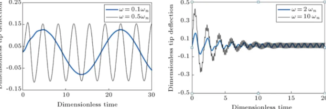
Figure 3 declares the dimensionless end deection of the 5th type of FG micro-beam versus time for dierent thermal excitation frequencies, when it is deected owing to the application of 5 [V] primal bias voltage. Hereafter, the 5th type is the reference type whenever no type is specied. As shown in Figure 3, the response amplitude of the beam, as expected, grows unboundedly when the thermal excitation frequency equals the natural frequency of the beam. Resonance phenomenon in capacitive micro beams causes an increase in the amplitude of the response. Of course, it must be noted that the electrostatic force is a displacement dependent force. Therefore, increasing the amplitude of the response can lead the struc-ture to an unstable condition through a homoclinic bifurcation [23]. However, because, in this work, results are obtained through a linearized equation, this phenomenon cannot be seen. Another point that deserves attention is that, as anticipated, when the excitation frequency is close, but not exactly equal,
Table 3. Pull-in voltages of homogenous cantilever micro-beams: comparisons with experimentally measured data. Cantilever length (m)
Pull-in voltages in proposed
model (V)
Pull-in voltage based on the
experimental observations [34], (V)
Error, (%)
75 77.43 76.2 1.6
100 43.56 43.5 0.1
125 27.88 28.1 0.7
150 19.36 19.6 1.2
175 14.23 14.5 1.9
200 10.9 10.9 0
225 8.61 9.3 7.4
to the natural frequency, the \beating" phenomenon occurrs.
Phase portraits reveal many important charac-teristics about the dynamic behavior of the system, i.e. specify that the solution of the system is stable or unstable. Figure 4(a) and (b) demonstrate the phase portrait of the 5th type of the FG micro-beam. When the thermal excitation frequency is equal to the rst natural frequency of the beam, the amplitude increases without bound as long as the tip of the beam contacts the substrate (Figure 4(a)). As mentioned earlier, in a non-linearized system, contact with the substrate will be occurred through a homoclinic bi-furcation. Figure 4(b) shows the dimensionless phase portrait of a bounded response for the 5th type of FG micro-beam when the thermal excitation frequency is 1404 kHz.
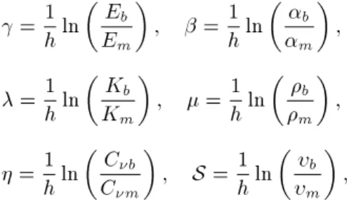
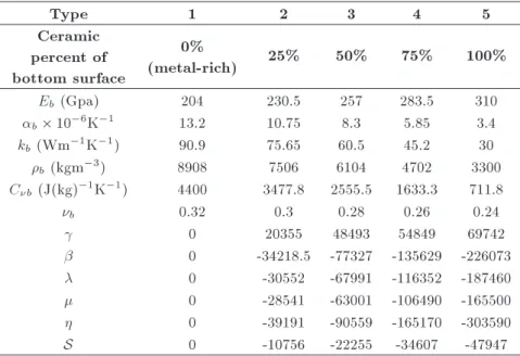
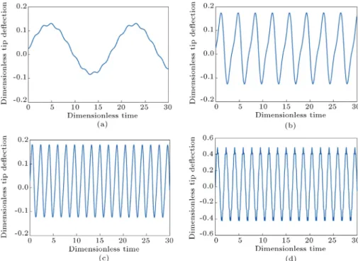
Figure 5(a)-(d) illustrate the dimensionless end deection of the 5th type of FG micro-beam versus
time when various thermal excitation frequencies are applied.
In Figure 6, the dimensionless end deection of the dierent types of FG micro-beam versus time is shown. From this data, it can be resulted that FG beams with lower ceramic constituent percentage, contact later with the stationary electrode. The reason is, the lower the ceramic constituent percentage of the FG micro-beam, the lower the amount of thermal moment.
As the value of the internal thermo-elastic damp-ing is small and the free vibration response can be seen in the responses for long periods of time, Fig-ures 7 and 8 present oscillatory motion, considering an external equivalent coecient of damping, such as squeeze lm damping. Figure 7 shows the time-history of the dimensionless transverse deection of the 5th type of FG micro-beam tip when the applied thermal excitation frequency is considered equal with
Figure 4. Dimensionless phase portraits: a) ! = !n; and b) ! = 140 kHz.
Figure 5. Time-history of the dimensionless transverse deection of the 5th of FG micro-beam tip: a) ! = 0:1 !n; b)
Figure 6. Time-history of the dimensionless transverse deection of dierent types of FG micro-beam tip in the resonance case (primal voltage = 5 (V)).
Figure 7. Time-history of the dimensionless transverse deection of the 5th type of FG micro-beam tip when ! = !nand various external damping coecients are
considered (primal voltage = 5 V).
the natural frequency. It is apparent from this gure that when the damping coecient is increased, the amplitude of vibration decreased.
Figure 8(a) and (b) show time-history of the dimensionless transverse deection of the 5th type of FG micro-beam tip for dierent thermal excita-tion frequencies, considering an equivalent external damping coecient (c = 0:1) with a primal bias DC
Figure 9. Time-history of the dimensionless transverse deection of the 5th type of FG micro-beam tip when dierent primal voltages are applied (! = 100 kHz).
voltage equal to 5 (V). According to Figure 8, as time passes, the free vibration response is dissipated and the FG beam is oscillated with the thermal excitation frequency and constant amplitude.
Figure 9 depicts the eect of applied bias DC voltage on the time-history response of the 5th type of FG micro-beam tip. From the gure, it can be concluded that by increasing the applied bias DC voltage, not only is the static equilibrium position of the beam raised, but also the amplitude of the response (100 kHz arbitrary thermal excitation frequency is applied.)
The eect of changing initial gap (g0) on the time
history response of the 5th type of FG micro-beam tip is presented in Figure 10. The data would seem to suggest that increasing the amount of initial gap causes a decrease in both static equilibrium position and amplitude of response. It is clear from Eq. (16) that electrostatic force will be decreased when the initial gap is increased.
Because the thermo-elastic coupling term is not usually distinguishable with the uncoupled solution for dierent materials [15], Figure 11 is given to show the time history of the dimensionless transverse deection
Figure 8. Time-history of the dimensionless transverse deection of the 5th type of FG micro-beam tip when dierent thermal excitation frequencies are applied considering arbitrary external damping coecient (c = 0:1, primal voltage = 5 V).
Figure 10. Time-history of the dimensionless transverse deection of the 5th type of FG micro-beam tip when various initial gaps are considered (! = 100 kHz).
Figure 11. Time-history of the dimensionless transverse deection of the 5th of FG micro-beam tip, the magnied coupling eect (primal voltage = 5 V and ! = 100 kHz).
of the 5th type of FG micro-beam tip when the coupling term between strain and temperature is magnied 1000 times. It is observed that the amplitude of vibration decreases with time.
Figure 12 shows the dimensionless maximum am-plitude of the 5th type of FG micro-beam, with respect to dimensionless frequency, when various voltages are applied. As mentioned previously, Figure 12 indicates that increasing the applied bias voltage causes a de-crease in the natural frequency and, on the contrary, an increase in the amplitude of vibration. Note that dimensionless frequency is introduced as ^!, and in this study, it equals ^! = !t. The magnitude of t,
considering Eq. (25), is obtained as 2:14 10 5.
Figure 13 illustrates the dimensionless time-history response for the homogenous micro-beam (metal rich) when it is deected electrostatically by 5 V bias DC voltage. For the homogenous beam, the thermal moment equation (MT) is not included, T (^t).
This dierence between the thermal moments of the FG and homogenous beams leads to dierent responses to the thermal actuation. By comparing the responses of
Figure 12. Frequency-response curves of 5th type of a FG micro-beam when various primal voltages are applied.
Figure 13. Time-history of the dimensionless transverse deection of the homogenous micro-beam tip for dierent thermal excitation frequencies (primal voltage = 5 V).
the FG and homogenous beams, it can be concluded that the vibration amplitudes of the FG beam are signicantly greater than those of the homogenous beam. This is because, in the latter, thermal moment is created only due to a small temperature gradient related to the thermo-elastic coupling eect.
c MT =K
c
MT(4)= K ~Am
N
X
i N
X
j
Gij(^t)'i(^x)
Z 1 2 1 2
j(^z)^zd^z: (56)
5. Conclusions
The objective of this paper is to present the dynamic response of an electrostatically deected capacitive FG cantilever micro-beam to harmonically varying thermal loads. Vibration is incited due to the dierent material properties of the beam constituents and the thermo-elastic coupling eect. Boundary conditions of the FG micro-beam are taken to be cantilever, with the tip to be isolated. Results describe the dynamic transverse deection and frequency response curves of the FG micro-beam. In this study, the FG micro-beam is
made of a mixture of metal and ceramic, where the thermo-mechanical properties of the FG micro-beam are all assumed to vary exponentially through the thickness. The theoretical governing coupled thermo-elastic formulations are based on the Euler-Bernoulli beam theory and innite speed of heat propagation. To solve the problem, the Galerkin formulation method is used. Results illustrate the eect of variation of bias DC voltage and changing ceramic constituent percent-age on the FG micro-beam time-history and frequency responses. The numerical calculation demonstrates that increasing the ceramic constituent percent of the beam material causes the beam tip to contact with stationary electrodes in less periods of time. This is due to increasing the dierence of the thermal expansion coecient between the FG micro-beam surfaces, which results in an increase in thermal moment. It is also shown that the vibration amplitudes of the FG micro-beam are signicantly greater than those of the homogenous beam, since, in the latter, the thermal moment is created only because of a small temperature gradient owing to the thermo-elastic coupling eect. Moreover, the eect of thermo-elastic damping on the dynamic responses of the beam is negligible.
References
1. Suresh, S. and Mortensen, A., Fundamentals of Func-tionally Graded Materials, IOM Communications Ltd, London (1998).
2. Suresh, S. and Mortensen, A. \Modeling and design of multi-layered and graded materials", Prog. Mater Sci., 42, pp. 243-251 (1997).
3. Birman, V. and Byrd, L. \Modeling and analysis of functionally graded materials and structures", ASME Journal of Applied Mechanics Reviews, 80(5) p. 195 (2007).
4. Sankar, B.V. \An elasticity solution for functionally graded beams", Compos. Sci. Technol., 61(5), pp. 689-696 (2001).
5. Sankar, B.V. and Taeng, J.T. \Thermal stresses in functionally graded beams", AIAA Journal, 40(6), pp. 1228-1232 (2002).
6. Chakraborty, A., Gopalakrishnan, S. and Reddy, J.N. \A new beam nite element for the analysis of func-tionally graded materials", Int. J. Mech. Sci., 45(3), pp. 519-539 (2003).
7. Qian, L.F. and Ching, H.K. \Static and dynamic analysis of 2D functionally graded elasticity by using meshless local Petrov-Galerkin method", Journal of the Chinese Institute of Engineers, 27(4), pp. 491-503 (2004).
8. Ching, H.K. and Yen, S.C. \Meshless local Petrov-galerkin analysis for 2D functionally graded elastic solids under mechanical and thermal loads", Compos-ites Part B, 36(3) pp. 223-240 (2005).
9. Aydogdu, M. and Taskin, V. \Free vibration analysis of functionally graded beams with simply supported edges", Mater. Des., 28(5), pp. 1651-1656 (2007). 10. Xiang, H.J amd Yang, J. \Free and forced vibration
of a laminated FGM Timoshenko beam of variable thickness under heat conduction," Composites Part B, 39(2), pp. 293-303 (2008).
11. Kapuria, S., Bhattacharyya, M. and Kumar, A.N. \Bending and free vibration response of layered func-tionally graded beams: A theoretical model and its experimental validation", Compos. Struct., 82(3), pp. 390-402 (2008).
12. Li, X.F. \A unied approach for analyzing static and dynamic behaviors of functionally graded Timoshenko and Euler-Bernoulli beams", J. Sound Vib., 318(4-5), pp. 1210-1229 (2008).
13. Pradhan, S.C. and Murmu, T. \Thermo-mechanical vi-bration of FGM sandwich beam under variable elastic foundations using dierential quadrature method", J. Sound Vib., 321(1-2), pp. 342-362 (2009).
14. Abbasi, M., Sabbaghian, M. and Eslami, M.R. \Exact closed-form solution of the dynamic coupled thermoe-lastic response of a functionally graded Timoshenko beam", J. Mech. Mater. Struct., 5(1), pp. 79-94 (2010). 15. Babaei, M.H., Abbasi, M. and Eslami, M.R. \Coupled thermo-elasticity of functionally graded beams", J. Therm. Stresses, 31(8), pp. 680-697 (2008).
16. Sina, S.A., Navazi, H.M. and Haddadpour, H. \An analytical method for free vibration analysis of func-tionally graded beams", Mater. Des., 30(3), pp. 741-747 (2009).
17. Mahi, A., Adda Bediab, E.A., Tounsib A. and Mechabb, I. \An analytical method for temperature-dependent free vibration analysis of functionally graded beams with general boundary conditions", Compos. Struct., 92(8), pp. 1877-1887 (2010). 18. Azadi, M. \Free and forced vibration analysis of FG
beam considering temperature dependency of material properties," J. Mech. Sci. Technol., 25(1), pp. 69-80 (2011).
19. Afshar, A., Abbasi, M. and Eslami, M.R. \Two-dimensional solution for coupled thermoelasticity of functionally graded beams using semi-analytical nite element method," Mech. Adv. Mater. Struct., 18(5), pp. 327-336 (2011).
20. Malekzadeh, P. and Shojaee, A. \Dynamic re-sponse of functionally graded beams under mov-ing heat source", J. Vib. Control 5, (2012), Doi: 10.1177/1077546312464990.
21. Su, H., Banerjeeb, J.R. and Cheungb, C.W. \Dynamic stiness formulation and free vibration analysis of functionally graded beams", Compos. Struct., 116, pp. 854-862 (2013).
22. Hemmatnezhad, M., Ansarib, R. and Rahim, G.H. \Large-amplitude free vibrations of functionally graded beams by means of a nite element formula-tion", Appl. Math. Modell., 37(18-19), pp. 8495-8504 (2013).
23. Younis, M.I. \Mems linear and nonlinear statics and dynamics", (2011) DOI 10.1007/978-1-4419-6020-7. 24. Soh, A.K., Sun, Y. and Fang, D. \Vibration of
microscale beam induced by laser pulse", J. Sound Vib., 311(1-2), pp. 243-253 (2008).
25. Sun, Y., Fang, D., Saka, M. and Soh, A.K. \Laser-induced vibrations of micro-beams under dierent boundary conditions", Int. J. Solids Struct., 45(7-8), pp. 1993-2013 (2008).
26. Mohammadi-Alasti, B., Rezazadeh, G., Borgheei, A.M, Minaei, S. and Habibifar, R. \On the mechanical behavior of a functionally graded micro-beam sub-jected to a thermal moment and nonlinear electro-static pressure", Compos. Struct., 93(6), pp. 1516-1525 (2011).
27. Zamanzadeh, M.R., Rezazadeh, G., Jafarsadeghi-pournaki, I. and Shabani, R. \Static and dynamic stability modeling of a capacitive FGM micro-beam in presence of temperature changes", Appl. Math. Modell., 37, pp. 6964-6978 (2013).
28. Youssef, H.M. and Elsibai, K.A. \Vibration of gold nano-beam induced by dierent types of thermal loading- A state-space approach", Nanoscale Mi-croscale Thermophys. Eng., 15(1), pp. 48-69 (2010). 29. Youssef, H.M. \Vibration of gold nanobeam with
variable thermal conductivity: State-space approach", Applied Nanoscience, 3(5), pp. 397-407 (2013). 30. Sadd, M.H., Elasticity, Theory, Applications, and
Numerics 2nd Ed. Academic Press (2009).
31. Saeedi Vahdat, A. and Rezazadeh, G. \Eects of axial and residual stresses on thermo elastic damping in capacitive micro-beam resonators," J. Franklin Inst., 348(4), pp. 622-639 (2011).
32. Lienhard, J.H., A Heat Transfer Textbook IV, Phlogis-ton Press Cambridge Massachusetts (2003).
33. Rao, S.S., Vibration of Continuous Systems, John Wiley & Sons (2007).
34. Osterberg, P.M. \Electrostatically actuated microme-chanical test structure for material property measure-ment", Ph.D. Dissertation, Massachusetts Institute of Technology (1995).
Appendix
The parametrs Q and R appeared in the text are listed below:
Q(1)kr = Z 1
0 k rd^x; Q (2) kr =
Z 1
0 i k rd^x;
Q(3)kr = Z 1
0
A1V2 k
(1 W^s)3 rd^x;
Q(4)ir = Z 1
0 'i(1)
^x2
2 rd^x;
Q(5)j =Km
h
Z 1=2
1=2^ze
h(^z+1=2)
Z 1=2
1=2e
(+)h(^z+1=2)
j(^z)d^zd^z
~ A
Z 1=2
1=2j(^z)^ze
(+)h(^z+1=2)d^z;
Q(6)ir = Z 1
0 ' 00 i ^x
2
2 rd^x;
Q(7)ir = Z 1
0
A1V2
(1 W^s)3'i(1)
^x2
2 rd^x;
Q(8) r =
Z 1
0
^x2
2 rd^x;
Q(9)j =K
B1
Z 1=2
1=2^ze
h(^z+1=2)d^z
~ Am
Z 1=2
1=2e
(+)h(^z+1=2)d^z;
Q(10) r =
Z 1
0
A1V2
(1 W^s)3^x 2
rd^x;
R(1)iq = Z 1
0 'i'qd^x;
R(2)jg = Z 1=2
1=2
k(^z)00
j +@k(^z)@^z 0j
gd^z;
R(3)iq = Z 1
0 ' 00 i'qd^x;
R(4)jg = A2
Z 1=2
1=2(k(^z)j) gd^z;
R(6)iq = Z 1
0 'i(1)'qd^x;
R(8)kq = Z 1
0 00 k'qd^x;
R(9)jg = Z 1=2
1=2( A4^z + A5)E(^z)(^z)gd^z;
R(10) q =
Z 1
R(5)jg = Z 1=2
1=2
A3
(^z)C(^z) + 2((^z) + 1)1 2(^z)
E(^z)(^z)2T 1
j(^z) A6E(^z)(^z)hm
Z 1=2
1=2e
(+)h(^z+1=2) j(^z)d^z
gd^z;
R(7)jg = Z 1=2
1=2( A4^z + A5)E(^z)(^z)Km
h
Z 1=2
1=2^ze
h(^z+1=2)
Z 1=2
1=2e
(+)h(^z+1=2)
j(^z)d^zd^z
+ ~A Z 1=2
1=2j(^z)^ze
(+)h(^z+1=2)d^z gd^z;
R(11)jg = Z 1=2
1=2
A3
(^z)C(^z)
+2((^z) + 1)1 2(^z) E(^z)(^z)2T 1
+ E(^z)(^z)[( A4^z + A5)
K( B1B + ~~ A ~Cm) A6B1]
gd^z:
Biographies
Ilgar Jafarsadeghi-pournaki was born in Khoy, West Azerbaijan, Iran, in 1986. He received his BS degree in Mechanical Engineering in Solid Mechanics from the Islamic Azad University, Khoy, Iran, in 2009,
and his MS degree in the same eld, in 2012, from the Department of Mechanical Engineering at Urmia University, Iran, where he is currently working as a research assistant. His research contributions are in the eld of vibration of MEMS and NEMS, nonlinear dynamics, non-classical continuum theories, vibration energy harvesting, vibration of beams containing smart materials and thermo-elastic damping (TED).
Ghader Rezazadeh received BS and MS degree in Mechanical Engineering from Isfahan Technical Uni-versity, Iran, in 1991, and his PhD degree in the same eld from Bauman Moscow State Technical University, Russia, in 1997. He is currently Professor of Mechanical Engineering at Urmia University, Iran. His major research interests include a broad area of topics in micro- and nano- electromechanical systems (MEMS and NEMS), with a special focus on the stability of structures, nonlinear dynamics and non-classical continuum theories.
Mohammadreza Zamanzadeh was born in Tehran, Iran, in 1983. He obtained his BS degree in Mechanical Engineering, in Solid Mechanics, from the Islamic Azad University, Khoy, Iran, in 2009, and his MS degree in the same eld from the Department of Mechanical Engineering at Urmia University, Iran, in 2012. His research interests include vibration of MEMS and NEMS, nonlinear dynamics, non-classical continuum theories, parametric oscillation, stability of structures and thermo-elastic damping (TED).
Rasool Shabani received BS, MS and PhD degrees in Mechanical Engineering from Sharif University of Tech-nology, Tehran, Iran, and is currently Associate Pro-fessor of Mechanical Engineering and Vice-Chancellor of Education of the Engineering Department at Ur-mia University, Iran. His research interests include nonlinear dynamics and chaos, nonlinear control, uid structure interactions and self-excited vibrations.