ISSN: 2252-8938 45
A Fuzzy Controller for Compensation of Voltage Sag/Swell Problems
Using Reduced Rating Dynamic Voltage Restorer
Rajesh Damaraju, S.V.N.L. Lalitha
Department of Electrical and Electronics Engineering, KL University, Vaddeswaram, Guntur A.P, India.
Article Info ABSTRACT
Article history: Received Feb 4, 2015 Revised April 7, 2015 Accepted May 8, 2015
Non linear loads are highly effected by variations in voltages. Dynamic voltage restorer is one of the most popular compensating devices due to its low cost and better performance. Usage of Park’s transformation technique effectively reduces the rating of Dynamic voltage restorer. Application of fuzzy logic controller for getting the better result is proposed in this paper. The results are verified in Matlab/Simulink environment.
Keyword:
FACTS controllers Fuzzy Inference System Parks transformation Sag/Swell
Copyright © 2015 Institute of Advanced Engineering and Science. All rights reserved. Corresponding Author:
Rajesh Damaraju,
Department of Electrical and Electronics Engineering, KL University,
Vaddeswaram, Guntur A.P, India.
1. INTRODUCTION
In the present scenario the production and distribution of electrical power is maintained continuously. In interfaced system, the electrical power system faces the problems regarding power quality such as variations in voltage or current levels and harmonics [1]-[5], finally these papers proposes the concept of conventional series reactor compensation and injection transformer methods but this methods has disadvantages i.e these methods are not compatible for high power applications for compensating the voltage sag and swell problems. Out of all these power quality problems, the variations in voltage i.e sag and swell conditions are easily occur due to fault, and utilization of sensitive loads. If these problems occur continuously then it causes the severe effect on the power system such as failure of the equipment, shut down of power plant and also creates unbalances in currents as mentioned in [6]. This problems also shows the effect on the distribution system such as consumer loads. The voltage reduction known as sag criteria, generally occurs at any instant of time, with change in amplitude from 10 – 90% of its rated value and the time duration is less than a minute. And in other case, the voltage swell is defined as an increase in rms voltage at the power with variations in magnitudes between 1.1 and 1.8 pu [8].
Generally, the problem of Voltage swell is not a severe problem as like voltage sags because they are less common in distribution systems. To protect the system from all these power quality problems, we need a unique compensating device which can compensate all the power quality problems uniquely [9]. The compensating methods presented in this paper has the following disadvantages such as these methods are not compatible for high distribution systems and if the severe fault occurs on the system these methods are not suitable for compensating the voltage sag problems. So, as per the literature survey on the power electronic based converter, the flexible ac transmission system plays a key role. Based on the circuit configurations and control capability this facts devices are classified into four types, i.e. series converter, shunt converter, series-series converter, and series-series-shunt converter [10]. Out of all four types of facts controllers the series-series converter
Reduced Rating Dynamic Voltage Restorer (DVR) & Control strategy of DVR, section 4 explains Fuzzy Logic Controller, section 5 shows Simulation diagram and results, and finally section 6 concludes the paper.
2. GRID INTERFACING SYSTEM
To protect the power system components from voltage sags and swells, the DVR plays a key role when compared with the other compensating devices. The efficiency of DVR is high and provide reliable operation [11] as compared with the basic controllers such as injection transformers, series and shunt reactors and fault limiters.
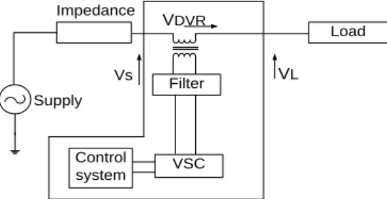
The main function of DVR is to inject extra voltage to the transmission system for regulating the voltage across load [13]. The location of dynamic voltage restorer is generally located in distribution side i.e. between distribution feeder and load. The schematic diagram of the DVR is shown in Figure 1.
Load
Filter
VSC Control
system Supply
Impedance
Vs VL
VDVR
Figure 1. Basic Structure of Dynamic Voltage Restorer.
The general configuration of the DVR mainly consists of the following components such as, 1. An boosting transformer
2. A filter for reducing harmonic 3. The battery energy Storage system 4. A Voltage Source Converter 5. DC charging circuit
6. A control diagram for controlling DVR based on reference voltages and actual load voltages with the help of PWM technique. In this a general PI controller is used for controlling the error value [14].
DVR is used for compensate the changes in voltage dynamically. The voltage generated by a forced commutated converter is to inject voltage to the line through a series transformer called as boosting transformer.
The basic operation of DVR can be explained in mainly three modes such as: one is protection mode, second one is standby mode, and third one is injection/boosting mode.
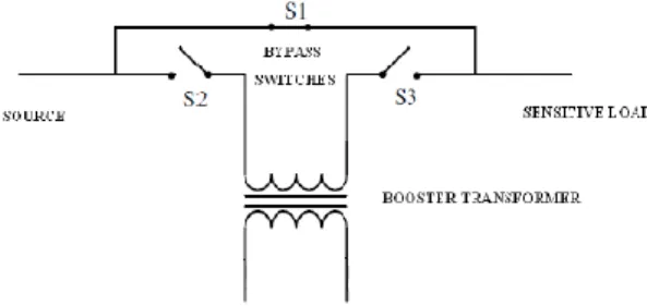
1. Protection mode: If in any situation the load current is increased more than its permissible value, due to fault condition or short circuit on load side, the dynamic voltage regulator will be isolated from the by the use of bypassing switches S1 and S2 as shown in Figure 2.
Figure 2. Protection Mode of dvr
2. Standby Mode: In case of this standby mode the boosting transformer secondary winding is short circuited, with this the DVR is unable to inject any compensating values as shown in Figure 3.
Figure 3. Standby Mode of DVR
3. Injection/Boost Mode: In this case of injection mode the transformer is called injection transformer and the DVR has the capability of injecting voltage for compensating the power quality problems. In-phase compensation method is used to compensate voltage magnitude. The compensated voltage is in phase with the sagged voltage, therefore this technique minimize the voltage injected by the DVR. This technique is shown in Figure 4, there is phase shift between the voltage before the sag and after the sag. It is recommended for the linear loads.
2.1. In-phase compensation method for dynamic voltage restorer
In-phase compensation method is a straight forward method. In this method the injected voltage is maintained in phase with the supply voltage irrespective of the load current and pre-fault conditions [15]. Generally, the phase angles between the pre-sag and load voltages are different but also it has the capability of maintaining the power quality by compensating the load voltage.
where a sensitive load is connected, under system disturbances. It will also look after the D.C. link voltage using the DC-charging unit [17].
Figure 5. Block Diagram of General DVR Circuit
3. CONTROL STRATEGY FOR DVR
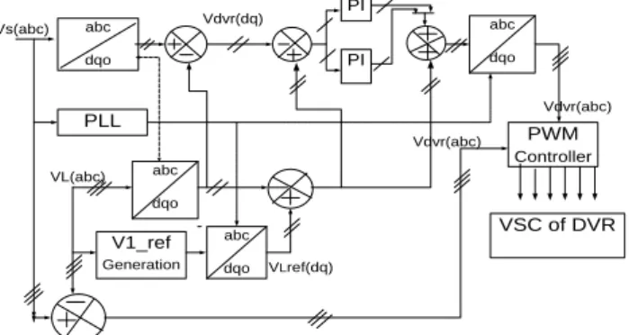
Figure 6 shows the control block diagram technique for controlling the dynamic voltage restorer. In this case the source voltage at place of point of common coupling and load voltage are considered for obtaining gate triggering pulses to converter.
abc dqo PI PI abc dqo PWM Controller PLL abc dqo V1_ref Generation abc dqo Vs(abc) VL(abc) VLref(dq) Vdvr(abc) Vdvr(abc) Vdvr(dq)
VSC of DVR
Figure 6. Control Block Diagram for DVR
Basically, the three phase load voltages are transformed to the two phase rotating reference frame using Parks transformation technique. The source voltage at the point of common coupling is also converted into direct and quadrature axis components using Parks transformation. These source and load voltages are compared and applied to PI controller. The error obtained is used for generating gate firing signals to the voltage source converter.
4. FUZZY LOGIC CONTROLLER
In the previous section, control strategy based on PI controller is discussed. But in case of PI controller, it has high settling time and has large steady state error. In order to rectify this problem, this paper proposes the application of a fuzzy logic controller (FLC). Generally, the FLC is one of the most important software based technique in adaptive methods.
As compared with previous controllers, the FLC has low settling time, low steady state errors. The operation of fuzzy controller can be explained in four steps.
L o a d Filter circuit PWM Inverter Storage unit Supply Line Impedance
V1 V2
VDVR
Vg
I
1. Fuzzification 2. Membership function 3. Rule-base formation 4. Defuzzification.
K1
d
dt k2
fuzzifi cation
Rule base
Inference mechanism
defuz zificat
ion k3
e(t)
U(t)
Figure 7. Basic Structure of Fuzzy Logic Controller
In this paper, the membership function is considered as a type in triangular membership function and method for defuzzification is considered as centroid. The error which is obtained from the comparison of reference and actual values is given to fuzzy inference engine. The input variables such as error and error rate are expressed in terms of fuzzy set with the linguistic terms VN, N, Z, P, and VP. In this type of mamdani fuzzy inference system the linguistic terms are expressed using triangular membership functions. In this paper, single input and single output fuzzy inference system is considered. The number of linguistic variables for input and output is assumed as 3. The number of rules are formed as 9. The input for the fuzzy system is represented as error of PI controller. The fuzzy rules are obtained with if-then statements. The given fuzzy inference system is a combination of single input and single output. This input is related with the logical operator AND/OR operators. AND logic gives the output as minimum value of the input and OR logic produces the output as maximum value of input.
5. SIMULATION DIAGRAM AND RESULT
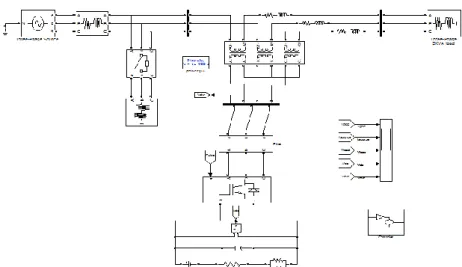
The simulation diagram for the DVR is shown in Figure 8 as shown below.
Figure 8. Simulation Diagram for Dynamic Voltage Restorer
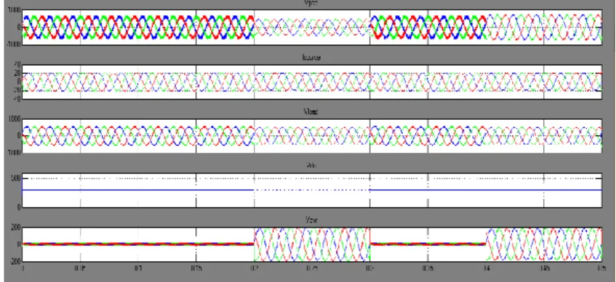
This diagram shows the connection of DVR to a transmission system and the controlling diagram for series converter. In this case study, voltage sag condition is considered during the time interval between 0.2 sec and 0.3 sec and the voltage swell condition is considered between the times 0.4 sec and 0.5 sec. It is also observed that the DVR has successfully compensated these conditions. The simulation results for the input voltage during voltage sag and swell conditions, source current, compensated load voltage, injected capacitor voltage and injected DVR voltage as shown in Figure 9 and Figure 10. This paper compares the results for both cases of PI and Fuzzy logic controller applications.
Figure 9. Simulation Results for Proposed System with PI Controller
Case 2: Simulation results of Dynamic Voltage restorer with Fuzzy controller
Figure 10. Simulation Results for Proposed System with Fuzzy Controller
Figure 9(a) shows the simulation results of single area based dynamic voltage restorer system. From this results it is observed that the sag appears in the system between the time 0.2 to 0.3 sec and swell in voltage appears at 0.4 sec, so that the dynamic voltage restorer compensate these voltage sag and swell conditions as shown in figure 9(e). Figure 9(d) shows the simulation result for dc link capacitor voltage. Comparison of the Total Harmonic Distortion of PI and FLC are shown in Figure 11 and Figure 12.
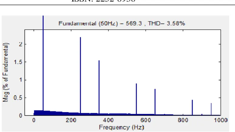
Figure 12. THD for Voltage with Fuzzy Controller
Figure 11 and 12 shows the outputs of the total harmonic distortions of the output voltage of the single area system with dynamic voltage restorer by considering conventional PI and fuzzy logic controllers. Out of these controllers the fuzzy controller get good THD as compared with the conventional controllers. The THD for voltage with PI controller is 8.95% and FLC is 3.58%. It shows that FLC is better than PI controller.
6. CONCLUSION
This paper discusses the concept of operation of reduced rating DVR with a new control strategy along with the In-phase compensation technique for compensating the power quality problems. The conventional PI based control technique is compared with proposed Fuzzy logic controller. Total harmonic distortion is compared with both PI controller and Fuzzy controller and it shows that FLC has fast response, low steady state error and less settling time.
REFERENCES
[1] Pychadathil Jayaprakash, Member, IEEE, Bhim Singh, Fellow, IEEE, DP Kothari, Fellow, IEEE, Ambrish Chandra, Senior Member, IEEE, Kamal Al-Haddad, Fellow, and IEEE presented a paper on Control of Reduced-Rating Dynamic Voltage Restorer with a Battery Energy Storage System at IEEE TRANSACTIONS ON INDUSTRY APPLICATIONS. 2014; 50(2).
[2] SS Choi, TX Wang, DM Vilathgamuwa. A series compensator with fault current limiting function. IEEE Trans. Power Del. 2005; 20(3): 2248–2256.
[3] B Delfino, F Fornari, R Procopio. An effective SSC control scheme for voltage sag compensation. IEEE Trans. Power Del. 2005; 20(3): 2100–2107.
[4] F Badrkhani Ajaei, S Afsharnia, A Kahrobaeian, S Farhangi. A fast and effective control scheme for the dynamic voltage restorer. IEEE Trans. Power Del. 2011 26(4): 2398–2406.
[5] P Roncero-Sánchez, E Acha, JE Ortega-Calderon, V Feliu, A García-Cerrada. A versatile control scheme for a dynamic voltage re-storer for power-quality improvement. IEEE Trans. Power Del., 2009; 24(1): 277–284.
[6] Lu, Weixing, Boon-Teck Ooi. Optimal Acquisition and Aggregation of Offshore wind Power by Multiterminal Voltage-Source HVDC. IEEE Trans. Power Delivery. 2003; 18: 201–206.
[7] P Boonchiam, N Mithulananthan. Understanding of Dynamic Voltage Restorers through MATLAB Simulation.
Thammast Int. J.Sc. Tech. 2006; 11(3).
[8] DM Vilathgamuwa, AADR Perera, SS Choi. Performance improvement of the dynamic voltage restorer with closed-loop load voltage and current-mode control. IEEE Trans.Power. Electron. 2002; 17(5): 824–834.
[9] Weimers, L. A New Technology for a Better Environment. Power Engineering Review, IEEE. 1998; 18(8).
[10] Schettler F, Huang H, Christl N. HVDC transmission systems using voltage source converters – design and applications. IEEE Power Engineering Society Summer Meeting, July 2000.
[11] J Jeong, B Han. Development of Line-Interactive Dynamic Voltage Restorer with Hybrid Sag Detection. 2010
IEEE
[12] B Bae, J Jeong. Novel Sag Detection Method for Line-Interactive Dynamic Voltage Restorer. IEEE transactions on power delivery. 2010; 25(2).
[13] Usha Rani P, DrS Rama Reddy. Voltage Sag/Swell Compensation in an Interline Dynamic Voltage Restorer.
PROCEEDINGS TO ICETECT.
[14] Alfonso Parreno Torres, Pedro Roncero-S´anchez. Generalized Proportional-Integral Control for Voltage-Sag Compensation in Dynamic Voltage Restorers. 2011 IEEE.