JEEECCS, Volume 6, Issue 20, pages 1-6, 2020
An Improved Robotic Control System Using
Wireless Fidelity Network
Promise Elechi
Department of Electrical Engineering Rivers State University
Port Harcourt, Nigeria [email protected]
Sunny Orike and Chinedum E. Emmanuel
Department of Electrical Engineering Rivers State University
Port Harcourt, Nigeria [email protected]
Abstract – In this work, Wireless Fidelity Technology commonly referred to as Wi-Fi was used for robotic control. The existing systems are mainly web based. Thus; they require some form of internet connections to operate effectively. This possesses a major challenge to developing countries like Nigeria with slow and unevenly distributed internet access. This project was carried out using the lolin NodeMCU version 1.0 (esp8266 e12 controller), two 12v dc motors, L293 motor driver and a 12v dc voltage source. Proteus and Matlab software were used to design the circuit and analyze the signal respectively. Control of the robot was based on a Wi-Fi hotspot network created by the robot system. Control of the robot was achieved without the use of a web server/computer but through an android based application developed on MIT app developer platform. This allows flexibility and security in the control of the robot as any android phone having the required application could access the system via its Wi-Fi network to actuate commands.
Keywords- Wi-Fi; Robot Control; Web Server; Communication; Mobile Phone; NodeMCU.
I. INTRODUCTION
A. Background of the Study
Robots are important in our world today. Their applications are far reaching and encompass a variety of different missions. They are used in the manufacturing industry to perform repetitive or difficult tasks, in the military to travel and operate in dangerous areas, and in the medical industry to assist in procedures [1]. There are a multitude of different situations where the use of a robot is a necessity, such as navigating hazardous conditions and environments where a human would be incapable of surviving or performing jobs that a human is unable to achieve without assistance. These robots can be either operated through the use of a remote-control system which in most cases is in the form of a console, or can be completely autonomous system, capable of operating without any user input to accomplish a set of tasks [1].
The fields of communication and robotics are closely entangled. This is due to the massive influence communication has in the field of robotics and control. Modern robots and other control systems rely enormously on various forms of communication protocols to operate effectively and to provide feedback to the operator or the base station. Various communication technologies are being adopted for
several robotics and control applications. One of such technology is the Wireless Fidelity technology.
Wi-Fi networks are supported by all modern operating system, most advanced game consoles and laptops, many printers and other peripherals. Wi-Fi connection cannot only be used in internet connection but it can be used for several other wireless control applications such as the control of home appliances, robot control, and drone control.
In this study, a Wi-Fi communication network which is independent of a web server would be use in robot control. This will be achieved through ESP8266 Wi-Fi module embedded with Node microcontroller unit, a L293 motor driver, 12V dc battery and 12V dc motors.
B. Review of Robot Control System
Over the years, several attempts have been made to control robotic systems using Wi-Fi. In the work of [2] a Wireless Fidelity Network Controlled Robot using a Website, Android Application, and Simple Hand Gestures was developed. In this work, a CC3000 Wi-Fi module with an in-built ARM CORTEX M3 STM32F103CBT6 microcontroller was used. The system consists of a 12V battery, a robot chassis with four 12V dc motors, and an L293 motor driver. Control of the robot was achieved using a web browser.
According to [3] a metal detection robot using RF technology was developed. The robot was made up of a metal indicator circuit which was connected to a control console to alert the operator of the presence of a suspected metallic object in the ground. They made use of the 8051 Atmel microcontroller, an RF transmitter and receiver module, push buttons for sending commands to the robot and dc motors. Owing to the use of the NRF24L10 RF module, control of the robot could be carried out from a range of up to 200m.
According to [5] an RF based pick and place robot was developed. This system was developed using amplitude shifting keying (ASK) and a 433MHz RF transmitter. A HT12E IC is used in receiving the address and control bits in the form of parallel data. The remote made use of eight switches. These switches were used in controlling the locomotion of the robot. Commands are sent by the operator from the transmitter using the switch keys. When any switch key is pressed, a data line is grounded and a low signal sent to the receiver. The receiver interprets this signal and performs an assigned actuation on the robot. A 5V DC battery was used in driving this circuit.
According to [6] that worked on the simulation of a robotic car controlled using the ESP8266 Wi-Fi module. Their design was developed such that a Laptop, a Wi-Fi module and a smart phone all have to be connected to a single Wide Local Area Network (WLAN). The ESP8266 registers an IP address. The registered IP address is written on a web browser and the control of the robot is carried out through from the web page. Since control of the robot was based solely on a web browser, a laptop is always required in order to control the robot.
According to [7] a Wi-Fi controlled robot was developed. The system was achieved using an Arduino microcontroller, an ESP8266 and an HTML interface for controlling the rover. This robot was designed to send live feeds via a webpage which can be viewed by the operator. A major drawback of this system was that it was only able to send still pictures as the microcontroller used did not support video streaming. The system was also dependent on a web browser to be controlled.
According to [8] a Wi-Fi robot using the NodeMCU, a Wi-Fi module, an Arduino microcontroller, an L293D motor driver, a 12V dc battery and two electric motors was constructed. The system was designed such that the NodeMCU placed on the robot serves as the receiver and the Arduino microcontroller connected to a Wi-Fi serving as the transmitter. The NodeMCU generates the Wi-Fi network. Commands are sent to the robot via joy sticks. The NodeMCU receives these commands and perform the corresponding actuation of the robot wheels, controlling the robot navigation.
All the reviewed works showed that communications and commands can be established through wireless fidelity network and no attempt has been made in controlling of robot using Wireless Fidelity network, without the use of a web server (Internet connection) or a host computer. These have greatly contributed to the high cost of Wi-Fi robots. This study seeks to address these challenges by developing a Wi-Fi robot control which will not require a web server (Internet connection) or a host computer to operate. This robot is to be operated and controlled from a Smartphone (master controller) using the IP Address of the robot‟s Wi-Fi module
C. Wireless Communication
According to [9] wireless communication was introduced in the 19th century and wireless communication technology has developed over the
subsequent years. It is one of the most important mediums of transmission of information from one device to another device. In this technology, the information can be transmitted through the air without requiring any cable or wires or other electronic conductors by using electromagnetic waves like IR, RF and Satellite [9]. In this present day, the wireless communication technologies are found in variety of wireless communication devices and technologies ranging from smart phones to computers. Different types of wireless communication include communication satellite, Wi-Fi, Bluetooth, broadcast radio, microwave and so on. Wi-Fi is a low power wireless communication that is used by various electronics device [9].
D. Path loss
Path Loss is commonly used in wireless communications and signal propagation. It is the reduction in the power density of an electromagnetic wave as it propagates through space [11]. Path loss is a major component in the analysis and design of the link budget of a telecommunication system [10]. Path loss can be caused by many factors such as reflection, diffraction, refraction, free space loss, aperture medium coupling loss, and absorption. It is also influenced by terrain contours, environment such as rural, urban, vegetation and foliage; propagation medium such as moist or dry air [11].
II. MATERIALSANDMETHOD
A. Materials
The communication network established consists of two parts, transmitter and receiver. The transmitter consists of smart-phone being used to control the robot (receiver). The communication channel was analyzed using „Matlab‟ software, to see what happens between the transmitter and the receiver. The circuit design was done using Proteus. Therefore, the followings materials are needed for the development of Wi-Fi robotic control system.
1. Controller (NodeMCU)
2. Resistors
3. Motor driver (L293)
4. 12V DC Motor
5. 12V battery source
6. Voltage regulator
B. Program Development
The intelligence which controls the robot is developed on two platforms. Firstly, the receiver program is developed which is the controller. This is done using the Arduino IDE 1.8.6 kit. This is due to its compatibility with the NodeMCU. In programming the NodeMCU on the Arduino IDE, the ESP8266 board is first installed. This is done by:
1. Opening the Preference windows on the Arduino IDE
sp8266com_index.jsoninto" into Additional Board Manager URLs field
3. Open Boards Manager from Tools > Board interface and find ESP8266 platform
4. Click the latest version from a drop-down box and click the install button
5. Then select the ESP8266 board from Tools > Board menu after its installation
A program is then uploaded to the ESP8266 (NodeMCU) in order to obtain its IP address. This is done by using the serial monitor on the Arduino IDE and the IP address is set on the transmitter for the Wi-Fi connection. This is done in order to enable the robot to be connected with only the transmitter. The program is designed such that, the NodeMCU receives commands from the transmitter and thus performs an action which is ascribed to the command received. The written programs are done. When arrow key UP is pressed on the cell phone, a hexadecimal command is sent to the NodeMCU. This command when received instructs the robot wheels to move forward. A similar actuation is performed when arrow key DOWN, LEFT and RIGHT.
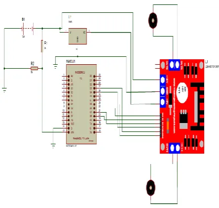
The circuit diagram showing the connection of the NodeMCU to the dc motor drivers and the battery connections is given in the figure 1. The software which governs the transmitter is developed in the form of an android application. This application is developed using the easy to use MIT APP Developer platform. The GUI is developed to contain 8 Eight Arrow keys and a speed control slide. The corresponding functions are assigned to these keys taking into consideration the pin connection of the NodeMCU to the robot wheels. A tab is created to allow for the IP Address of the NodeMCU to be added, and the communication is achieved smoothly. The diagram in figure 2 and figure 3 illustrates the flowchart of the transmitter unit and the receiver unit respectively.
Figure 1Wireless Fidelity Robot Circuit Design
Figure 2: Transmitter Flowchart
Figure 3: Receiver Flowchart Star t
Setup Phone as Transmitter
Read buttons pressed
If Button Send F
Send B
Send L
Send R
Send I
Send G
Send H
Send J
End EN
No Yes
L
Start
Setup IP Address one as
Read Data Received
If Data F
Move Forward
B
R
I
G
H
J Move
back
Move Left
Move Right
Forward Right
Forward Left SEND Go Back
Right
Go Back Left
End EN
III.ROBOT CONTROL
A. Control Range
The frequency band of Wi-Fi is 2.4GHz and 5.0GHz. Therefore, in the design of the Wi-Fi control robot, a suitable device within this Wi-Fi frequency band is chosen. This device acts as the Wi-Fi router/host, enabling the robot to be controlled remotely. The control range is 20 meters.For the purpose of this work, an ESP8266 Lolin NodeMCU is used. This device transmits Wi-Fi at a frequency of 2.4GHz.
The IP Address of the NodeMCU which is the Wi-Fi hotspot in this work is obtained from the controller on serial monitor of the Arduino Integrated Development Environment (IDE). When the Serial monitor is called, the IP address was found to be 192.168.4.2. The IP address and the ssid declared in the computer program enable the device to be easily identified and connected to by the android phone controller. The Wi-Fi robot is observed to create a Wi-Fi hotspot network when powered, with the name of the network corresponding to the ssid declared in the program.
The time interval between sending and reception of control from the smart phone to the robot is obtained from the Arduino IDE serial monitor display. This is done by adding a line of code to check for signal and the time taken for the signal to be received.
B. Communication Channel
The communication channel shows that the wireless transmitter is working according to defined standards for purity of emissions. The effects of over the air transmission and display signal strength is simulated and shown. The signal response between the transmitted waveform and received waveform for a distance of 10m is shown in figure 5. The “before” and “after” represent transmitted waveform and received waveform respectively. Contact the author for the written codes which runs the wireless communication channels. The vertical axis represents the signal strength and the horizontal represents the frequency. The signal is generated at -20dBm which is equivalent as 0.1mw and transmits at a high signal strength of 0dBm which is equivalent as 1mw. It can be clearly seen in figure 5, that the free space path loss accounts for the slight separation of the signal strength between the transmitted waveform (“before”) and received waveform (“after”) as it passes through the channel. Thus, the path loss results from the specified transmitter-to-receiver distance of 10m and also the effects of the signal attenuations are observed as the signal passes through the channel. The block diagram of the communication flow is shown in figure 4. The mobile phone sends the commands via the wireless fidelity network. NodeMCU (ESP8266) receives the signals and sends corresponding commands to the motor driver (L293) which performs the actions on the robot motors.
Figure 4: Block Diagram of Communication Flow
S
ig
n
al
S
tr
en
g
th
(
d
B
m
)
Figure 5:Spectrum Analyzer at 10m Distance
IV.CONCLUSIONANDRECOMMENDATION
A. conclusion
In this work, a wireless fidelity robot control was developed using the necessary materials listed in the above section. Control of the robot is based on a Wi-Fi hotspot created by the system. The control of the robot was achieved at the speed of 112600bps without the use of a web server but through an android application developed on MIT App developer platform. This allowed flexibility and security in control of the device. The developed projects showed that a communication between a robotic device and controlling device is achieved via a mobile phone with the readily available Wi-Fi network.
This work has shown the robotic engineers to consider a new steps and procedures in developing a communication system in robotic systems. The communication is stable and effective, as new model developed. This was achieved via wireless fidelity communication network, by identification of different electronics components relevant in the device and a control program for the device is developed. Proteus and Matlab software were deploy to design the robot circuit and analyzed the communication channel which displays its effectiveness respectively.
Left Motor
L29 3
NodeMCU
Right Motor
B. Recommendation
This research has presented an improved robotic control system using wireless fidelity network the system developed in this work was able to satisfy the intended aim and objectives of the study, there are improvements that could be made in subsequent studies on the system. Some of these improvements are:
1. The robot should be equipped with cameras and robotic arms so as to be applied in geological, environmental, mining and military operations.
2. Control of the robot via buttons on the android application interface should be replaced by the use of the accelerometer and gyroscope in the android phone. This would further simplify the control of the robot.
3. This system should be applied in control of machinery such as forklifts, conveyor belt drives, pump operation and drills, with an android application developed to match the required use.
4. This system should be applied for home automation purposes.
REFERENCES
[1] G. Nguyen, T., Slonaker, J., Kadous, “Semi-Autonomous Wireless Controlled Robot”. Capston Senior Design Project.
Indiana University Purdue University Fort Wayne. pp. 4-12, 2012.
[2] M. Adarsh, D. Mosam, N.M. Lakshmi, & N.M. Vishnu, “Wireless Network Controlled Robot using a Website, Android Application or Simple Hand Gestures”. Journal of Computer Networks, vol. 3, no. 1, pp. 1-5, 2019.
[3] V. Battala & N.K.K Ganesh, “RF Based Metal Detecting Robot”. International Journal of Innovative Technologies, vol. 3, no. 11, Pp. 2070-2074, 2015.
[4] S. Pooja, S. Renu, & R. Shubham, “A Review on RF based Fire Extinguishing Robot”. Imperial Journal of Interdisciplinary Research (IJIR), vol. 2, no. 7, pp. 372-375, 2016.
[5] C.K. Kalpana, M. Sirisha, P.T. Vishnu & N. Charanya, “RF Based Pick and Place Robot. IOSR Journal of Electronics and Communication Engineering (IOSR-JECE), vol. 12, no. 3, pp. 34-38, 2017.
[6] K. Karthikeyan, K. Mutthu, N. Nanthish, R. Rahesh, V.V. Vineeth, “Simulation of Robotic Car Controlled using Wi-Fi Module ESP8266”. International Journal of Innovative Research in Science, Engineering and Technology, vol. 6, no. 4, pp. 162-165, 2017.
[7] K. Bharath, A.D. Rashmi, S. Sourav & K. Saravanakumar, “Wi-Fi Controlled Rover”. International Journal of Trend in Research and Development (IJTRD), pp. 36-37, 2017. [8] K.M. Raj, “Wi-Fi Control Robot Using Node MCU”.
International Journal of Engineering Development and Research, vol. 6, no. 2, pp. 325-328, 2018.
[9] http://www.elprocus.com. Visited on 07/02/2020.
[10] A.I. Idim, & F.I. Anyasi, “Determination of Building Penetration Loss of GSM Signals”, Journal of Electronics and Communication Engineering, vol. 9, No. 5, pp. 1-5, 2014. [11] P. Elechi, F.O Edeko & J.O. Egwaile, “Relative Permittivity