Superlight inverse Doppler effect
The MIT Faculty has made this article openly available. Please share how this access benefits you. Your story matters.
Citation Shi, Xihang et al. “Superlight Inverse Doppler Effect.” Nature Physics 14, 10 (July 9, 2018): 1001–1005. © 2018 the Authors As Published http://dx.doi.org/10.1038/S41567-018-0209-6
Publisher Springer Nature America, Inc
Version Original manuscript
Citable link https://hdl.handle.net/1721.1/124952
Terms of Use Article is made available in accordance with the publisher's policy and may be subject to US copyright law. Please refer to the publisher's site for terms of use.
1
Superlight inverse Doppler effect
Xihang Shi1†, Xiao Lin1†*, Ido Kaminer2*, Fei Gao1, Zhaoju Yang1, John D. Joannopoulos2, Marin Soljačić2 & Baile Zhang1,3*
1Division of Physics and Applied Physics, School of Physical and Mathematical Sciences, Nanyang Technological University, Singapore 637371, Singapore.
2Department of Physics, Massachusetts Institute of Technology, Cambridge, MA 02139, USA. 3Centre for Disruptive Photonic Technologies, Nanyang Technological University, Singapore
637371, Singapore.
†These authors contributed equally to this work.
*Corresponding authors: [email protected]; [email protected]; [email protected]
There is a century-old tenet [1, 2] that the inverse Doppler frequency shift of light [3-13] is impossible in homogeneous systems with a positive refractive index. Here we break this long-held tenet by predicting a new kind of Doppler effect of light inside the Cherenkov cone. Ever since the classic work of Ginzburg and Frank, it has been known that a superlight (i.e., superluminal) normal Doppler effect [14-18] appears inside the Cherenkov cone when the velocity of the source 𝒗 is larger than the phase velocity of light 𝒗𝐩. By further developing their theory we discover that an inverse Doppler frequency shift will arise when 𝒗 > 𝟐𝒗𝐩. We denote this as the superlight inverse Doppler effect. Moreover, we show that the superlight inverse Doppler effect can be spatially separated from the other Doppler effects by using highly squeezed polaritons (such as graphene plasmons), which may facilitate the experimental observation.
2
The Doppler effect, as a well-known phenomenon of motion-induced frequency shift, is one of the most fundamental mechanisms in physics and has vast applicationsin fields as varied as weather and aircraft radars, satellite global positioning systems, blood flow measurement in unborn fetal vessels, laser vibrometry, and the detection of extrasolar planets [1]. It occurs whenever the source and the observer move relative to each other. For the conventional Doppler frequency shift, the received frequency is higher (lower) compared to the emitted frequency during the approach (recession). In 1843, Christian Doppler propounded the conventional Doppler effect, first in relation to sound, and then to light [1, 2]. Since then, it is believed that the counterintuitive inverse Doppler frequency shift of light [2], where the sign of the frequency shift is opposite to that of the conventional Doppler frequency shift, cannot occur in homogeneous systems with a positive refractive index. In 1968, Victor Veselago predicted the inverse Doppler effect (with the inverse Doppler frequency shift) in systems with a negative refractive index [3-7]. Recently, more ways were proposed to realize the inverse Doppler effect, ranging from the use of shock waves [8-11] to the use of periodic structures [12, 13], but they all involved strongly inhomogeneous systems.
Here we find that it is indeed possible to create the inverse Doppler frequency shift in homogeneous systems with a positive refractive index inside the Cherenkov cone, as long as the radiation source moves with a velocity 𝑣 larger than twice the phase velocity 𝑣pof light, i.e., 𝑣 > 2𝑣p. We denote this new phenomenon as the superlight inverse Doppler effect, which breaks the above century-old belief. The superlight inverse Doppler effect is different from the superlight normal Doppler effect [14-18], which, firstly studied by V. L. Ginzburg and I. M. Frank (GF) in 1947, emerges when 𝑣 > 𝑣p. While their theory predicted the superlight normal Doppler effect inside the Cherenkov cone, we reveal that the Doppler effects inside the Cherenkov cone can be
3
divided into two categories, i.e., the superlight normal and superlight inverse Doppler effects. Therefore, our finding further develops the GF theory of the superlight normal Doppler effect.
For conceptual demonstration, we begin with the derivation of various Doppler effects of light. Consider that a radiation source (such as a point source with a dipole moment of 𝑃̅(𝑟̅′, 𝑡′) = 𝑅𝑒{𝑥̂𝑒−𝑖𝜔0𝑡′}δ(𝑟̅′)) moves in a system with a positive refractive index 𝑛 (𝑛 > 0) and has a natural angular frequency of 𝜔0 (𝜔0 > 0) in the moving source frame. After applying the plane wave expansion [19], the frequency and wavevector in the two different frames (i.e., the lab frame and the moving source frame) can be directly linked through the Lorentz transformation [20], i.e.,
[ 𝑘𝜔/𝑐̅ ] = [ 𝛼̿ +𝛾𝛽̅
+𝛾𝛽̅ 𝛾 ] [ 𝑘
̅′
𝜔′/𝑐] (1)
In equation (1), 𝑘̅ = 𝑥̂𝑘𝑥+ 𝑦̂𝑘𝑦+ 𝑧̂𝑘𝑧 (𝑘̅′= 𝑥̂𝑘𝑥′ + 𝑦̂𝑘𝑦′ + 𝑧̂𝑘𝑧′) and 𝜔 (𝜔′= 𝜔0) are the wavevector and the frequency in the lab frame (the moving source frame), respectively; 𝑣̅ = +𝑧̂𝑣 is the velocity of the source, with its normalized form being 𝛽̅ = 𝑣̅/𝑐; 𝛾 = (1 − 𝛽2)−1/2 is the Lorentz factor; finally, we use the definition 𝛼̿ = 𝐼̿ + (𝛾 − 1)𝛽̅𝛽̅𝛽2, with 𝐼̿ being the unity dyad. From the Lorentz transformation,
𝜔 = 𝛾𝜔0+ 𝛾𝑣𝑘𝑧′ (2)
𝑘𝑧 = 𝛾𝑣𝑐𝜔𝑐0+ 𝛾𝑘𝑧′ (3)
In equation (2), 𝑘𝑧′ ∈ (−∞, +∞), and the positive (negative) value of 𝑘
𝑧′ represents the generated waves propagating along the +𝑧̂ (−𝑧̂) direction in the source static frame. Since 𝜔 − 𝛾𝜔0 is proportional to 𝑘𝑧′, one also has 𝜔 ∈ (−∞, +∞), and has 𝜔 < 0 (𝜔 > 0) when 𝑘𝑧′ < −𝜔0/𝑣 (𝑘𝑧′ > −𝜔0/𝑣). By combining equations (2-3), 𝑘𝑧= 𝜔−𝜔𝑣0/𝛾 is derived. With the knowledge of
4
𝑘𝑧 = 𝑛𝜔𝑐𝑐𝑜𝑠𝜃, where 𝜃 is the angle between the velocityof the source and the wavevector 𝑘̅ of the emitted photon (see Fig. 1), one can further express various Doppler effects of light in the following ordinary way
𝑛𝑣𝑐𝜔𝑐𝑜𝑠𝜃 = 𝜔 − 𝜔0/𝛾 (4)
Five radiation cases can be distinguished from equation (4), where the crucial factor that determines the type of the Doppler effect is the ratio between the velocity of the source and the 𝑧 -component of the phase velocity (𝑣p = 𝑐/𝑛) of light, i.e., 𝑛𝑣𝑐𝑐𝑜𝑠𝜃.
Case 1 - When 𝑛𝑣𝑐𝑐𝑜𝑠 𝜃 = 1, equation (4) is valid only if 𝜔0 = 0. This corresponds to the well-known Cherenkov radiation [20], where the Cherenkov cone is denoted in Fig. 1.
Case 2 - When 𝑛𝑣𝑐𝑐𝑜𝑠 𝜃 < 1, equation (4) is satisfied only for 𝜔 > 0, and one has 𝜔 = 𝜔0/𝛾
1−𝑛𝑣𝑐𝑐𝑜𝑠 𝜃, 𝑛 𝑣
𝑐𝑐𝑜𝑠 𝜃 < 1 (5)
When the source moves towards (away from) the observer, i.e., 𝜃 < 90o (𝜃 > 90o), one has 𝜔 > 𝜔0/𝛾 (ω < 𝜔0/𝛾), where the appearance of 𝛾 is due to the time dilation [20]. This corresponds to the conventional Doppler effect of light; see Fig. 1a.
When 𝑛𝑣𝑐𝑐𝑜𝑠 𝜃 > 1, equation (4) is satisfied only for 𝜔 < 0. As emphasized in the GF theory [14-16], having both frequencies 𝜔0 and 𝜔 positive (see equation (5)) occurs if the source passes from an upper energy level to a lower one during the process of emission, i.e., the energy ℏ𝜔 of the emitted photon is supplied from both the source excitation energy ℏ𝜔0 and its kinetic energy. However, having 𝜔0 and 𝜔 of opposite signs (see equations (6,7) below) occurs if the source becomes excited by passing from a lower energy level to an upper one during the emission
5
process, i.e., the kinetic energy of the source supplies both the energy of the emitted photon ℏ|𝜔| and the excitation energy ℏ𝜔0. We note that a similar transition between positive frequency and negative frequency has also been studied in other fields, such as negative refraction [21].
Cases 3 - When 2 > 𝑛𝑣𝑐𝑐𝑜𝑠 𝜃 > 1, from equation (4), one has |𝜔| = 𝜔0/𝛾
𝑛𝑣𝑐𝑐𝑜𝑠 𝜃−1> 𝜔0/𝛾, 2 > 𝑛 𝑣
𝑐𝑐𝑜𝑠 𝜃 > 1 (6) This is in accordance with the GF theory [14, 15] of the superlight normal Doppler effect (see Fig. 1b). The value of |𝜔| in the superlight normal Doppler effect increases with the value of 𝜃 and becomes infinity at the Cherenkov cone if the dispersion of refractive index 𝑛 is neglected. This is in stark contrast from the conventional Doppler effect, where the value of 𝜔 decreases with the value of 𝜃 (see equation (5)). Because of these differences from the conventional Doppler effect, the superlight normal Doppler effect is also denoted as the anomalous Doppler effect in some of the literature [16-18].
Case 4 - When 𝑛𝑣𝑐𝑐𝑜𝑠 𝜃 = 2, from equation (4), this leads simply to |ω| = 𝜔0/𝛾. Case 5 - When 𝑛𝑣𝑐𝑐𝑜𝑠 𝜃 > 2, from equation (4), one has
|𝜔| = 𝜔0/𝛾
𝑛𝑣𝑐𝑐𝑜𝑠 𝜃−1< 𝜔0/𝛾, 𝑛 𝑣
𝑐𝑐𝑜𝑠 𝜃 > 2 (7)
This corresponds to the superlight inverse Doppler effect (see Fig. 1c). The condition for its occurrence is 𝑣 > 2𝑐/𝑛 and the value of |𝜔| increases with the value of 𝜃. The superlight inverse Doppler effect in equation (7) is different from the superlight normal Doppler effect in equation (6), where the former has |𝜔| < 𝜔0/𝛾 while the latter has |𝜔| > 𝜔0/𝛾. Therefore, equations (6-7) describe two different types of Doppler frequency shifts inside the Cherenkov cone. The superlight
6
inverse Doppler effect is a new Doppler phenomenon of light, and to our knowledge has never been discussed before. In addition, since the condition of 𝑛𝑣𝑐𝑐𝑜𝑠 𝜃 > 1 is possible only for 𝜃 < 90o, one always has 𝜃 < 90ofor the superlight normal and superlight inverse Doppler effects; see Fig. 1.
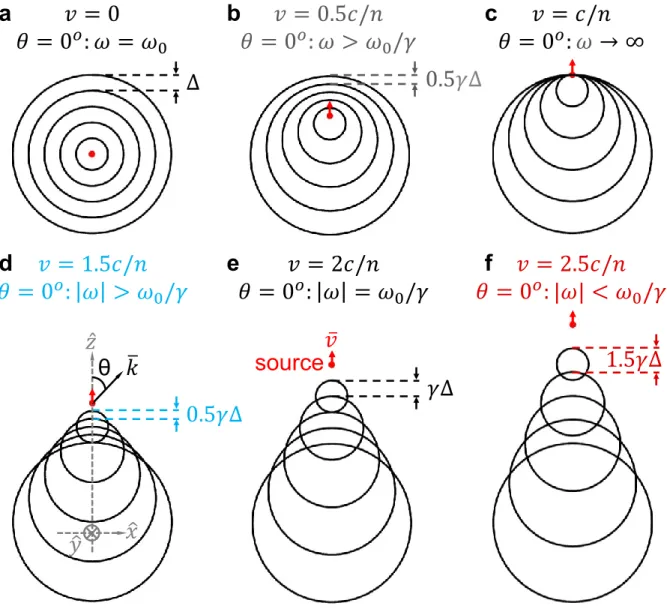
Figure 2 schematically shows the difference between the different Doppler effects in the time domain, illustrated by a cross section cut in space, marking multiple phase-fronts that are equally-distributed in time. For the simplicity of conceptual demonstration, Fig. 2 also notes the Doppler-shifted wavelength along 𝜃 = 0o (i.e., 𝑘̅ and 𝑣̅ are in the same direction). There, both the conventional and superlight normal Doppler effects (i.e., when 𝑣 < 2𝑐/𝑛) have the distance between successive wave fronts reduced, so the waves bunch together (Fig. 2a-e); in contrast, the superlight inverse Doppler effect (i.e., when 𝑣 > 2𝑐/𝑛) has the distance between successive wave fronts enlarged, so the waves spread out ( Fig. 2f). This shows a clear difference between the superlight inverse Doppler effect and the two other kinds of Doppler effect. Figure 2 also highlights a clear difference between the conventional Doppler effect and the two superlight Doppler effects: at 𝜃 = 0o, for the conventional Doppler effect (i.e., when 𝑣 < 𝑐/𝑛), the observer first receives the wave front emitted at an earlier time (Fig. 2b); however, for the superlight normal and superlight inverse Doppler effects (i.e., when 𝑣 > 𝑐/𝑛), the observer first receives the wave front emitted at a later time (Fig. 2d-f), corresponding to 𝜔 < 0 in equations (6,7).
In order to illustrate the occurrence of the superlight inverse Doppler effect, figure 3 shows various Doppler effects of highly squeezed polaritons. The high effective refractive index of such polaritons [22-24] enables the superlight inverse Doppler effect to occur with a small value of 𝑣 (due to the condition of its occurrence 𝑣 > 2𝑐/𝑛). As an example, Fig. 3 uses the surface plasmon
7
polaritons (SPP) in graphene to demonstrate the superlight inverse Doppler effect at a small value of 𝑣. Assume that the source is a dipole with𝜔0/2𝜋 = 10 THz, moving parallel to a graphene monolayer; the graphene has a chemical potential of 0.15 eV and a relaxation time of 0.3 ps. Then graphene plasmons have an effective refractive index 𝑛 = 𝑘spp
|𝜔|/𝑐 = 19 at |𝜔|/2𝜋 = 10 THz, where 𝑘̅spp = 𝑥̂𝑘𝑥+ 𝑧̂𝑘𝑧 (𝑘spp = |𝑘̅spp|) is the plasmonic wavevector parallel to the graphene plane. Using this wavevector, all the Doppler effects for graphene plasmons can be described by a single equation [25]
|𝜔| ± 𝜔0⁄ = 𝑘𝛾 spp𝑣cos𝜃 (8)
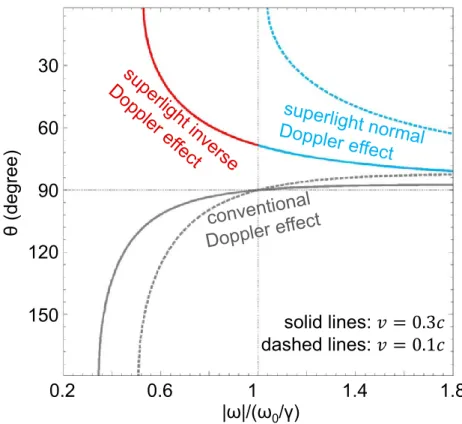
where 𝜃 is the angle between 𝑣̅ and 𝑘̅spp. When the minus (plus) sign is adopted, equation (8) characterizes the conventional (superlight normal and superlight inverse) Doppler effect of graphene plasmons, similar to equation (5) (equations (6,7)). When 𝑣 = 0.1𝑐, one has 2𝑣p0 > 𝑣 > 𝑣p0 (𝑣p0 = 𝑐/𝑛 = 𝑐/19), and thus there is only the conventional and superlight normal Doppler effects; see dashed lines in Fig. 3. When 𝑣 = 0.3𝑐, one has 𝑣 > 2𝑣p0; this way, the superlight inverse Doppler effect also emerges, as shown by the solid lines in Fig. 3 that cross between the two regimes. (We have considered the frequency dispersion of graphene plasmons [25] for all the results in Figs 3, 4.)
The experimental observation of the superlight inverse Doppler effect from a moving source (such as that in Fig. 3) can benefit from the detection of the angular (i.e., 𝜃-resolved) and spectral (𝜔-resolved) energy density of the radiation, due to the dependence of the Doppler frequency shift on the radiation angle 𝜃. This may be extremely complex. In order to facilitate the observation, it is thus beneficial to reduce this complexity with the design of a novel scheme that
8
enables us to judge the type of the Doppler effect without the need to detect the radiation angle 𝜃. Such a scheme is proposed in Fig. 4.
Figure 4 computationally shows that it is possible to spatially separate the superlight inverse Doppler effect through the judicious design of the moving source, which might foster the future observation. Consider a circularly-polarized source, which moves along the +𝑧̂ direction and has a dipole moment of 𝑃̅(𝑟̅′, 𝑡′) = 𝑅𝑒{(𝑥̂𝑝
𝑥+ 𝑦̂𝑖𝑝𝑦)𝑒−𝑖𝜔0𝑡
′
}δ(𝑟̅′) with 𝑝
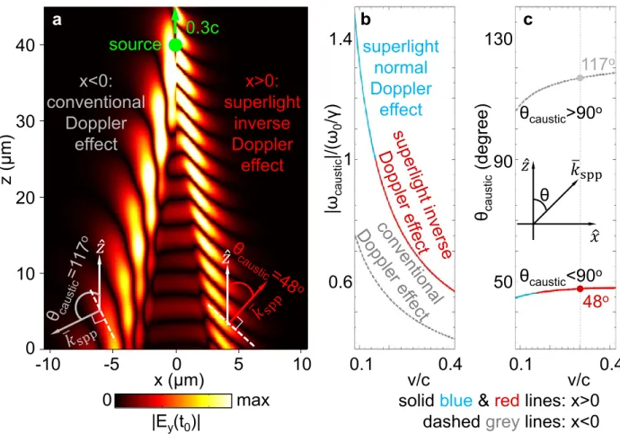
𝑥 = 𝑝𝑦 = 1 in the source static frame. Such circularly-polarized sources have been widely exploited for asymmetric excitation when 𝑣 = 0 [26]. Figure 4a shows the distribution of the emitted plasmonic field in the graphene plane in the time domain [25]; see the dynamics of the emitted plasmons in Supplementary Video. When 𝑣 = 0.3𝑐, two asymmetric caustics [27-29] are formed in the regions 𝑥 < 0 (the left side of the source) and 𝑥 > 0 (the right side of the source), respectively. Since the caustic frequency is close to the frequency of the wave component that dominates the plasmonic emission at each caustic [27, 28], it can be used to determine the type of Doppler effect that dominates each region. Due to the asymmetry of the two caustics in Fig. 4a, regions 𝑥 < 0 and 𝑥 > 0 have different caustic frequencies. The caustic frequency is calculated from 𝑑𝑑𝜔2𝜑2 = 0 [25, 27, 28], where 𝜑 = 𝑘𝑥𝑥𝑡+ 𝑘𝑧𝑧𝑡− 𝜔 [25].
Figure 4b, c shows the two caustic frequencies 𝜔caustic and the progagation angles 𝜃caustic(the anlge between 𝑘̅spp and 𝑣̅ at each caustic frequency) for the regions 𝑥 < 0 and 𝑥 > 0 as a function of 𝑣, respectively. From Fig. 4b, c, one can see that the region 𝑥 < 0 is dominated by the conventional Doppler effect with 𝜔caustic < 𝜔0/𝛾, independent of the value of 𝑣. In contrast, the region 𝑥 > 0 is dominated by the superlight normal Doppler effect with 𝜔caustic > 𝜔0/𝛾 when 𝑣 < 0.15𝑐, and, importantly, becomes dominated by the superlight inverse Doppler
9
effect with 𝜔caustic< 𝜔0/𝛾 when 𝑣 > 0.15𝑐. It shall be emphasized that, when 𝑣 > 0.15𝑐, the excited plasmon in region 𝑥 < 0 (having the conventional Doppler effect) propagates along the backward (–𝑧̂) direction with 𝜃caustic > 90𝑜; in contrast, the excited plasmon in region 𝑥 > 0 (dominant by the superlight inverse Doppler effect) propagates along the forward (+𝑧̂) direction with 𝜃caustic < 90𝑜; see Fig. 4a and Supplementary Video for an example.
To conclude, we further develop the GF theory of superlight normal Doppler effect by predicting that even inside the Cherenkov cone, the Doppler effects of light can be divided into two categories, i.e., the superlight normal and superlight inverse Doppler effects. Most importantly, the revealed superlight inverse Doppler effect breaks the century-old tenet that the inverse Doppler frequency shift is impossible in homogeneous systems with a positive refractive index. Moreover, we have numerically demonstrated the possibility for the spatial separation of the superlight inverse Doppler effect from the other Doppler effects, thus facilitating the detection of this new phenomenon. Perhaps even more important is the vision our findings emphasize: that the analoguous phenomena of the superlight inverse Doppler effect will exist in virtually any wave system in nature, including classical wave systems such as acoustic waves and surface waves, as well as quantum wave systems such as the Dirac equation; all of which have shown the occurrence of the Doppler effect, and therefore can now also support the analoguous phenomena of the superlight inverse Doppler effect. We note that the inverse Doppler effect of acoustic waves was experimentally observed in acoustic metamaterials and phononic crystals recently [30, 31]. Therefore, in additional to the highly squeezed polaritons, the acoustic waves with a slow phase velocity may provide another promising platform for the experimental demonstration of this new revealed Doppler effect.
10
1. Gill, T. P. The Doppler Effect: An Introduction to The Theory of The Effect (Logos Press, 1965).
2. Reed, E. J. Backwards Doppler shifts. Nat. Photon. 5, 199-200 (2011).
3. Veselago, V. G. The electrodynamics of substances with simultaneously negative values of 𝜖 and 𝜇. Sov. Phys. Uspekhi 10, 509-514 (1968).
4. Stancil, D. D., Henty, B. E., Cepni, A. G. & Van’t Hof, J. P. Observation of an inverse Doppler shift from left-handed dipolar spin waves. Phys. Rev. B 74, 060404 (2006).
5. Leong, K., Lai, A. & Itoh, T. Demonstration of reverse Doppler effect using a left-handed transmission line. Microwave Opt. Technol. Lett. 48, 545 (2006).
6. Chumak, A. V., Dhagat, P., Jander, A., Serga, A. A. & Hillebrands, B. Reverse Doppler effect of magnons with negative group velocity scattered from a moving Bragg grating. Phys. Rev. B 81, 140404 (2010).
7. Chen, J. et al. Observation of the inverse Doppler effect in negative-index materials at optical frequencies. Nat. Photon. 5, 239-242 (2011).
8. Belyantsev, A. M. & Kozyrev, A. B. Reversed Doppler effect under reflection from a shock electromagnetic wave. Technical Physics 47, 1477-1480 (2002).
9. Seddon, N. & Bearpark, T. Observation of the inverse Doppler effect. Science 302, 1537-1540 (2003).
10. Reed, E. J., Soljacic, M. & Joannopoulos, J. D. Reversed Doppler Effect in Photonic Crystals. Phys. Rev. Lett. 91, 133901 (2003).
11. Reed, E. J., Soljacic, M., Ibanescu, M. & Joannopoulos, J. D. Comment on “Observation of the Inverse Doppler Effect”. Science 305, 778b (2004).
12. Luo, C. Y., Ibanescu, M., Reed, E. J., Johnson, S. G. & Joannopoulos, J. D. Doppler radiation emitted by an oscillating dipole moving inside a photonic band-gap crystal. Phys. Rev. Lett. 96, 043903 (2006).
13. Liu, W. F., Russell, P. St. J. & Dong, L. Acousto-optic superlattice modulator using a fiber Bragg grating. Opt. Lett. 22, 1515-1517 (1997).
14. Ginzburg, V. L. & Frank, I. M. Dokl. Akad. Nauk SSSR 56, 583 (1947).
15. Frank, I. M. Optics of light sources moving in refractive media. Science 131, 702-712 (1960). 16. Ginzburg, V. L. Certain theoretical aspects of radiation due to superluminal motion in a
medium. Soviet Physics Uspekhi 2, 874-893 (1960).
17. Ginzburg, V. L. Radiation by uniformly moving sources (Vavilov-Cherenkov effect, transition radiation, and other phenomena). Physics-Uspekhi 39, 973-982 (1996).
18. Einat, M. & Jerby, E. Normal and anomalous Doppler effects in a dielectric-loaded stripline cyclotron-resonance maser oscillator. Phys. Rev. E 56, 5996-6001 (1997).
19. Lin, X. et al. Splashing transients of 2D plasmons launched by swift electrons. Science Advances 3, e1601192 (2017).
20. Kong, J. A. Electromagnetic Wave Theory (EMW Publishing Cambridge Massachusetts USA, 2008).
21. Pendry, J. B. Time reversal and negative refraction. Science 322, 71-73 (2008).
22. Basov, D. N., Fogler, M. M. & García de Abajo, F. J. Polaritons in van der Waals materials. Science 354, aag1992 (2016).
23. Low, T. et al. Polaritons in layered two-dimensional materials. Nat. Mater. 16, 182-194 (2017)
11
24. Lin, X. et al. All-angle negative refraction of highly squeezed plasmon and phonon polaritons in graphene–boron nitride heterostructures. Proc. Natl. Acad. Sci. USA 114, 6717-6721 (2017).
25. See Supplementary Information.
26. Bliokh, K. Y., Rodríguez-Fortuño, F. J., Nori, F. & Zayats, A. V. Spin-orbit interactions of light. Nat. Photon. 9, 796-808 (2015).
27. Shi, X. et al. Caustic graphene plasmons with Kelvin angle. Phys. Rev. B 92, 081404(R) (2015).
28. Lighthill, J. Waves in Fluids (Cambridge University Press, New York, 2001).
29. García de Abajo, F. J. & Echenique, P. M. Wake potential in the vicinity of a surface. Phys. Rev. B 46, 2663 (1992).
30. Hu, X. H., Hang, Z. H., Li, J. S., Zi, J. & Chan, C. T. Anomalous Doppler effects in phononic band gaps. Phys. Rev. E73, 015602 (2006).
31. Lee, S. H., Park, C. M., Seo, Y. M. & Kim, C. K. Reversed Doppler effect in double negative metamaterials. Phys. Rev. B 81, 241102(R) (2010).
Author Contributions All authors contributed extensively to the work presented in this paper. X.L., X.S. and B.Z. conceived the research. X.S. and X.L. performed the calculation. I.K., J.J., M.S, F.G., Z.Y. and B.Z. contributed insight and discussion on the results. X.L., X.S., B.Z., I.K., J.J. and M.S wrote the paper. B.Z., I.K., J.J. and M.S. supervised the project.
12
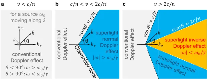
Figure 1 | K-space representation of the conventional Dopper effect, superlight normal Doppler effect and superlight inverse Doppler effect. A radiation source moves with a velocity of 𝑣̅ along the 𝑧̂ direction in a homogeneous system with a refractive index 𝑛 (𝑛 > 0). a, Only the conventional Dopper effect exists when 𝑣 < 𝑐/𝑛. b, When 𝑣 > 𝑐/𝑛, there is only the superlight normal Doppler effect inside the Cherenkov cone. c, When 𝑣 > 2𝑐/𝑛, the superlight inverse Doppler effect also appears inside the Cherenkov cone. In the source static frame, the source has a natural frequency 𝜔0. In the observer static frame, the received radiation fields have a frequency 𝜔 and a wavector 𝑘̅, where 𝜃 is the angle between 𝑘̅ and 𝑘𝑧 axis (or 𝑣̅). 𝛾 is the Lorentz factor. The Cherenkov cone is determined by the condition of 𝑣𝑐𝑜𝑠𝜃 = 𝑐/𝑛.
superlight normal Doppler effect conventio nal Do pp le r ef fect 𝑐/𝑛 < 𝑣 < 2𝑐/𝑛 b conventional Doppler effect 𝑣 < 𝑐/𝑛 for a source 𝜔0 moving along 𝑧̂ a |𝜔| > 𝜔0/𝛾 𝜃 < 90𝑜 𝜔 > 𝜔 0/𝛾 𝜃 > 90𝑜 𝜔 < 𝜔 0/𝛾 θ 𝑘̅ 𝑘𝑧 𝑘𝑥 𝑘𝑦 𝑘𝑧 𝑣 > 2𝑐/𝑛 superlight inverse Doppler effect c |𝜔| < 𝜔0/𝛾 𝑘𝑧 θ 𝑘̅ θ 𝑘̅ co nve ntio na l Do pp le r ef fect
13
Figure 2 | Real-space schematic demonstration of various Doppler effects of light. The radiation source (represented by the red dot) moves along 𝑧̂ direction in a homogeneous system with a constant positive refractive index (𝑛 > 2.5). The multiple phase-fronts, illustrated by circular lines, are equally-distributed in time. 𝜃 is the angle between 𝑘̅ and 𝑧̂ (or 𝑣̅); when 𝜃 = 0𝑜, 𝑘̅ and 𝑧̂ are in the same direction. a, When 𝑣 = 0, there is no Doppler effect. b, When 𝑣 < 𝑐/𝑛, the conventional Doppler effect exists at 𝜃 = 0𝑜. c, When 𝑣 = 𝑐/𝑛, the value of |𝜔| goes to infinity at 𝜃 = 0𝑜. d, When 𝑐/𝑛 < 𝑣 < 2𝑐/𝑛, the superlight normal Doppler effect appears at 𝜃 = 0𝑜. When 𝑣 < 2𝑐/𝑛, the distance between successive wave fronts at 𝜃 = 0o (labelled in each
𝑣 = 0.5𝑐/𝑛
𝜃 = 0
𝑜𝜔 > 𝜔
0/𝛾
𝑣 = 2𝑐/𝑛
𝜃 = 0
𝑜𝜔 = 𝜔
0/𝛾
𝑣 = 𝑐/𝑛
𝜃 = 0
𝑜𝜔
∞
𝑣 = 0
𝜃 = 0
𝑜𝜔 = 𝜔
00.5
𝛾
𝛾
𝑣 = 2.5𝑐/𝑛
𝜃 = 0
𝑜|𝜔| < 𝜔
0/𝛾
1.5𝛾
a
b
c
d
𝑣 = 1.5𝑐/𝑛
e
f
𝜃 = 0
𝑜𝜔 > 𝜔
0/𝛾
0.5𝛾
θ
𝑘̅
𝑣̅
𝑧̂
𝑥̂
𝑦̂
source
14
panel) is reduced and the waves bunch together. This leads to |𝜔| > 𝜔0/𝛾 at 𝜃 = 0oin (b-d). e, When 𝑣 = 2𝑐/𝑛, |ω| = 𝜔0/𝛾 at 𝜃 = 0o. f, When 𝑣 > 2𝑐/𝑛, the distance between successive wave fronts at 𝜃 = 0o is enlarged and the waves spread out. This leads to the superlight inverse Doppler effect (|𝜔| < 𝜔0/𝛾) at 𝜃 = 0𝑜 in (f). The Lorentz factor 𝛾 is different in each panel.
15
Figure 3 | Superlight inverse Doppler effect of graphene plasmons. A dipole with 𝜔0/2𝜋 = 10 THz moves parallel to a graphene monolayer surrounded by air. When 𝑣 = 0.1𝑐, only the conventional and superlight normal doppler effects exist. When 𝑣 = 0.3𝑐, the superlight inverse doppler effect also occurs. The chemical potential of graphene is 0.15 eV and the relaxation time is 0.3 ps. Here, and in the figure below, the frequency dispersion of graphene plasmons is considered and the effective refractive index of graphene plasmons is 𝑛 = 19 at 10 THz. The superlight inverse Doppler effect thus appears only when 𝑣 > 2𝑐/𝑛 = 2𝑐/19.
0.6 0.2 1 1.4 1.8 150 30 60 90 120 |ω|/(ω0/γ) θ (de gre e) solid lines: 𝑣 = 0.3𝑐 dashed lines: 𝑣 = 0.1𝑐
16
Figure 4 | Real-space representation of the superlight inverse Doppler effect spatially separated from other Doppler effects. A circularly-polarized dipole source with ω0/2𝜋 = 10 THz moves along the +𝑧̂ direction and parallel to the graphene monolayer. a, Distribution of the asymmetric radiation fields on the graphene plane with 𝑣 = 0.3𝑐 at the fixed time 𝑡 = 𝑡0 (when the source is at 𝑧 = 40 μm). The excited plasmons propagate backward in the region 𝑥 < 0 (the left side of source), while they propagate forward in the region 𝑥 > 0 (the right side); see the direction of the plasmonic wavevector 𝑘̅spp in the inset. b, The two caustic frequencies |𝜔caustic| as a function of 𝑣; these two frequencies dominate the plasmon emission in the regions 𝑥 < 0 and 𝑥 > 0, respectively. c, Progagation angles 𝜃caustic, i.e., the angle between 𝑘̅spp and 𝑧̂ (see inset) at each caustic frequency. When 𝑣 = 0.3𝑐, 𝜃caustic is schematically shown in (a). The region 𝑥 > 0 is dominated by the superlight inverse Doppler effect when 𝑣 > 0.15𝑐 (see (a) for example). The
117o 48o 0.1 0.4 v/c |ωcaust ic |/( ω0 /γ ) 0.6 1 1.4 0 max |Ey(t0)| b 0 40 30 20 10 z ( μ m) 0.3c source x<0: conventional Doppler effect x>0: superlight inverse Doppler effect superlight normal Doppler effect
solid blue & red lines: x>0 dashed grey lines: x<0
θcaust ic (de gre e) 50 90 130 0.1 0.4 v/c c 𝑥̂ 𝑧̂ 𝑘̅spp θ θcaustic>90o θcaustic<90o
𝑧̂
𝑧̂
a -10 10 x (μm) 5 -5 017
graphene (surrounded by air and parallel to the 𝑥-𝑧 plane) has a chemical potential of 0.15 eV and a relaxation time of 0.3 ps; the vertical distance between graphene and the source is 1 μm.