Cell phone Operated Remote Control using DTMF
Viraj Darji
Department of Electronics and Telecommunication
Engineering
Dwarkadas J. Sanghvi College of Engineering
Mumbai, Maharashtra, India
Wallace Dalmet
Department of Electronics and Telecommunication
Engineering
Dwarkadas J. Sanghvi College of Engineering
Mumbai, Maharashtra, India
Nimish Dharamshi
Department of Electronics and Telecommunication
Engineering
Dwarkadas J. Sanghvi College of Engineering
Mumbai, Maharashtra, India
Shivani Bhattachar-Jee
Assistant Professor Department of Electronics and
Telecommunication Engineering
Dwarkadas J. Sanghvi College of Engineering
Mumbai, Maharashtra, India
ABSTRACT
To control home and office electrical appliances from anywhere we designed a cell phone based remote controller using Dual-tone Multi-Frequency (DTMF) technique. The circuit designed consist of a DTMF decoder which receives and decodes the signal from the DTMF tone generator which generates frequencies according to the number pressed on the dial pad of the cell phone and accordingly performs the required operation. Using cell phone, we were able to control home electrical appliances wirelessly and remotely which has an advantage over limited range of Bluetooth or ZigBee operated devices.
Keywords
Cell phone, Dual-tone Multi-Frequency (DTMF), DTMF decoder, Bluetooth, ZigBee
1.
INTRODUCTION
In recent years, wireless systems like Remote Control have become more popular in-home networking. Also, in automation systems, the uses of wireless technologies provide several advantages that could not be achieved with the use of a wired network only [1]. The project is designed to allow easy use of a mobile phone to control appliances in the home [2]. The receiver mobile phone will be always on auto answer mode, enabling a call from known numbers. The transmitter phone then selects specific key, and this is decoded at the DTMF receiver circuit, in a BCD code format.
This BCD code is then further provided to a decoder to produce 16 different devices control signals. These signals are further processed and are then connected to a relay switch which connects this circuit to high power devices/circuits. In this method any device can be remotely turned on or off.
The principle depends upon the ability of DTMF ICs to generate DTMF output corresponding to a number or code in the number pad and to detect the same number or code from its corresponding DTMF [3]. A DTMF generator generates two frequencies corresponding to a number pressed on the number pad which is transmitted through the communication networks, through the transmitter section which here is a mobile set.
Automation aims at reducing the workload associated with machines. It is useful as many small machineries
perform very simple tasks for which supervision of progress is not needed, hence automating the process makes it very convenient and reduces both the workload and time taken for the operation and minimizes the need of human efforts [4]. This project aims majorly at a household level, but can be extended to small industrial levels.
2.
PROPOSED METHODOLOGY
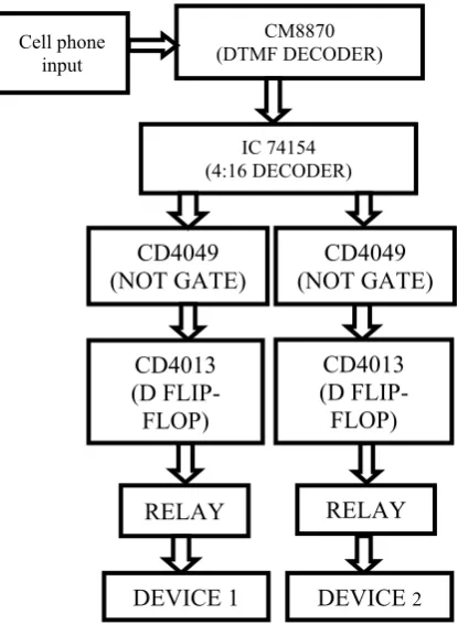
[image:1.595.334.542.399.683.2]This shows a methodology implemented for 2 devices used (total are 10 devices, all similarly connected as the shown two).
Figure 1: Block Diagram of Cellphone Operated Remote Control
IC 74154 (4:16 DECODER)
CM8870 (DTMF DECODER) Cell phone
input
RELAY
DEVICE 1
RELAY
DEVICE
2CD4049
(NOT GATE)
CD4049
(NOT GATE)
CD4013
(D
FLIP-FLOP)
2.1
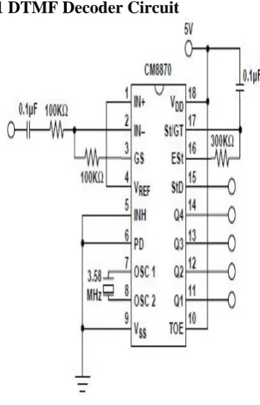
DTMF Decoder Circuit
Figure 2: DTMF Decoder Circuit
A signaling system for identifying the keys or better says the number dialed on a push button or DTMF keypad. DTMF has enabled the long distance signaling of dialing numbers in voice frequency range over telephone lines.
The DTMF (Dual Tone Multi Frequency) decoder circuit identifies the dial tone from the telephone line and decodes the key pressed on the remote telephone. Here for the detection of DTMF signaling, we are using the touch tone detector IC CM8870. It decodes the input DTMF to a 4 digital BCD code output. The CM-8870 DTMF decoder IC uses a digital counting technique to determine the frequencies of the limited tones and to verify that they correspond to standard DTMF frequencies.
The whole communication consists of the touch tone initiator and the tone decoder or detector. The DTMF tone is a form of one way communication between the dialer and the telephone exchange.
2.2
DTMF Keypad
A DTMF keypad (generator or encoder) generates a sinusoidal tone which is mixture of the column and row frequencies. The column frequencies belong to high group frequencies. The row frequencies are low group frequencies. This prevents misinterpretation of the harmonics. Also, the frequencies for DTMF are so chosen that none have a harmonic relationship with the others and that mixing the frequencies would not produce sum or product frequencies that could mimic another valid tone.
[image:2.595.90.273.74.359.2]The high-group frequencies (the column tones) are slightly louder than the low-group. The reason is for compensating for the high-frequency roll off of voice audio systems.
Figure 3: DTMF Keypad
2.3
74154 (4:16 Decoder)
These circuits in IC form are often called Demultiplexers/ Decoders and perform the opposite function to an encoder (or multiplexer). Binary data is used in digital circuits in the form of one or another binary code, which is an arrangement of the binary bits in a particular order to represent „real‟ quantities such as a set of decimal numbers (BCD code). Therefore it is often necessary in a complete digital system to convert one code to another, or to convert a binary code to drive some other device. A decoder is a combinational logic circuit that takes a binary input, usually in a coded form, and produces a one-bit output, on each of a number of output lines. The logic state (1 or 0) on any of the output lines depends on a particular code appearing on the input lines. Here 10 output lines of decoder are used to represent each pressed key, since there are only 10 keys.
2.4
CD4049 (Not Gate)
The CD4049 device is inverting hex buffers, and feature logic level conversion using only one supply voltage (VCC).
This IC is used to invert the active low outputs of decoder. This enables the output which we desire on the pressed keypad.
2.5
CD4013 (D Flip-flop)
This IC has two in build D flip-flops, and a single power supply +VCC. When the clock is high the input D propagates to the output Q as it is and when the clock is low the output is held (irrespective of the changes in input D).
Here, the output of the NOT gate is fed to the clock pin of the D flip-flop, and the input terminal D is connected to the output Q bar of the IC.
2.6
Relay
A relay is an electrically operated switch. It uses an electromagnet to mechanically operate a switch. It‟s used here to drive a separate circuit with high power requirements like a motor, which is driven by the DTMF control circuit with low power. An electromechanical relay was used in this project, as it is the more common one. The pins are connected as such:
1. The two pins connected to coil of the relay are connected between the output of the control circuit (D Flip-flop) and ground.
2. The normally open pin is kept open.
3. The normally closed pin is connected to the other circuit (e.g. motor)
4. The com pin is connected to a high voltage power supply.
When current flows through the coils, a magnetic field is generated in the rod attached to the coil, and the switch shifts from normally open to normally close, hence connecting the circuit.
This is done for all the individual outputs of the different keys pressed, enabling different high power circuits to connect to the DTMF circuit. Using a relay is optional, but using it is very efficient for power management too.
3.
IMPLEMENTATION
The implementation was divided in two parts, the DTMF decoder circuit, and the other individual components of the circuit.
The DTMF decoder circuit was connected with various values of the connecting components to vary the gain and the stability of the IC CM8870. It was debugged with various value trials. The input given to it is from a female
audio jack and an auxiliary cable via a cell phone. It was provided a supply of 6V via a voltage regulator, and a crystal oscillator with a frequency 3.57MHz.
The other half consists of individual components (Decoder, Not Gate, D flip-flop) testing and then assembling the whole circuit together and checking the output at each individual level.
3.1
Schematic Diagram
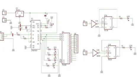
A schematic diagram consisting of a DTMF decoder circuit (IC CM8870) connected to the other elements of the project, 4x16 decoder IC (used to increase the no of controllable elements), NOT gate IC ( for the active low output of the decoder), D flip-flop IC (For the switching ON and OFF purpose of applications) on EAGLE software is shown as follows. The entire project was first simulated on Proteus to check if it were to work smoothly and whether the interfacing of ICs was correct.
There is a little modification for the short scale use of this project, in which only those applicant devices which are required to be controlled are connected to the main circuit through a jumper wire, for demonstration purposes however this procedure can be implemented for bigger models as well.
The model is shown for two individual devices, as a demonstration.
The four LEDs used at the output of the decoder circuit are connected just to check and confirm the output of the dtmf decoder circuit (need not be included).
The model is shown for only 2 outputs, expandable to 10 outputs.
[image:3.595.80.544.447.708.2]The schematic is as shown below
3.1.1
Circuit on Breadboard
Fig 5 Breadboard Implementation
3.1.2
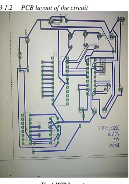
PCB layout of the circuit
Fig. 6 PCB Layout
3.2
Results and Discussions
The circuit diagram was implemented by us as per the schematic diagram shown in the breadboard and the same was implemented on a PCB later. The appropriate outputs were obtained for all sets of inputs after a few mistakes and corrections. The first part, i.e. DTMF decoder gave BCD outputs for the corresponding cellphone bindings, which is also indicated by 4 LEDs connected at the output of CM8870 IC. This is necessary to always check whether the IC is working properly and detect errors present at this stage if any. The BCD code value varies from 0001 to 1001 for 1-9 keypad numbers on phone and is 1010 for
number 0. There‟s also a yellow LED as shown in breadboard which is blinks with a very short time period whenever any number is received through the DTMF.
Now the output of the DTMF receiver is given to the 4:16 decoder IC as select inputs, which select the required device output line, note that the outputs of 74154 decoder are active low. So this output is applied to a not gate to invert the signal to active high.
This output is given to positive edge triggered D flip-flop, as a clock input, and the complement of output (Qbar) is given as input D. This is used as a switching application, as whenever the clock goes high, the output follows the input, i.e. it complements itself. As long as another clock signal, i.e. another touch on the keypad is not triggered and the power remains intact, the device can‟t toggle its state.
This is further connected to a relay circuit for every individual output of decoder, and connected directly to the device. A buzzer and a motor was connected to the output of d flip-flop and relay to check the working of the project, which was executed successfully.
4.
APPLICATIONS
DTMF have many applications ranging from industrial to agriculture to home automation. Different devices can be remotely operated by the use of DTMF [5][6].
By the use of decoder and relay circuits, home appliances can be connected to DTMF and it can be operated from anywhere.
Farmers can use this by connecting it to their irrigation channels. If he encounters some emergency and the farm is to be left uncared for, this technique could come handy. All he needs to do is to make a call from his phone and type a number.
A person can use DTMF to automate application in his home. In the high temperature of summer when he is coming back from job he can turn on ac using DTMF, so that when he reaches, his home environment would be cool.
5.
ADVANTAGES &
LIMITATIONS
Following are the advantages and a few limitations to the use of DTMF technology, some of which can be removed with further work.
5.1
Advantages of DTMF controlled
home automation system circuit:
1. One can control home appliances from anywhere.
2. It reduces wastage of electricity when we forget to switch off the lights & fans and are outside.
3. It is very low cost compared to other technologies like GSM.
[image:4.595.79.291.326.628.2]5.2
Limitations of DTMF controlled
home appliances
1. No security inbuilt. Anyone can control the appliances by calling the mobile connected to module.
2. Number of appliances is originally limited as our mobile can generate only 10 tones.
3. Does depend on network, and data carrier charges may apply.
6.
COMPARING DTMF WITH GSM
& BLUETOOTH
There are other technologies which can be used for the same purpose, namely GSM technology (GSM modules) [7]. Relatively, the DTMF is very cheaper than the GSM modules, and is ideal for household needs. Also since a cell phone is readily available anywhere these days, at very cheap rates, this circuit could be used anywhere without facing the problems of availability and damage. All that is needed is to plug in the phone whenever to be used, and plug it out when finished. Also, other technologies like Wi-Fi [8] or Bluetooth [9] can be used for the same purpose, but the key factor of DTMF is its range, which makes it a better choice when it comes to a distant control.
For accessing devices wirelessly [10] from anywhere was the main objective of this project, hence DTMF being the most suitable technology.
7.
FUTURE SCOPE
This project could be improved in many ways. It can yet be improved to meet industrial needs. The following features could be added to the project:
1. The automation could be made easier with the help of android programming. This could be done by generating a suitable interface, automatically making the calls, replacing the devices with buttons, which when clicked give the required operation. The reason to use android software is because it is supported by almost any mobile platforms these days, hence making our little dtmf module a lot more user friendly.
2. The home supported model can support till 10 devices as per the project, but if needed the model can be extended to more number of devices, by adding required number of decoders to the outputs of flip-flops. For making the working clear, let‟s take an example. Let‟s say you have connected 1st & 2nd outputs of decoder (decoder A) as inputs to another decoder, calling it decoder B. So by pressing keys 1 & keeping 2 off only on mobile, you are giving binary 10 as the input to decoder B. This enables the 3rd device attached to the corresponding output of decoder B to go high. This will make it useful at the industrial levels, and the complexity could be greatly reduced with a little android programming.
3. Security can be added by programming the app to allow only a certain number of calls to be accepted as wished by the user. This function is already available in latest smart phones, or can be added to any android phones with a minimal effort.
4. The real time monitoring can be easily made possible by adding Iot interface, which is easy to implement in the
model if used with android programming, since the values entered by the user can be recorded and reset as per the users will.
8.
CONCLUSION
The remote-control technologies are necessary in the fields like factory automation and space exploration because the human access is difficult in such places, making it a very important need in the fast paced growing tech generation. This remote-control technology can also be used to control domestic and industrial electrical devices via a cell phone communication network operated on DTMF technique. DTMF tone frequencies allow cell-phones to indicate which number is being pressed by its operator, which is decoded at the receiving end of the electrical device to perform the required operation. With the help of DTMF 10 (or extendable to many) different devices can be controlled wirelessly, remotely and with a fast response with a cell-phone. The design and implementation of Cell-phone operated remote control system is cost-effective with low power consumption and provides easy control of domestic and industrial devices.
9.
ACKNOWLEDGEMENT
Firstly, we would like to extend our sincere thanks to Ms. Shivani Bhattacharjee our guide for her guidance and constant supervision as well as for providing necessary information regarding the project. We would like to express our gratitude towards Dr. Hari Vasudevan, our Principal, for granting us the use of college library for the reference of this project, as well as our Head of Department and other faculty members and support staff for allowing us the use of college laboratories and internet facilities.
10.
REFERENCES
[1] Vaishnavi S. Gunge, Pratibha S. Yalagi, “Smart Home Automation: A Literature Review”, IJCA, RTDM 2016.
[2] E.M.C Wong, “A Phone-Based Remote Controller for Home and Office Automation,” IEEE Transactions on Consumer Electronics, vol. 40, no. 1, pp.28-34, Feb. 1994.
[3] M J. Callahan, Jr., “Integrated DTMF receiver,”ZEEE J. Solzd-State Czrcuzts, vol. Sc-14, pp. 85-90, February 1979.
[4] Rohit Sharma, Kushagra Kumar and Shashank Vig, “DTMF Based Remote Control System,” Industrial Technology, 2006. ICIT 2006. IEEE International Conference on, vol., no., pp.2380, 2383, 15-17 Dec. 2006 doi: 10.1109/ICIT.2006.372611.
[5] Zhi-Ming Lin, “A remote telephone-controlled home automation system”, IEEE Southeastcon '98, pp. 148- 152, 1998.
[6] Schneider, S., Swanson, J., Peng-Yung Woo, “Remote telephone control system”, IEEE Transactions on Consumer Electronics, vol 43, Issue 2, pp. 103 – 111, 1997.
[7] Daldal Nihat, “GSM Based Security and Control System” (In Turkish), M.Sc. Term Project, Gazi University, Ankara, 2003.
System,” World Academy of Science, Engineering and Technology, vol. 6, 2012.
[9] R. Piyare, M. Tazil, "Bluetooth based home automation system using cell phone", Consumer Electronics (ISCE) 2011 IEEE 15th International
Symposium on, pp. 192-195, 2011, ISSN 2159-1423.