DC-DC Converter Fed Closed Loop Speed Control
of BLDC Motor Drive
Rohini Doifode
Abstract: The use of photovoltaic (PV) system is increasing rapidly due to its various advantages such as, pollution free, freely available, noiseless operation etc. In this paper, PV is integrated to DC-DC converter. Brushless direct current motor (BLDC) are used due to their high efficiency. Hence, BLDC motor is used for low power household applications. As the name implies, BLDC motor do not use brushes.
They are electronically commutated. The commutation instants will be determined by hall sensor. Hall sensor will detect the position of rotor.
Three- phase voltage source inverter (VSI) is used to perform the operation of electronic commutator. The reference speed is treated as a corresponding voltage signal and is compared with the DC link voltage, whose error signal is given to a PI controller. The two converters Buck and single ended primary inductor converter(SEPIC) are compared for speed control of BLDC motor drive.. A closed loop speed control simulation of Buck and SEPIC converter have been carried out using MATLAB/ SIMULINK .
Keywords: Buck, SEPIC, PI, Hall sensor.
I. INTRODUCTION
In this paper PV cell is used as input. Renewable energy sources generate zero or less emission when compared to the non-renewable sources[1]. The energy of sun is converted to electrical energy by PV cell. A permanent magnet brushless DC motor(PMBLDCM) is widely used due to its various advantages. BLDC motors have high dynamic response, high efficiency, long operating life, higher speed range, noiseless operation[2]. Hence, this motor is suitable for low power household applications. The BLDC motor not only used in household application but also these are suitable for other application such as computer disc drives, automobile starter, automobile wipers, medical equipment and many other industrial tools[3]. In this paper, PV cell is combined to DC-DC converter which feds the BLDC motor.
A. Problem Definition
To achieve the desired value of DC voltage supply linear regulated supply is commonly used. The disadvantages of a linear regulated supply are that the output voltage is invariably less than the main output supply. A great amount of power loss takes place with these arrangement and efficiency gets reduced. Using DC-DC converter this problem can be solved and also efficiency is increased.
B. Motivation
Over past 10 years, BLDC motors replaced other motors in applications ranging from air conditioners to remote controlled drives. So it becomes essential to design and develop new strategies for speed control of BLDC motor. PV power generation is evolving as one of the most prominent renewable energy sources because of its merits such as eco-friendly nature, no noise and less maintenance.
C. Objectives of Paper
1) To study BLDC motor.
2) To design and implement the system which provides the smooth speed control.
3) To simulate a closed loop speed control model in MATLAB for Buck and SEPIC converter to observe result.
II. DC-DC CONVERTER
The DC-DC converters are widely used in regulated switch- mode DC power supplies and in motor drive applications. The main function of DC-DC converter is to convert DC input voltage into a DC output voltage and to regulate the DC output voltage with line variation. The different types of DC-DC converter are Buck, SEPIC, Buck-Boost, Cuk, Boost etc. Each DC-DC converters has own operating strategies[4,5]. In this paper, Buck and SEPIC converters are discussed.
A. Buck Converter
[image:2.612.175.428.236.316.2]Buck converter it is used for step down the voltage. It gives output voltage less than input voltage. Figure 1.1 shows the basic circuit diagram of Buck converter. It contains diode (D), filter inductor (L), filter capacitor (C), voltage source (Vs) and load resistance (R). The state of the converter in which the inductor current is never zero for any period of the time is called the continuous conduction mode (CCM)[6]. In this state, diode(D) is reverse- biased when switch is ON. In discontinuous conduction mode (DCM) inductor current is zero.
Figure 1.1 Circuit diagram of Buck converter
B. SEPIC converter
[image:2.612.119.502.430.526.2]In Buck/Boost converter topology the output voltage is inverted when compared to the voltage supplied by the battery. This voltage inversion can add complexity to a design, particularly when supplying analog components. SEPIC is a type of DC-DC converter allowing the output to be greater than or less than the input voltage[7]. Figure 1.2 shows the circuit diagram of SEPIC converter. The advantage of SEPIC converter is that its output voltage has same polarity that of input. SEPIC is useful in applications in which a battery voltage can be above and below that of the regulator's intended output.
Figure 1.2 Circuit diagram of SEPIC converter.
III. PROPOSED SYSTEM DESCRIPTION (SEPIC FED BLDC MOTOR DRIVE)
Figure 1.3 shows the block diagram of proposed system. The system contains PV, SEPIC converter, BLDC converter, BLDC motor, hall signal. The solar energy is used as source. The energy from sun is converted into electrical energy by solar cell. The input voltage obtained varies since the solar depends on atmospheric condition. The commutation instants will be determined by the rotor position and the position of the rotor is determined either by position sensors like Hall sensor, position encoder and resolver etc or by any of the sensorless techniques[8].
[image:2.612.100.499.638.710.2]Hall signal
The output of PV cell voltage is fed to SEPIC converter and that is fed to the BLDC converter. The BLDC converter is commutated based on hall sensor signal information . The output voltages of DC-DC converters are generally controlled by using a switching concept. Converters based on IGBTs and MOSFETs switches are generally used[9]. The DC power supplies and the DC quantities are not fixed, the inverter should compensate for such variations. Hall sensor senses the rotor position of BLDC motor and gives signal to controller, that controller will give PWM signals to certain switches of VSI . Electronic commutation is a process of decoding the hall Effect signals generated by the inbuilt encoder of the motor according the position of rotor. A voltage source inverter can run the BLDC motor by applying three phase square wave voltages to the stator winding of the motor. VSI has six switches for the positive pulse upper switches operates and for negative pulse lower switches operates. The stator winding of BLDC motor is typically trapezoidally wound in order to generate the trapezoidal shape back-EMF waveform[10]. Maximum torque is reached when the field lines are perpendicular. The reference speed is given as per the requirement of application. The reference speed and actual speed is compared . And the error is modified by PI controller.
IV. SIMULATION AND RESULT
A. Simulation of Buck converter fed BLDC motor
Figure shows the configurations of Buck converter fed BLDC motor for speed control. The Buck converter is designed for a 1000rpm.
[image:3.612.63.552.301.492.2]Figure 1.4. Simulation of closed loop speed control Buck converter fed BLDC Motor
Figure 1.5 to figure 1.8 shows stator current, torque, back EMF, speed waveforms for Buck fed BLDC motor for 1000 RPM
[image:3.612.87.525.552.717.2]Figure 1.6 Back EMF waveforms of Buck Converter fed BLDC Motor Drive
Figure 1.7 Torque waveform of Buck fed BLDC Motor
[image:4.612.85.530.548.715.2]B. Simulation of SEPIC Converter fed BLDC Motor
Figure 1.9 shows the proposed SEPIC converter fed BLDC drive for the speed control. PI controller is used for the speed control of the BLDC driving constant torque
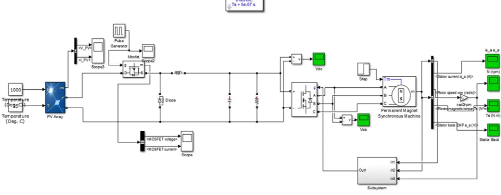
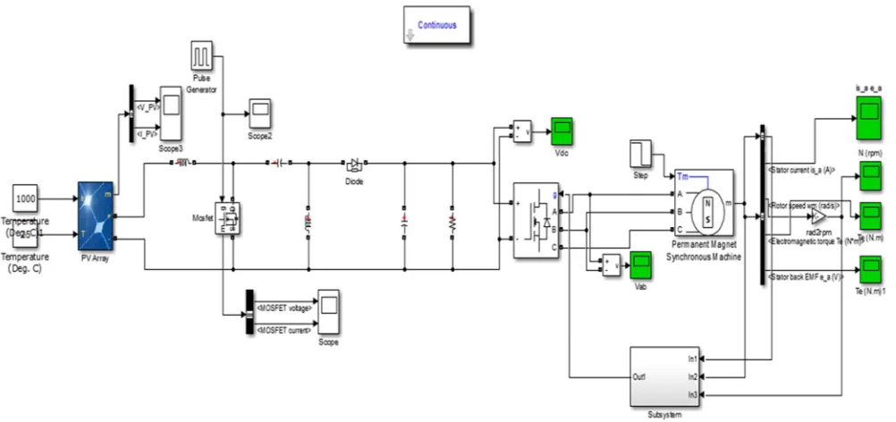
[image:5.612.78.532.453.701.2]Figure 1.9 Simulation of closed loop speed control SEPIC converter fed BLDC Motor
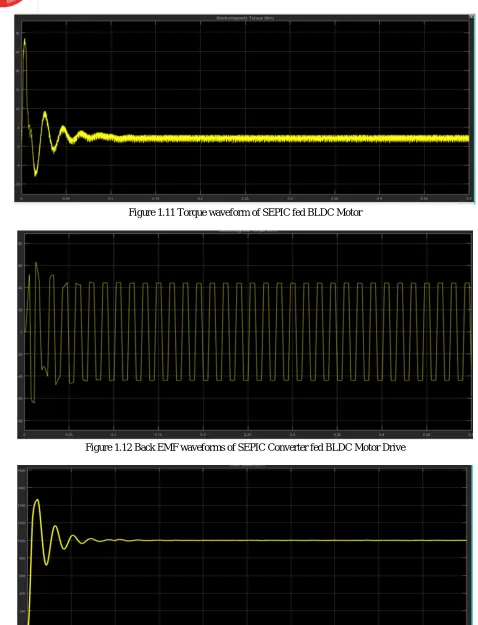
Figure 1.10 to figure 1.13 Shows stator current, torque, back EMF, speed waveforms for SEPIC fed BLDC motor waveforms for 1000 rpm.
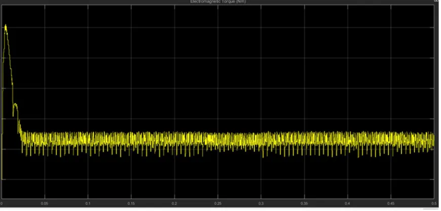
Figure 1.11 Torque waveform of SEPIC fed BLDC Motor
Figure 1.12 Back EMF waveforms of SEPIC Converter fed BLDC Motor Drive
[image:6.612.77.537.195.494.2]C. Result
1) Rise Time: Time required for the response to reach 10% to 90%ofthe final value.
2) Setting Time: Time required for the response curve to stay within the tolerance band.
While designing the controller, the time domain specifications like rise time, settling time must be minimum.
Table 4.3 Result for BUCK and SEPIC for 1000 RPM speed
Converter Rise time(sec) Settling time(sec)
Buck 0.05 0.15
SEPIC 0.01 0.04
V. CONCLUSION
The DC-DC SEPIC converter fed BLDC drive speed control for low voltage application has been proposed. The complete system has been designed and simulated in MATLAB/SIMULINK environment and implemented on a developed hardware prototype. BLDC motor is free from commutator and brushes due to this the SEPIC fed BLDC motor drive system is more simple, economical and reliable also robust and low maintenance. It is concluded using SEPIC converter and feedback control system smooth BLDC speed performance is achieved. It is concluded that the SEPIC converter fed BLDC motor drive is found to be best for low power applications when compared to Buck converter.
REFERENCES
[1] Omar Ellabban, “ Renewable and sustainable energy reviews”, Elsevier, 2014.
[2] Padmaraja Yedamale, “Hands-on Workshop: Motor Control Part 4 Brushless DC (BLDC) Motor Fundamentals,” Microchip AN885, 2003.
[3] Kirti B. Nagne, “ Comparison of DC_DC Buck Boost and SEPIC converter for control of electronically commuatated BLDC motor”, International Journal for innovative research in multidisciplinary field vol.4, Isuue-5, May2018.
[4] Bhushan R. Bawane, “A study on SEPIC converter for voltage modification fed by solar photovoltaic systems”, IEEE-International conference on computation of power, energy, information and commutation (ICCPEIC), pp: 243-247,2018
[5] Ridly on “Analysing the SEPIC Converter”, on 2006, Ridley Engineering March 2014.
[6] Muhammad H. Rashid, “Power Electronics Handbook,” the text book was published in 2001 published by Academic Press.
[7] Ms. Mona Marodkar, “Design and simulation of DC-DC converters for photovoltaic system based on MATLAB, IEEE-5 International Conference on Industrial Instrumentation and Control (ICIC) College of Engineering Pune, pp: 1478-1483, 2015.
[8] Anju Rajan P, “ Analysis of a sensor based BLDC motor with SEPIC converter for PFC and speed control”, International Journal of science, engineering and Technology Research (IJSETR), vol.4, 2015.
[9] Dr. J. Viswanatha Rao, “ SEPIC converter fed BLDC drive with closed loop speed control”, IEEE International conference on Signal Processing, Communication, Power and Embedded System (SCOPES), pp:1435-1441, 2016.