Denoising of Medical Images Using Multiwavelet
Transforms and Various Thresholding Techniques
Abdullah Al Jumah1, Mohammed Gulam Ahamad1, Syed Amjad Ali2
1Department of Computer Engineering, College of Computer Engineering & Science, Salman bin Abdulaziz University, Al-Kharj,
Saudi Arabia; 2Department of Electronics & Communication Engineering, Lords Institute of Engineering & Technology, Hyderabad,
India.
Email: [email protected]
Received August 6th, 2012; revised September 24th, 2012; accepted October 16th, 2012
ABSTRACT
The problem of estimating an image corrupted by additive white Gaussian noise has been of interest for practical rea-sons. Non-linear denoising methods based on wavelets, have become popular but Multiwavelets outperform wavelets in image denoising. Multiwavelets are wavelets with several scaling and wavelet functions, offer simultaneously Or-thogonality, Symmetry, Short support and Vanishing moments, which is not possible with ordinary (scalar) wavelets. These properties make Multiwavelets promising for image processing applications, such as image denoising. The aim of this paper is to apply various non-linear thresholding techniques such as hard, soft, universal, modified universal, fixed and multivariate thresholding in Multiwavelet transform domain such as Discrete Multiwavelet Transform, Symmetric Asymmetric (SA4), Chui Lian (CL), and Bi-Hermite (Bih52S) for different Multiwavelets at different levels, to denoise an image and determine the best one out of it. The performance of denoising algorithms and various thresholding are measured using quantitative performance measures such as, Mean Square Error (MSE), and Root Mean Square Error (RMSE), Signal-to-Noise Ratio (SNR), Peak Signal-to-Noise Ratio (PSNR). It is found that CL Multiwavelet transform in combination with modified universal thresholding has given best results
Keywords: Multiwavelets; Noise; Thresholding; Additive White Gaussian Noise; Signal-to-Noise Ratio; Discrete Multiwavelet Transforms; Chui Lian; Symmetric Asymmetric Multiwavelet Transform; Bi-Hermite Multiwavelet Transform; Modified Universal Thresholding
1. Introduction
Digital images play an important role both in daily life applications such as satellite television, Magnetic Reso-nance Imaging (MRI), computer tomography as well as in areas of research and technology such as geographical information systems and astronomy. Data sets collected by image sensors are generally contaminated by noise. Imperfect instruments, problems with the data acquisition process, and interfering natural phenomena can all de-grade the data of interest. Furthermore, noise can be in-troduced by transmission errors and compression. Thus, denoising is often a necessary and the first step to be taken before the image data is analysed. It is necessary to apply an efficient denoising technique to compensate for such data corruption. Image denoising still remains a challenge for researchers because noise removal intro-duces artifacts and causes blurring of the images. This paper describes different methodologies for noise reduc-tion giving an insight as to which algorithm should be used to find the most reliable estimate of the original
image data, given its degraded version. Noise modeling in images is greatly affected by capturing instruments, data transmission media, image quantization and discrete sources of radiation. Different algorithms are used de-pending on the noise model. Most of the natural images are assumed to have additive random noise which is modeled as a Gaussian.
The developments in wavelet theory have given rise to the wavelet thresholding method, for extracting an image from noisy data. Multiwavelets, wavelets with several scaling functions, have recently been introduced and they offer simultaneous orthogonality, symmetry and short support, which is not possible with ordinary wavelets, also called scalar wavelets. This property makes Multi-wavelets more suitable for various image processing ap-plications, especially denoising.
magnitude is less than the threshold; otherwise, it is kept or modified, depending upon the thresholding rule. The choice of threshold determines to a great extent the effi-ciency of denoising algorithm.
Denoising procedure is depicted in Figure 1.
Step 1: Original image is a medical tomographic im-age (head phantom) to which noise components like ad-ditive white Gaussian noise is added to create a noisy image.
Step 2: Pre-filtering is done on the noisy image to convert the scalar coefficients of an image into vector coefficients for Multiwavelet decomposition.
Step 3: It deals with decomposition of pre-filtered image using various Multiwavelets like GHM, CL, SA4, BiHermite52S, and their respective Multiwavelet trans-forms.
Step 4: Thresholding methods are used to remove noise from decomposed image. Here we apply Multi-wavelet thresholds such as soft, hard, universal, modified, fixed and multivariate thresholds.
Step 5: By applying inverse Multiwavelet transforms (IMWT), to thresholded coefficients, we get the denoised vector output image.
Step 6: Post filtering is done on reconstructed image to get back the denoised image coefficients in scalar form.
2. Theoretical Aspects of Multiwavelets
The idea of Multiwavelet originates from the generaliza-tion of scalar wavelets [1,2]. Instead of one scaling and one wavelet function, multiple scaling and multiple wave-let functions are used. This leads to more degree of free-dom in constructing Multiwavelets. Therefore, opposed to scalar wavelets, properties such as orthogonality, sym-metry, higher order of vanishing moments, compact sup-port can be gathered simultaneously in Multiwavelets. Multiwavelets are of mainly two types: 1) Orthogonal type such as Geronimo-Hardin-Massopust (GHM), Sym-metric AsymSym-metric (SA4), Chui-Lian (CL); and 2) Bi- Orthogonal type such as Bi-Orthogonal Hermite (Bih52S).Original medical image
Add additive white
Gaussiannoise Prefiltering
Thresholding Reconstruction
Postfiltering (denoised image)
[image:2.595.308.538.441.551.2]Decomposition
Figure 1. Block diagram of denoising using Multiwavelet transformation.
[3,4]. The scaling functions 1 and 2 are symmetric
(lin-ear phase) and they have short support (two intervals or less). The coefficients of Multiwavelets are 2 × 2 matrix. It retains the orthogonality of the Multiwavelets. The incoming signal is scalar type and is converted to vector type by using prefilter. The vector image is applied in discrete time to discrete Multiwavelet transform for low pass filtering, using low pass filter coefficients and down sampled (decimated) by 2, to get ck coefficients and high pass filter coefficients are used for high pass filtering and down sampled by two to get dk coefficients. This is the two band analysis bank. A perfect reconstruction synthe-sis bank recovers the image from the two down sampled outputs as shown in Figure 2 [5-7].
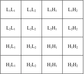
The sub-bands of a single level Multiwavelet decom-position is shown in Figure 3. It has 16 sub-bands of an image [8,9].
Multiwavelets are characterized with several scaling functions and associated wavelet functions as given in Equations (1) and (2) respectively [10-12].
t ck
2t k
(1)
k
2W t d t k
(2)where (t) is a multiscaling function, W(t) is a Multi-wavelet function.
[image:2.595.355.492.587.707.2]A multi filter has two or more low pass filters. The purpose of this multiplicity is to achieve the following properties [1].
Figure 2. A multifilter bank with low pass filter iterated once.
L1L1 L1L2 L1H1 L1H2
L2L1 L2L2 L2H1 L2H2
H1L1 H1L2 H1H1 H1H2
H2L1 H2L2 H2H1 H2H2
[image:2.595.60.288.595.704.2]Properties of
1 and
2: [13-15]1) Symmetry:1 and 2 have linear phase, i.e., they are
even functions (after a shift of the origin).
2) Short Support:ivanishes outside the interval [0, i]. Short support do not have much boundary problem. Long support must modify the function near boundaries. Wavelets have long support to achieve orthogonality. But Multiwavelets have short support and simultaneous or- thogonality.
3) Second Order Accuracy: The scaling functions
have second order accuracy, which establishes two van- ishing moments.
4) Orthogonality: The translates 1
t k
&2
t k
are all mutually orthogonal.
5) Matrix Multiscaling (Dilation) and Multiwavelet Equations: The coefficient “ck” and “dk” are 2 × 2 ma-trices multiplying vectors of scaling and wavelet func-tions as given in Equafunc-tions (3) and (4) respectively.
1
3 1
0 2 2 2 2 k k t t t c t t
k k
k k (3)
1
3 1
0 2 2 2 2 k k t t t c t t
(4)3. Thresholding Techniques
3.1. Hard Thresholding
It chooses coefficients greater than the given threshold λ
and sets others to zero. It is unsuccessful in removing large noise coefficients.
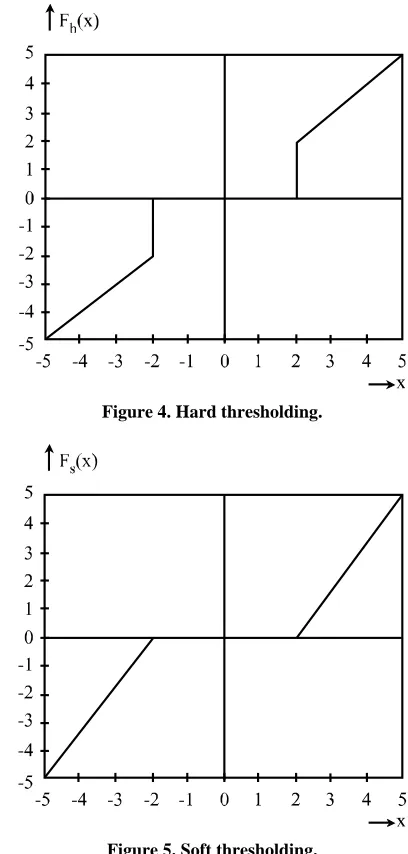
The hard thresholding, operator is defined in Equation (5) as
if0 otherwis h x x F x e
(5)
The transfer function of the same is shown in Figure 4.
If coefficient > λ, value attributes to original pixel, else its noise and we discard it.
3.2. Soft Thresholding
Soft thresholding yields smaller error than hard and is generally preferred over hard thresholding. Soft thresh- olding shrinks coefficients by the threshold λ towards zero. It is also called as shrinkage function. The soft thresholding operator is defined in Equation (6) as,
if 0 if if s x xF x x
x x (6)
The transfer function of the same is shown in Figure 5.
[image:3.595.317.521.83.510.2]Figure 4. Hard thresholding.
Figure 5. Soft thresholding.
3.3. Wavelet Thresholding [16,17]
Noise is generally present in the higher order frequency components obtained after wavelet and Multiwavelet de-composition. wavelet thresholding is the estimation tech-nique which exploits the capabilities of wavelet trans-forms. Here small coefficients dominated by noise are set to zero, when they are below a certain threshold. In this way, noise can be removed.
3.3.1. Universal Threshold
The Universal threshold was introduced by Donoho and Johnston for scalar wavelets. It is given in Equation (7) as,
universal 2 logN
, (7) where σ is the standard deviation of the noise.
Same threshold is applied to all coefficients regardless of the decomposition level.
For images, N is chosen to be the number of pixels in a row rather than the total number of pixels in the image. It is observed that this choice for N results in higher SNR values.
3.3.2. Modified Universal Threshold
1) The modified universal threshold is given in Equa-tion (8) as,
mod 2 log 2N
, (8) where σ is the standard deviation of the noise. N is the sample size.
2) Another modified universal threshold is given in Equation (9) as,
2 log 2log logN N
N
(9)where N is the sample size.
3.3.3. New Thresholding
The new threshold is given in Equation (10) as,
Newthr 2 log logN
(10)
3.3.4. Multivariate Thresholding
This method is based on parent-child relationship which exists between image pixels of various sub-bands of Mul- tiwavelet decomposition. If the parent coefficient has a small value, then the children would likely have small values. If the parent coefficient has a large value, the child might also have large values.
3.4. Measuring Parameters
3.4.1. Mean Square Error (MSE)
The MSE between the original image I(x,y) and the re-constructed imageI x y
, is given in Equation (11) as,
21 1
0 0
1
MSE My Nx I x y, I x y, MN
(11)where I(x,y) is the original image, I x y
,
is the ap-proximated version, which is actually the decompressed image and M N represents the size of an image.3.4.2. Signal-to-Noise Ratio (SNR)
It is another measure often used to compare the per-formance of reproduced images. It is given in Equation (12) as,
21 1
10 0 0
1
SNR 10log My Nx I x y( , ) MSE
MN
(12)3.4.3. Peak Signal-to-Noise Ratio (PSNR)
It is more subjective qualitative measurement of
distor-tion. For 8-bit image, it is given in Equation (13) as,
2
10
255 PSNR 10 log
MSE
(13)
3.5. Experimental Results
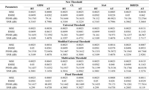
The measuring parameters such as MSE, RMSE, PSNR and SNR values for various Multiwavelet transforms with repeated row prefilter and thresholding techniques are tabulated in Table 1.
3.5.1. Using Repeated Row Pre-Filtering Method The measuring parameters such as MSE, RMSE, PSNR and SNR values for various Multiwavelet transforms with approximation prefilter and thresholding techniques are tabulated in Table 2.
3.5.2. Using Approximation Pre-Filtering Method The measuring parameters such as MSE, RMSE, and PSNR and SNR values for GHM Multiwavelet trans-forms with various thresholding techniques are tabulated in Table 3.
The measuring parameters such as MSE, RMSE, and PSNR and SNR values for GHMAP Multiwavelet trans-forms with various thresholding techniques are tabulated in Table 4.
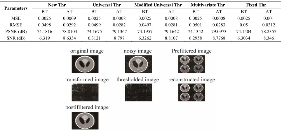
The measuring parameters such as MSE, RMSE, and PSNR and SNR values for CARDBAL2 Multiwavelet transforms with various thresholding techniques are tabu-lated in Table 5.
Denoising of tomographic image of phantom is shown in Figure 6.
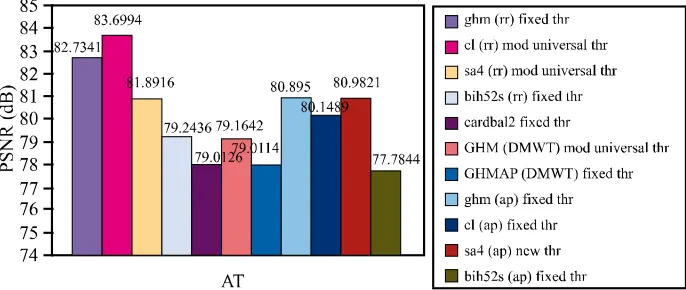
Comparison of various Multiwavelet transformation with thresholding techniques with respect to parameters such as MSE, SNR, RMSE are depicted in the Figures 7-9 respectively.
Comparison of various measuring parameters before and after thresholding is depicted in Figure 10.
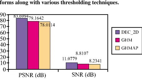
Comparison between various Multiwavelet transforms along with various thresholding techniques is given in Figure 11 and Comparison between various Multiwave-let transforms is given in Figure 12.
3.6. Conclusions
Table 1. Measurement of denoising parameters using various Multiwavelet transformation with repeated row prefilter and thresholding techniques.
New Threshold
GHM CL SA4 BiH52S Parameters
BT AT BT AT BT AT BT AT
MSE 0.0025 0.0004 0.0025 0.0011 0.0025 0.0012 0.0025 0.0155
RMSE 0.0498 0.0269 0.0498 0.0335 0.05 0.0349 0.0502 0.1246
PSNR (dB) 74.1916 82.1668 74.1866 77.6343 74.1541 77.273 74.1102 66.2236
SNR (dB) 6.324 10.3117 6.3215 8.0453 6.3052 7.8647 6.2833 2.34
Universal Threshold
MSE 0.0025 0.0007 0.0025 0.0003 0.0025 0.0008 0.0025 0.0166
RMSE 0.0499 0.0263 0.0501 0.0186 0.05 0.028 0.0499 0.1288
PSNR (dB) 74.11648 79.7172 74.1375 82.7634 74.1442 7912769 74.1866 65.9309
SNR (dB) 6.3106 9.0868 6.297 10.6101 6.3003 8.8167 6.3215 2.1936
Modified Universal Threshold
MSE 0.0025 0.0006 0.0025 0.0003 0.0025 0.0005 0.0025 0.0166
RMSE 0.0503 0.0251 0.0499 0.0167 0.0502 0.023 0.05 0.129
PSNR (dB) 74.1604 80.1536 74.1706 83.6994 74.1248 80.8961 74.1467 65.9207
SNR (dB) 6.2816 9.3049 6.3135 11.0779 6.2908 9.6747 6.3016 2.1886
Multivariate Threshold
MSE 0.0025 0.0008 0.0025 0.0004 0.0025 0.0009 0.0025 0.0166
RMSE 0.0499 0.0275 0.0498 0.0195 0.05 0.0298 0.0501 0.1289
PSNR (dB) 74.1616 79.3328 74.1816 82.2447 74.1556 78.6606 74.1863 65.9273
SNR (dB) 6.309 8.8947 6.319 10.3887 6.306 8.5585 6.297 2.1896
Fixed Threshold
MSE 0.0025 0.0003 0.0025 0.0004 0.0025 0.0019 0.0025 0.0008 RMSE 0.0503 0.0186 0.0497 0.0257 0.0498 0.0439 0.0497 0.1278
PSNR (dB) 74.1036 82.7341 74.1957 79.9169 74.1816 75.2828 74.1957 79.2436
SNR (dB) 6.28 10.5956 6.3262 9.1871 6.319 6.8696 6.3262 8.8504
Table 2. Measurement of denoising parameters using various Multiwavelet transformation with approximation prefilter and thresholding techniques.
New Threshold
GHM CL SA4 BiH52S
Parameters
BT AT BT AT BT AT BT AT
MSE 0.0025 0.0008 0.0025 0.0025 0.0025 0.0005 0.0025 0.0038
RMSE 0.0499 0.0282 0.0499 0.0499 0.0502 0.0228 0.05 0.062
PSNR (dB) 74.1765 79.14 74.1644 74.1633 74.112 80.9821 74.156 72.2764
SNR (dB) 6.3165 8.7986 6.3104 6.3224 6.3165 8.7986 6.3062 5.3664
Universal Threshold
MSE 0.0025 0.0038 0.0025 0.0023 0.0025 0.0021 0.0025 0.0131
RMSE 0.0499 0.0615 0.0499 0.0481 0.0499 0.0455 0.0501 0.1143
PSNR (dB) 74.1655 72.3592 74.203 74.4897 74.161 74.973 74.1257 66.967
SNR (dB) 6.3109 5.4078 6.3297 6.4731 6.3109 5.4078 6.2912 2.7117
Modified Universal Threshold
MSE 0.0025 0.0034 0.0025 0.0025 0.0025 0.0014 0.0025 0.0087
RMSE 0.05 0.0581 0.0499 0.0499 0.0501 0.0378 0.0498 0.0933
PSNR (dB) 74.1518 72.8456 74.1467 74.1612 74.1351 76.5872 74.1943 68.7368
SNR (dB) 6.3109 5.4078 6.3083 6.3088 6.3109 5.4078 6.3254 2.9201
Multivariate Threshold
MSE 0.0025 0.0043 0.0025 0.0023 0.0025 0.0023 0.0025 0.0135
RMSE 0.05 0.0653 0.05 0.0478 0.0502 0.048 0.0499 0.1163
PSNR (dB) 74.1437 71.8352 74.1937 74.5359 74.1199 74.5136 74.1766 66.8158
SNR (dB) 6.3001 5.1458 6.3016 6.4962 6.3001 5.1458 6.3166 2.3276
Fixed Threshold
MSE 0.0025 0.0005 0.0025 0.0006 0.0025 0.0008 0.0025 0.0011
RMSE 0.0501 0.023 0.05 0.0251 0.05 0.028 0.0502 0.0329
PSNR (dB) 74.1417 80.895 74.1442 80.1489 74.1455 79.173 74.1201 77.7814
[image:5.595.61.538.449.739.2]Table 3. Measurement of denoising parameters using direct Multiwavelet transform (GHM) using various thresholding tech- niques.
New Thr Universal Thr Modified Universal Thr Multivariate Thr Fixed Thr Parameters
BT AT BT AT BT AT BT AT BT AT
MSE 0.0025 0.0011 0.0025 0.0036 0.0025 0.0025 0.0025 0.004 0.0025 0.001
RMSE 0.0502 0.0328 0.05 0.0596 0.0502 0.0503 0.0499 0.0633 0.0499 0.0321
PSNR (dB) 74.1246 77.8223 74.1529 72.6189 74.1131 74.094 74.165 69.506 74.1541 78.0126
[image:6.595.56.539.209.278.2]SNR (dB) 6.2908 8.1397 6.3046 5.5377 6.2848 6.2752 6.3108 5.2826 6.3085 8.2347
Table 4. Measurement of denoising parameters using direct Multiwavelet transform (GHMAP) using various thresholding.
New Thr Universal Thr Modified Universal Thr Multivariate Thr Fixed Thr Parameters
BT AT BT AT BT AT BT AT BT AT
MSE 0.0025 0.0011 0.0025 0.0029 0.0025 0.0027 0.0025 0.0032 0.0025 0.001
RMSE 0.05 0.0325 0.0498 0.0538 0.05 0.0517 0.0501 0.0564 0.05 0.0321
PSNR (dB) 74.1855 77.5138 74.1406 73.4042 74.1584 73.8591 74.1346 73.1048 74.1467 78.0114
[image:6.595.51.551.314.539.2]SNR (dB) 6.3109 8.1434 6.2985 5.9305 6.3075 6.1581 6.2955 5.7807 6.3015 8.2341
Table 5. Measurement of denoising parameters using Multiwavelet transform (CARDBAL2) with identity prefilter using various thresholding.
New Thr Universal Thr Modified Universal Thr Multivariate Thr Fixed Thr Parameters
BT AT BT AT BT AT BT AT BT AT
MSE 0.0025 0.0009 0.0025 0.0008 0.0025 0.0008 0.0025 0.0008 0.0025 0.001
RMSE 0.0498 0.0292 0.0499 0.0282 0.0497 0.0281 0.0501 0.0283 0.05 0.0312
PSNR (dB) 74.1816 78.8104 74.1675 79.1367 74.1957 79.1642 74.1352 79.0973 74.1504 78.2357
SNR (dB) 6.319 8.6334 6.3121 8.797 6.3262 8.8107 6.2958 8.7768 6.3034 8.346
Figure 6. Denoising of a phantom using Multiwavelet transformation and thresholding techniques.
[image:6.595.57.540.315.539.2] [image:6.595.126.470.566.709.2]Figure 8. Comparison of various Multiwavelet transformation with thresholding techniques with respect to Signal-to-Noise Ratio.
Figure 9. Comparison of various Multiwavelet transformation with thresholding techniques with respect to Root Mean Square Error.
Figure 10. Comparison of various measuring parameters before and after thresholding.
image used in our algorithms and named it as new thresh-old.
To test the effectiveness of our algorithm, we added Gaussian noise to the 256 × 256 gray image phantom to, get noisy image and then applied Multiwavelet trans-forms and thresholding techniques to obtain denoised image. In this paper, different Multiwavelets like GHM, SA4, CL Bi-Hermite., and Multiwavelet transforms like
[image:7.595.126.469.468.613.2]Figure 11. Comparison between various Multiwavelet trans-forms along with various thresholding techniques.
Figure 12. Comparison between various Multiwavelet trans-forms.
used to evaluate the performance of algorithm.
We have compared different Multiwavelets and thresh-olding techniques used. It is found that CL is the best Multiwavelet, when used with modified universal thresh-old and repeated row prefilter.
3.7. Future Scope
Nonetheless, there is always room for improvement. Since Multiwavelets are relatively a new subject of study, only a few construction methods for Multiwavelets are avail-able. Most current filter available have two, three or fourth order of approximation. Future construction meth-ods may add even higher order of approximation, while preserving the desirable features of current methods, would most likely result in multifilters that perform even better in image denoising and compression applications. Moreover the Multiwavelet systems available presently have the multiscaling and Multiwavelet coefficients which are 2 × 2 matrices. There is a possibility that in future many more Multiwavelet systems might be developed with matrix coefficients with higher order, which could provide even better results in the field of image denois-ing.
REFERENCES
[1] G. Strang and V. Strela, “Short Wavelets and Matrix Di- lation Equations,” IEEE Transactions on Signal Process- ing, Vol. 43, No. 1, 1995, pp. 108-115.
doi:10.1109/78.365291
[2] G. Strang and V. Strela, “Orthogonal Multiwavelets with
Vanishing Moments,” Journal of Optical Engineering, Vol. 33, No. 7, 1994, pp. 2104-2107.
doi:10.1117/12.172247
[3] V. Strela, P. N. Heller, G. Strang, P. Topiwala and C. Heil, “The Application of Multiwavelet Filterbanks to Image Processing,” IEEE Transactions on Image Proc-
essing, Vol. 8, No. 4, 1999, pp. 548-563.
[4] V. Strela, and A. T. Walden, “Signal and Image Denois- ing via Wavelet Thresholding: Orthogonal and Bior- thogonal, Scalar and Multiple Wavelet Transforms,” Sta-tistic Section Technical Report TR-98-01, Department of Mathematics, Imperial College, London, 1998.
[5] B. R. Johnson, “Multiwavelet Moments and Projection Prefilters,” IEEE Transactions on Signal Processing, Vol. 48, No. 11, 2000, pp. 3100-3108.
[6] C. K. Chui and J. A. Lian, “A Study of Orthogonal Mul- tiwavelets,” Applied Numerical Mathematics, Vol. 20, No. 3, 1996, pp. 273-298. doi:10.1016/0168-9274(95)00111-5 [7] D. P. Hardin and D. W. Roach, “Multiwavelet Prefilters-I:
Orthogonal Prefilters Preserving Approximation Order P ≤ 2,” IEEE Transactions on Circuits and Systems-II: Ana-
log and Digital Signal Processing, Vol. 45, No. 8, 1998,
pp. 1106-1112.
[8] T. R. Downie and B. W. Silverman, “The Discrete Multi- ple Wavelet Transform and Thresholding Methods,” IEEE
Transactions on Signal Processing, Vol. 46, No. 9, 1998,
pp. 2558-2561.
[9] J. Y. Tham, L. X. Shen, S. L. Lee and H. H. Tan, “A Gen- eral Approach for Analysis and Application of Discrete Multiwavelet Transforms,” IEEE Transactions on Signal
Processing, Vol. 48, No. 2, 2000, pp. 457-464.
[10] K. Attakitmongcol, D. P. Hardin and D. M. Wilkes, “Mul- tiwavelet Prefilters-Part II : Optimal Orthogonal Prefil- ters,” IEEE Transactions of Image Processing, Vol. 10, No. 10, 2001, pp. 1476-1487.
[11] G. Andria, F. Attivissimo, G. Cavone, M. Spadavecchia and T. Magli, “Denoising Filter to Improve the Quality of CT Images,” Proceedings of IEEE Conference on Instru-
mentation and Measurement Technology, 5-7 May 2009,
pp. 947-950.
[12] L. X. Shen, H. H. Tan and J. Y. Tham, “Some Properties of Symmetric-Antisymmetric Orthonormal Multiwave- lets,” IEEE Transactions on Signal Processing, Vol. 48, No. 7, 2000, pp. 2161-2163.
[13] V. Strela and A. T. Walden, “Orthogonal and Biorthogo- nal Multiwavelets for Signal Denoising and Image Com- pression,” Proceedings of SPIE, Vol. 3391, 1998, pp. 96- 107. doi:10.1117/12.304924
[14] X. G. Xia, J. Geronimo, D. Hardin and B. Suter, “On Computations of Multiwavelets Transforms,” Proceed-
ings of SPIE, San Diego, July 1995.
[15] X.-G. Xia, J. Geronimo, D. Hardin and B. Suter, “Design of Prefilters for Descrete Multiwavelets Transforms,” IEEE
Transactions on Signal Processing, Vol. 44, No. 1, 1996,
pp. 25-35. doi:10.1109/78.482009
[16] E. Bala and A. Ertuzun, “A Multivariate Thresholding Te- chnique for Image Denoising Using Multiwavelets,”
[image:8.595.57.286.199.326.2]dawi Publishing Corporation, Cairo, 2005, pp. 1205-1211. [17] T.-C. Hsung, D. P.-K. Lun and K. C. Ho, “Optimizing the
Multiwavelet Shrinkage Denoising,” IEEE Transactions