Infrastructure as Code
Towards Dynamic and Programmable IT systems
Infrastructure as Code
Towards Dynamic and Programmable IT systems
A thesis submitted in fulfillment of the requirements
for the Master of Science degree
in
Internet Science and Technology
Faculty of Electrical Engineering, Mathematics and Computer Science
Author
Name: Sotirios Naziris Institute : University of Twente
7500 AE Enschede The Netherlands
Graduation Committee
Chairman: Dr. L. Ferreira Pires (UT) Members: Dr. M. J. van Sinderen (UT)
i
Abstract
The manual installation and configuration of IT systems has been a tedious and time consuming process that created several challenges to the engineers during the maintenance and management process of the IT systems. The introduction of cloud computing in combination with the rise of the virtualization technology have managed to address some of these challenges. However, these virtualized cloud systems are followed by a huge portfolio of new tools and platforms that are difficult to learn and maintain.
As a result, organizations started investigating the software-defined technology as a new and effective way to meet these new standards and serve the constantly increasing demand of the industry. The software-defined technology describes every part of an IT system that can be performed entirely by software, ranging from the infrastructure to the deployment level of an IT system.
The goal of this research project was to investigate the software-defined technology and suggest how it can be used in order to improve the static IT infrastructure of an organization. The literature study of this research focuses on the concepts and the available software-defined tools at each layer of an IT system. Based on the knowledge acquired from the literature study, a reference architecture of the infrastructure and the network layer of a generic software-defined system was proposed that describes the interconnections between the different software-defined concepts. The next step was the design of a software-defined system that uses specific tools and technologies, and is based on a specific list of requirements. The requirements were formed by studying the needs of an actual mission critical organization.
ii
Preface
This thesis was written to fulfill the final step of my “Internet Science and Technology” master programme at the University of Twente. The report had been written within a seven months period, started on May 2019 and was officially finalized on November 2019.
The project was inspired and performed in cooperation with Thales Nederland, which is a company that specializes in naval systems, logistics and air defense systems and they are in constant search of new technologies that could help them improve their current systems.
At this point, I would like to express my sincere gratitude to all the people that helped me complete this master thesis project. First of all, I would like to thank my university supervisors, Luis and Marten for their guidance throughout this research procedure. Their feedback was really useful on improving the structure of the thesis and finding the correct research approach.
Furthermore, I would like to thank my supervisors from Thales for their useful feedback and support. I would like to thank Remco for his help especially on the technical part and for our great cooperation during our weekly meetings. I would also like to thank Gerrit Binnenmars for coming up with the idea of this project and for challenging me to think creatively and unconventionally. In addition, I would like to acknowledge the help from Andreas Frank who showed great interest into my project and provided fruitful feedback on the writing of this master thesis project. Additionally, I would like to express my gratitude to the rest of the Thales employees who participated in the validation interviews and offered their valuable insights on my designs.
Moreover, I would like to thank my parents for supporting me throughout my entire life and for giving me the opportunity to continue with my studies abroad. Last but not least, I would like to thank my girlfriend Virginia for her love and emotional support during the tough times that I faced during the completion of this project.
I hope that the reading of this thesis will be useful and interesting to you, and you can always contact me in case you have any questions or comments.
Sotiris
iii
Table of contents
Abstract ... i
Preface ... ii
Table of contents ... iii
List of Figures ... vi
List of Tables ... vii
Acronyms ... viii
1 Introduction ... 1
1.1 Problem Statement ... 1
1.2 Software-Defined Concept ... 2
1.3 Scope ... 3
1.4 Research Methodology ... 4
1.5 Literature Study ... 5
1.6 Thesis Structure ... 6
2 Software-Defined Infrastructure ... 7
2.1 General Elements ... 7
2.2 Benefits of Infrastructure as Code ... 10
2.3 Provisioning Tools ... 12
2.3.1 Terraform ... 12
2.3.2 Openstack Heat ... 14
2.3.3 Comparison of the provisioning tools ... 14
2.4 Configuration Tools ... 15
2.4.1 Chef ... 15
2.4.2 Puppet ... 17
2.4.3 Ansible ... 18
2.4.4 Saltstack ... 19
2.4.5 Comparison of the configuration tools ... 20
3 Software-Defined Technology at the Network Layer ... 22
3.1 Software-Defined Networking ... 22
iv
3.1.2 Northbound Interfaces ... 25
3.1.3 SDN Controllers ... 26
4 Software-Defined Computing ... 31
4.1 Benefits of SDC ... 32
4.2 SDC Tools ... 33
5 Preparation of the design - Case Study ... 35
5.1 Requirements ... 35
5.2 Overview of the Design ... 37
5.3 Selection of Tools ... 40
5.3.1 Provisioning Tool ... 41
5.3.2 Dynamic Platform ... 41
5.3.3 Configuration Tool ... 42
5.3.4 SDN Support and Controller ... 43
6 Infrastructure Design ... 44
6.1 Provisioning ... 44
6.1.1 Creating Virtual Machines ... 44
6.1.2 Provisioning Bare Metal Machines ... 46
6.1.3 Provisioning Containers ... 48
6.2 Configuration ... 50
6.3 Architecture Realization of the Infrastructure Layer ... 50
7 Network Design ... 53
7.1 Creating virtual networks ... 53
7.2 Securing virtual networks ... 55
7.3 Connectivity with physical networks ... 57
7.3.1 VXLAN and VTEPs ... 58
7.3.2 OVSDB and Openflow support ... 58
7.3.3 L2 Gateways ... 60
7.3.4 Configuring the connections ... 61
7.4 Architecture Realization of the Network Layer ... 62
7.5 Traffic flow within the network ... 63
8 Physical Architecture of the Design ... 68
v
8.2 Possibly improved design ... 69
9 Validation ... 71
9.1 Validation approach ... 71
9.2 Results ... 72
9.2.1 Current and future proposed design of the infrastructure layer ... 73
9.2.2 Design of the network layer ... 73
9.2.3 Performance ... 74
9.2.4 Scalability and Upgradability ... 75
9.2.5 Reusability ... 75
9.2.6 Traceability ... 76
9.2.7 Learnability and Complexity ... 76
9.2.8 Costs ... 77
9.2.9 Maturity ... 78
9.3 Discussion of the results ... 78
10 Conclusions ... 81
10.1 Answers to research questions ... 81
10.2 Limitations ... 85
10.3 Contributions ... 86
10.4 Recommendations ... 87
10.5 Future work ... 88
Appendix A ... 90
Appendix B ... 92
Appendix C ... 95
Appendix D ... 96
Appendix E ... 97
Appendix F ... 99
Appendix G ... 100
Appendix H ... 101
Appendix I ... 102
Appendix J ... 103
vi
References ... 121
List of Figures
Figure 1: Overview of the DSRM ... 4Figure 2: Main elements of the software-defined infrastructure ... 9
Figure 3: Sample Terraform workflow ... 13
Figure 4: Basic structure of Chef ... 16
Figure 5: SDN vs traditional networks ... 23
Figure 6: Interfaces and SDN controllers... 27
Figure 7: The architecture of Opendaylight ... 28
Figure 8: Comparison of hypervisor (a) and container-based (b) deployments ... 31
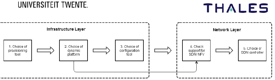
Figure 9: Design steps for the software-defined system ... 38
Figure 10: Realization of the infrastructure (a) and network (b) layer of a generic software-defined system ... 38
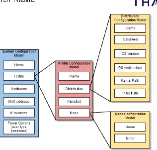
Figure 11: VM configuration model ... 45
Figure 12: Overview of the objects in Cobbler ... 46
Figure 13: Bare Metal Configuration Model... 47
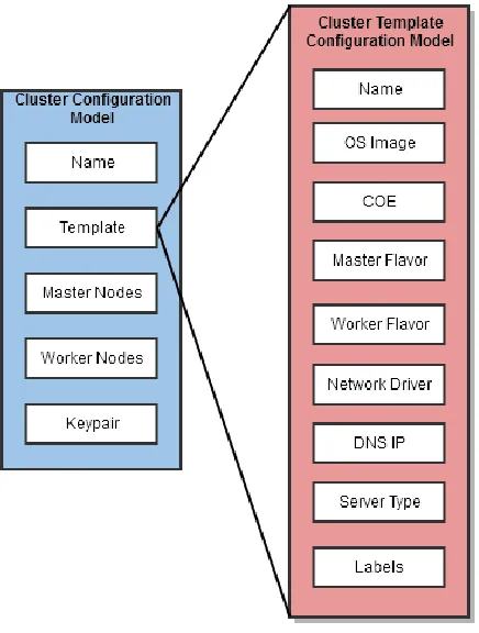
Figure 14: Container cluster configuration model... 49
Figure 15: Architecture realization of the supported infrastructure layer ... 51
Figure 16: Architecture realization of the future possibly improved infrastructure layer .. 52
Figure 17: Configuration models of the network components ... 53
Figure 18: Security group configuration model ... 55
Figure 19: FWaaS and security group protection ... 56
Figure 20: FWaaS configuration model and related concepts ... 56
Figure 21: Components of a Openflow & OVSDB physical switch ... 59
Figure 22: Components of an Open vSwitch ... 60
Figure 23: Architecture realization of the network layer ... 62
Figure 24: Traffic flows for scenario 1 ... 64
Figure 25: Traffic flow for scenario 2 ... 65
Figure 26: Traffic flows for scenario 3 ... 66
Figure 27: Traffic flows for scenario 4 ... 67
Figure 28: Physical Architecture of the current design ... 68
Figure 29: Physical architecture of the possibly improved design ... 70
vii
Figure 31: Terraform file for provisioning bare metal machines with Cobbler ... 92
Figure 32: An example of a kickstart file ... 94
Figure 33: Terraform file for provisioning container clusters of containers ... 95
Figure 34: Terraform file for creating Openstack network ... 97
Figure 35: Terraform file for creating floating IPs ... 98
Figure 36: Terraform file for creating security groups ... 99
Figure 37: Terraform file for creating firewalls ... 100
Figure 38: Transport Zone example ... 101
List of Tables
Table 1: Comparison of the provisioning tools ... 14Table 2: Comparison of the configuration tools ... 20
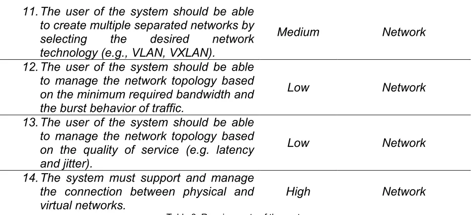
Table 3: Requirements of the system ... 37
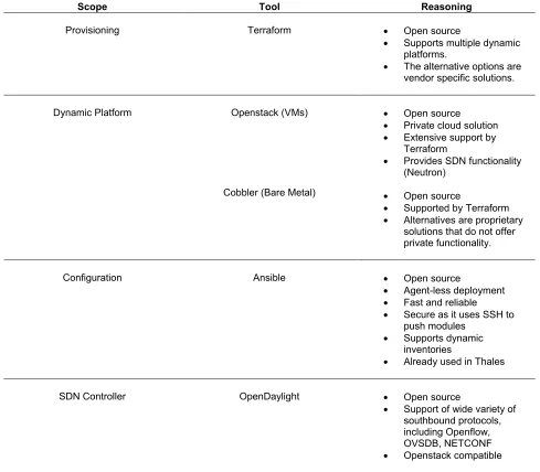
Table 4: An overview of the selected tools ... 40
Table 5: Networks of the topology ... 63
viii
Acronyms
API Application Programming Interface
AWS Amazon Web Services BNSF Base Network Service
Function
CapEx Capital Expenditures COE Container Orchestration
Engine
COTS Commercial off the Shelf CPU Central Processing Unit DDoS Distributed Denial of Service DHCP Dynamic Host Configuration
Protocol
DLUX Opendaylight User Experience DNS Domain Name System
DSL Domain Specific Language FWaaS Firewall as a Service GPU Graphical Processing Unit GUI Graphical User Interface HAL Hardware Abstraction Layer HCL Hashicorp Configuration
Language
IaaS Infrastructure as Service IaC Infrastructure as Code NaaS Networking as a Service
NFV Network Function Virtualization NIC Network Interface Card
NOS Network Operating System ODL Opendaylight
OpEx Operating Expenditures OS Operating System OVS Open vSwitch
OVSDB Open vSwitch Database PAD Programmable Abstraction of
Data
PXE Preboot Execution Environment QoS Quality of Service
SAL Service Abstraction Layer SDC Software Defined Computing SDD Software Defined Deployment SDI Software Defined Infrastructure SDN Software Defined Networking SDx Software Defined Everything TEP Tunnel Endpoint
TFTP Trivial File Transfer Protocol ToR Top of the Rack
1
1 Introduction
1.1 Problem Statement
Setting up IT infrastructures has always been a long and challenging procedure, especially in the past, in which it used to be a tedious manual process. The servers were physically installed rack by rack and the hardware components were manually configured according to the requirements of the operating systems and the running applications.
The manual installation, configuration and maintenance of the infrastructure is an expensive and time consuming process with a high chance of error. Specialized staff is required to perform the setup work (e.g., network engineers to set up the physical network, storage engineers to maintain the physical drivers, etc.) and real estate should be acquired to house all this hardware equipment. In addition, these huge data centers need maintenance, which adds up extra costs for security and operating costs, such as electricity and cooling. The servers are also prone to configuration errors and they tend to be inconsistent, as they are provisioned by many different engineers who are not in constant communication with each other and they do not share the same scope and goals. This often leads to undesired configuration abnormalities and errors, which can be crucial to the proper functionality of the entire system. Finally, in a traditional manual infrastructure, creating an isolated environment for testing and disaster recovery simulations is very costly and time consuming to be a feasible strategy, and the only way for testing and improving the system is to actually experience a disaster, which is highly risky and stressful.
2 Furthermore, cloud computing promotes the usage of scripts. Writing scripts offers some benefits compared to the manual configuration, such as the automation and standardization of a company’s IT processes. Nevertheless they are not able to entirely solve the management and configuration problem. Scripts can highly vary in the way programmers write them and that means that multiple scripts performing the same task can coexist in an organization, causing troubles to the system administrators who have to spend a lot of time and effort on each script to understand it and potentially use it. Another important issue caused by scripting is their size and their complexity. The size of a script grows as the configuration gets more complex and demanding, which results in huge script files that are almost impossible to be understood by an engineer who is new to the organization, creating a feeling of uncertainty for the operation of the system. Finally, scripts are not suitable for long term configuration because they cannot provide idempotence to the system, since scripts cannot ensure the same results if they run several times. Idempotence is a key condition for long term configuration and management of the system, and even though it can be ensured by scripts, it is very hard to implement and most of the times it is not worth the effort.
1.2 Software-Defined Concept
In the last 5 years, the industry has been trying to make the next big step towards the improvement of the configuration and the deployment of the entire IT infrastructure. Their main goal is to completely move away from any hardware dependence and create a more dynamic and responsive platform of software functionality. The term that fully describes this movement is software defined everything (SDx), which can be defined as follows:
“SDx is any physical item or function that can be performed as or automated by software” [1].
The SDx is an umbrella term that can be encountered at the following levels:
IT infrastructure level (Software-Defined Infrastructure - SDI)
Network level (Software-Defined Networking – SDN)
Computing level (Software-Defined Computing - SDC)
Application deployment level (Software-Defined Deployment - SDD)
3
1.3 Scope
This thesis answers the following main research question:
“How can the software-defined technology be used to improve a static IT infrastructure of an organization?”
This research question cannot be directly used as a basis for a academic research because it is quite general. Therefore, it is divided into the following sub-questions:
Q-1 Which are the relevant SDx technologies/ tools at each level of an IT system?
Q-2 What does the SDx technology offer at each level of an IT system?
Q-3 How to build a reference architecture for a generic software-defined system?
Q-4 How to build a software-defined system for a specific case study?
Q-5 How can a software-defined system be validated?
4
1.4 Research Methodology
The structure of this research follows the Design Science Research Methodology (DSRM) defined by Peffers [2]. The design science methodologies of Wieringa [3] and Henver [4] were also studied during the selection process; however they were not chosen, as they are not suitable for this specific research project. Wieringa’s methodology is a very thorough and strict method that provides a blueprint for performing design science research. This methodology converts the design science problems into a strict set of questions and steps that adds complexity and limitations during the research process. In contrast, the Henver’s design science framework gives more space and freedom to the researcher by proposing a cyclical process of development and evaluation. This framework is based on three design research cycles that are a combination of scientific literature and practical testing, which is not the appropriate approach for this research project.
The DSRM by Peffers is the selected approach as it provides a less strict iterative model that provides guidelines to the researcher throughout the entire research process and is based on strong literature knowledge. Figure 1 depicts an overview of the DSRM.
Figure 1: Overview of the DSRM
Based on the DSRM, the research process was divided into the following phases:
1. Problem identification and motivation: A systematic literature research was
5 2. Defining the objectives of the solution: This phase defined the objectives of the desired fully software-defined system. The objectives are translated into a list of requirements that were formed by studying the needs of a real mission critical organization.
3. Design and development: This phase includes the design of the artifact, which is a fully software-defined system. The design is based on the list of requirements from phase 2.
4. Demonstration and evaluation: The DSRM has two separate phases for the
Demonstration and the Evaluation of the artifact. In this research, these two phases are included in one phase because using the artifact for solving an actual problem is infeasible during a master thesis project due to time and practical limitations. In this phase, the proposed design is presented and validated by a group of experts by using semi-structured interviews in order to define the strong and weak points of this design and suggest possible improvements.
5. Communication: This phase communicates the importance of this research by
discussing the validation results and pointing out its contributions to the academic community and other interested organizations. This research will be published and archived into the University of Twente’s repository, and the results will be presented in a Master thesis presentation.
1.5 Literature Study
To seek answers to the previously formed research questions, it is necessary to have a better insight on the software-defined technology. The first step towards this objective, was to conduct a systematic search on the available literature. Each level of the software-defined concept (infrastructure, network, computing, deployment) was thoroughly analyzed and explained. After understanding the concepts, the components and the architecture of each software-defined level, the most popular relevant tools and technologies at each level were listed, explained and compared. The literature review was mostly performed with the use of the following academic databases:
Google Scholar
IEEE Xplore Digital Library
Scopus
ResearchGate
6 online courses explaining this technology. The learning process of writing a master thesis was also improved by studying several previous projects conducted at the University of Twente. The Google search engine was mainly used to search on websites, forums and blogs related to the software-defined technology.
1.6 Thesis Structure
7
2 Software-Defined Infrastructure
The introduction of cloud and virtualization was followed by an enormous number of new tools and platforms, which has led to a huge portfolio of systems for the IT enterprises which often requires even more time for maintenance. The industry has also evolved since then, and the demand for more flexible and easily accessible services has dramatically increased in the past few years.
This increasing demand, combined with the high need to cope with the continuously growing IT world has forced the organizations to seek for new and effective ways to meet the new high industry standards. As a result, more and more organizations made a step towards the software-defined approach. The level of the software-defined approach that refers to the IT infrastructure is called Software Defined Infrastructure (SDI) [5]. The Software Defined Infrastructure (which is mostly called Infrastructure as Code or IaC by the industry) is an attempt to address the high demand of IT services by maximizing the potential of the current IT infrastructure. A definition for IaC given by Kief Morris [6] is: “Infrastructure as Code is an approach to managing IT infrastructure for the age of the cloud, microservices and continuous delivery that is based on practices from software development “.
2.1 General Elements
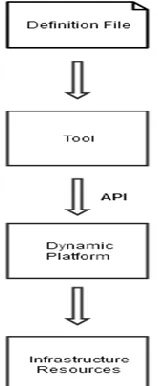
The main elements [6] of Infrastructure as Code are the definition files (also referred as code), the automation tools, the dynamic infrastructure platform and the application programming interfaces. These elements are explained with more detail below.
Definition Files
Definition files are the key element of IaC. The components of the infrastructure are defined and configured through these files. The IaC tools use these files as inputs to configure/ provision instances of the components of the infrastructure. The infrastructure components could be many things such as a server, a part of a server, a network configuration, etc.
8 files are JSON, YAML or XML, and some tools define their own domain specific language (DSL) to allow developers to describe these files.
Dynamic Infrastructure Platform
A dynamic infrastructure platform grants the bases for provisioning and managing the main infrastructure resources, such as servers, storage and network components, and ensures that they can be programmable.
There are several available dynamic infrastructure platforms. The most known examples are the public IaaS cloud services, like Azure and AWS and private IaaS, like Openstack [7]. The infrastructure can also be managed using virtualization systems such as VMware vSphere, which do not run in the cloud. Moreover, some organizations use tools as Cobbler and Foreman [8] to manage an infrastructure entirely on bare metal physical hardware.
The dynamic infrastructure platform is not affected whether it runs in the cloud, on virtual machines or bare metal, however it is essential to be programmable, on demand and self-service. Programmable refers to the previously mentioned definition files and implies that the dynamic platform should support configuration and management via these files. The term on-demand entails that the platform provides the users with the capability to create and destroy resources instantly in a matter of minutes or even seconds. Finally, a self-service platform does not only offer quick deployment of resources, but also supports the ability to change and customize resources based on the user requirements. Automation Tools
There are two different categories of automation tools for setting up the infrastructure:
provisioning tools and configuration tools. Provisioning tools are used to specify and
allocate the desired resources. These tools use the dynamic infrastructure platform to implement the allocation. Examples of these tools are Terraform, Openstack Heat and CloudFormation by Amazon. Configuration tools are used to configure and manage the already provisioned resources with the required dependencies and settings. There are plenty of available tools on this category, but the three most popular ones are Puppet, Chef and Ansible.
Application Programming Interfaces (API)
9 applications and the tools should be able to connect and exchange information with the underlying platform, and APIs is the main solution to this.
APIs are offered by the automation tools in order to provision and configure the resources of the infrastructure in the way described in the definition files. Even when using the off-the-shelf tools, the engineering teams must occasionally write their own custom scripts and extensions to program the tools against their API, so the used tools should support a wide variety of programming languages that the team is experienced with.
[image:19.612.267.346.407.600.2]REST-based APIs are the most used as they offer remote access, ease of use and high flexibility. Many tools and dynamic platforms support some programming language-specific libraries including useful classes and structures that can be used to easily deploy the components of the infrastructure and apply operations on them.
Figure 2 illustrates an overview of the elements and the interconnections between them. The idea is that the user creates the definition files that describe the infrastructure, and these files are inserted into an automation tool that via an API instructs a dynamic platform to create and manage the infrastructure resources.
10
2.2 Benefits of Infrastructure as Code
This section summarizes the benefits [6] of using IaC to deploy, manage and update the IT infrastructure in an organization.
Easily and Fast Reproduced Systems
By using IaC, the administrators (and even developers) can provision and set up an entire infrastructure from the ground up by simply writing some scripting and definition files.
Each element of the infrastructure can be repeatedly reproduced reliably and effortlessly. The IaC scripts describe all the necessary steps for creating and provisioning the requested resource, for instance which software should be installed, its correct version, hostname etc.
Writing these scripts is much easier compared to old manual way, and the development and production of the systems becomes much faster and simple. New services and new applications can be deployed on the infrastructure easily, which has led to a more efficient software development process.
Disposable Systems
IaC has improved the old static systems into dynamic, disposable systems that are able to change in a fast and easy way. The resources of the new dynamic infrastructures are easily created, destroyed, updated, resized and relocated in the system. Nevertheless, the deployed software is able to run even when the server which it runs on, is deleted, moved or resized. Improvements and patches to the infrastructure became easier as the changes can be handled smoothly. This is crucial in large scale cloud infrastructures where the system cannot rely on the underlying hardware.
Configuration Consistency
Human errors have always caused problems to the consistency of the configuration, even when standard procedures for configuration are followed. The human factor created some slight deviations in configurations that were challenging and time consuming to debug.
11 incompatibility problems are greatly reduced, and the execution of the running applications become more consistent and smooth.
Self-Documented Systems and Processes
IT teams have always been struggling to keep their documentation useful and accurate. Updates and improvements are implemented in a high pace so it is almost impossible for the documentation to be up to date with them. In addition, many people prefer to write the descriptive documents in their own way and in many cases they skip explanations as they consider them obvious or unnecessary for the reader. Therefore, most documents are not a fair representation of what really happens.
IaC has managed to solve this problem by enclosing and explaining all the necessary steps to execute a process in the definition files and the tools that actually carry out the procedure. An additional small piece of documentation is necessary in that case as well. The documents should be close (physically and meaningfully) to the code that they explain to help people acquire a good understanding of the underlying procedures.
Version Everything
Having the entire infrastructure codified in definition files opens the opportunity to use version control techniques to keep track of the committed changes, and roll back to previous stable version when an error occurs.
The Version Control System (VCS) offers a log file with all the implemented changes, the reason of the changes and the entity that made them. This feature is really useful for debugging purposes. Each feature of the system is identified by tags and version numbers, improving the tracing and fixing of more complicated abnormalities. Furthermore, the VCS supports the automatic start of a series of required actions upon the request of a new change, which is a feature of the continuous integration and continuous delivery approach.
Continuously Tested Systems and Processes
12 People are more confident to make changes if they receive fast feedback of the proposed changes. Testing is performed simultaneously with the development and that is crucial for an automated infrastructure, in which a small mistake can quickly cause significant damage.
Increased Efficiency in Software Development
IaC has boosted the productivity of the software developers. The software development cycle turned into a more efficient process, as the IT infrastructure can be deployed rapidly, easily and in several stages.
Developers can easily create their own sandbox system to launch and experiment with their code. Testing and security checking can take place in separate staging systems, and the application can be simply deployed and managed on the systems by using IaC tools. These tools can also delete the environments that are not used, freeing valuable computing power. Moreover, by shutting down all the unused resources the development environment remains clean and simple. That further increases the productivity of the engineering team, as they find a clean and friendly environment to deploy and they do not have to spend time erasing unused components from previous projects.
2.3 Provisioning Tools
Provisioning is the first step in order to build a concrete and functional infrastructure. Provisioning tools aim at setting up the foundational infrastructure components. Most of the provisioning tools are supported by an infrastructure vendor, such as Amazon or Google, but there are also tools that support multiple vendors. The most popular vendor specific provisioning tools are CloudFormation for AWS [10], Cloud Deployment Manager for the Google Cloud Platform [11] and Azure Resource Manager for Microsoft Azure Clouds [12]. The most popular open source provisioning tools are:
2.3.1 Terraform
13 Terraform describes the infrastructure through the configuration files which are written in its own developed domain-specific language called Hashicorp Configuration Language (HCL). These files are compatible to JSON and are used to deploy the requested resources. These files can be easily shared and reused to create the same environment elsewhere.
Terraform also provides execution plans, which describe the procedure that is followed in order to reach the desired state of the infrastructure. The execution plan first gives an overview of that happens by the time it is called and then Terraform actually sets up the infrastructure by executing this plan. In addition, Terraform is able to create a graph of the infrastructure resources by parallelizing the creation and modification of any non-dependent resource. The use of the execution plan combined with the produced resource graph provides more automation towards changes with less human involvement, as the user has more insight on the Terraform’s functionality, avoiding possible human errors.
Figure 3: Sample Terraform workflow [14]
14
2.3.2 Openstack Heat
Heat [15] is a product of the Openstack Foundation and is the main tool of the Openstack Orchestration program. Like the previous tools, Heat uses template files in the form of text files to deploy and set up multiple cloud resources of the desired IT infrastructure.
The infrastructure resources that can be used include: servers, volumes etc. The Openstack Telemetry [16] is also supported by Heat so that the user can include in the template file a scaling group [17] as a possible resource. In addition, the user can declare the connections and the dependencies between the resources. Heat uses these relationships in order to call the Openstack APIs that are responsible for the creation of the infrastructure, as prescribed by the user. The user can easily change the infrastructure by simply modifying the template file, and then Heat takes all the necessary steps to adjust the infrastructure to the desired state. Heat also deletes all the unused resources after application finishes its execution.
Heat supports an Openstack-native Rest API as well as a Cloud Formation-compatible Query API and the Heat template files are highly integrated with popular software configuration management tools such as Puppet and Chef. The Heat team is currently making the Heat template format compatible with the AWS Cloud Formation template format, so that many existing Cloud Formation templates can also be run on Openstack.
2.3.3 Comparison of the provisioning tools
A comparison of the described provisioning tools is illustrated in Table 1. The tools are compared based on their availability, the support of specific platforms and the used configuration language.
Metrics Terraform Openstack Heat Formation Cloud
Cloud Deployment
Manager
Azure Resource
Manager
Availability source Open source Open Closed source Closed source Closed source Supported
Platforms
Multiple
platforms Openstack AWS Google Cloud Azure Configuration
Language DSL (HCL) DSL (HOT) YAML, JSON YAML JSON
15 Terraform and Openstack Heat are open source software, whereas the rest of the tools are proprietary solutions, which are free for setting up a limited number of resources. Terraform is the only tool from the list that supports multiple dynamic platforms, enabling the combination of different resources from a variety of vendors. The other solutions are attached to a specific dynamic platform such as Openstack, AWS, Google Cloud and Azure. Terraform and Openstack Heat use domain specific languages for managing the configuration, which are YAML-based, while the rest of the tools use YAML or JSON for describing their definition files.
2.4 Configuration Tools
Once the elements of the infrastructure are provisioned, they need to be configured. Configuration management tools are used for this purpose. There are many available tools on the market, and each one of them has its own advantages and disadvantages. However, all of them serve the same goal; to configure the deployed resources according to the configuration settings. The most popular open source configuration tools based on the numbers of commits and stars in GitHub, are described in the following section.
2.4.1 Chef
Chef [18] is a configuration management tool that helps automate the IT infrastructure. Chef can manage infrastructures in the cloud, on bare metal as well as in a hybrid environment. Chef is a cl oud agnostic tool that works with many popular cloud service providers, such as Microsoft Azure, AWS, Openstack and Cloud Platform. The first version of Chef was developed in Ruby, however the latest version is partly written in Erlang and Ruby. Chef can support infrastructures up to 10.000 nodes.
The main components that form Chef are:
Chef workstation: System that is used by the user to interact with Chef. With the
16
Chef Client node: A virtual or physical machine that is managed by Chef. Chef
can also manage nodes located in the cloud. Each node has to include an agent known as chef client in order to interact with the chef server. The configuration of a node is performed through a built in tool called Ohai, which is used to describe the node attributes to the chef client.
Chef Server: A system that holds everything that is essential for configuring the
[image:26.612.147.488.279.557.2]nodes. The server stores the cookbooks, the used policies on the nodes and some metadata that describe the nodes that are managed by Chef. The Chef client which is installed on each node asks for the configuration details, such as recipes and templates from the server, and then applies the configuration to the specified node.
Figure 4: Basic structure of Chef [19]
17 can always be extended whenever there is more resources with more capabilities are needed.
Chef comes into two versions: commercial and open source. The commercial version is called Enterprise Chef and offers high availability deployment support. It is equipped with some additional features regarding security and reporting. The open source version has almost all the features of the commercial version except for the extra security and reporting. In addition, open source Chef does not support the installation of components on multiple servers.
2.4.2 Puppet
Puppet [21] is another popular configuration management tool that helps organize and configure servers. Puppet executes the configuration plans through an abstraction layer that describes the configuration elements as generic objects.
The user has to declare the resources and their attributes and that are given to Puppet as input to properly configure the resources. Puppet receives the catalog of the described resources and compares the existing state of the resources with the described one. Then it decides which actions need to be taken in order to reach an agreement between the requested state and the current state of the resources. This approach is declarative [22], since the user declares how the configuration should look like and then Puppet takes all the necessary actions to reach that intended configuration. This is the main difference with Chef, which follows a procedural approach in which the user has to describe the necessary steps to reach the desired state.
In Puppet, the resource definition files are called manifests and are written in a DSL, quite similar to Ruby. However, the user cannot simply write Ruby code in the manifests and have them executed. The manifests can be executed over and over again resulting to the same results that always match the described state.
18 between these two components is performed over a secure encrypted channel by using the SSL protocol.
2.4.3 Ansible
Ansible [23] is another powerful configuration management tool. The uniqueness of Ansible compared to other management tools is that it is also used for deployment and orchestration. Ansible is especially developed to be simple, secure, reliable and easy to learn. It offers a variety of features for an expert user but it is equally accessible to less skilled users.
Ansible does not use agents, and no additional software should be installed on the remote servers in order to manage them. Ansible manages the remote machines by using the remote management frameworks that already exists natively on the OS, for instance, SSH for Linux and UNIX machines and WinRM for Windows machines. The absence of agents results in less resource consumption on the managed machines when Ansible is not operating on them. Ansible also improves security by functioning in a push-based model where the remote machines receive only the necessary parts of the code (called modules), and the remote machines cannot interact or interfere with the configuration of the other machines. These features made Ansible suitable for high security and high performance systems.
In Ansible, the definition files to configure, automate and manage the IT infrastructure are called Playbooks. These files are written in YAML format and they describe how to perform an operation by clearly stating what should be done by each component of the infrastructure. Each Playbook consists of a list of plays that describe the automation process to a set of hosts, called the inventory. Each play includes several tasks that refer to a single host or a group of hosts in the inventory. Each task calls a module, which is a small piece of code that performs a specific job. The tasks vary from simple jobs to complex operations. Ansible can also enclose Playbook tasks into units known as roles. Ansible uses roles to apply commonly used configurations in several scenarios in a rapid and easy way.
19 JSON as input format and produce JSON as output format. In addition, Ansible can be extended to support dynamic inventory, which allows the Playbooks to be executed on a group of machines and infrastructure that are not constant and statically defined, but can run a public or private cloud provider that supports the dynamic creation and deletion of the resources. Ansible supports most of the well-known cloud providers and can always be extended to support new providers by simply writing a custom program (in any programming language) that gives a JSON inventory definition as output.
Ansible is an open source project promoted by Red Hat. The paid commercial version of Ansible is called Red Hat Ansible Tower, and offers management to complex multi-tier deployments by adding control and technical support to Ansible supported systems.
2.4.4 Saltstack
Saltstack [24] is a configuration management tool that is also used for orchestrating the infrastructure. It configures, changes and updates the IT infrastructure through a central repository. It can operate on physical, virtual and cloud servers.
Like the previous IaC tools, Saltstack aims to automate the administrative and code deployment tasks and reduce the chance of human error, by removing the manual processes as much as possible. In order to achieve that, Saltstack uses both the push and the pull method to configure the servers. It pulls configuration files and code from a central repository such as Github, and then it pushes these files to the servers remotely.
Saltstack has two main components: the Salt master and the Salt minion. The master is the central server and all minions are connected to it to get instructions. The connection between the master and the minions is encrypted based on cryptographic hashes. The minions can be commanded by the master after using public key authentication. The minions can run without a master, but the full potential of Saltstack is leveraged in a master-minions network. The user can push updates and configuration files through the master to the minions, or schedule the minions to check the master at specific time slots and pull available updates and configurations. The Saltstack’s management architecture is highly event-driven and offers self-dependence and healing to the system, as it leverages both the push and pull methods for updating and recovering from errors.
20 push commands. The Salt grains provide valuable information about the managed servers and the Salt pillars are the configuration files.
Saltstack is different from the other configuration management tools because it is fast and can operate in a multithreaded manner, so that it can perform multiple tasks simultaneously. In addition, Saltstack is developed in Python and uses it to write the configuration scripts. However, it can also render scripts developed in other languages such as YAML and JSON. That makes Saltstack a language agnostic tool that is easily accessible to a wide audience of software developers.
Saltstack is an open source framework that is operated from the Command Line Interface (CLI). The paid edition is called Saltstack Enterprise and comes with some additional features, such as a GUI support and the support for Windows, macOS and Solaris servers. The Enterprise version can also store the events in a database, offering an auditable history of the events to the user.
2.4.5 Comparison of the configuration tools
Table 2 represents a comparison between the previously mentioned configuration tools. There is a wide variety of factors, which can be used to compare this sort of tooling but for the purpose of this research the five most suitable metrics were selected.
Metrics Chef Puppet Ansible Saltstack
Configuration
Language Ruby
DSL
(Ruby-based) YAML
YAML, Python, JSON Enterprise
Version Yes Yes Yes Yes
Architecture Master-Agent Master-Agent Master only Master-Agent Configuration
Method Pull Pull Push Push and Pull
OS Support Agents (Linux & Master (Linux) Windows)
Master (Linux) Agents (Linux &
Windows)
Master (Linux) Agents (Linux &
Windows)
Master (Linux) Agents (Linux &
Windows)
Table 2: Comparison of the configuration tools
21 desired configuration. Furthermore, all tools provide an enterprise supported version, which comes with different prices depending on the size of the infrastructure.
Chef, Puppet and Saltstack follow a master-agent architecture, while Ansible requires only the installation of the master on the server machine and no additional software is installed on the client machines. Chef and Puppet follow the pull configuration method, while Ansible uses the push method. Saltstack uses both push and pull methodes to configure the servers. It pulls configuration files and code from a central repository and then it pushes these files to the servers remotely.
22
3 Software-Defined Technology at the Network Layer
Over the past decades, server virtualization has been a remarkably beneficial technology and has managed to improve the IT infrastructure significantly by providing agility, flexibility and scalability to the systems. The success of the server virtualization formed the starting point of the research on new technologies that aim to achieve such a level of virtualization of the network infrastructure.
The new technologies in this field are the Software Defined Networking (SDN) and the Network Function Virtualization (NFV). These approaches aim to contribute to a more virtualized network infrastructure that is dynamic and highly scalable. SDN and NFV are often considered as the same technology; however there are two independent technologies which are certainly related. NFV is mainly focused on deploying infrastructure services on commercial off-the-shelf hardware, while SDN is the tool that dynamically controls the network resources. NFV was developed by the telecommunication providers with the goal of reducing CapEX, OpEx and the power consumption of the service provider networks, while SDN tries to provide programmable network control and configuration. Therefore, the main area of operation of the NFV technology is service provider networks, whilst SDN mainly operates on datacenters and cloud environments. The following sub-sections give a more detailed description of the SDN technology as it is more relevant to the purpose of this research.
3.1 Software-Defined Networking
23 the Internet in its current form is a huge and important part of our society, and it is highly challenging to improve it in terms of performance and physical infrastructure. Setting up new physical network infrastructure and developing new Internet protocols requires time, money and lot of engineering effort. At the same time, the Internet applications and services have become more sophisticated with more functionalities and demands, and it is critical for the current Internet to grow in terms of scalability and performance to face these newly emerged challenges.
The idea of programmable networks has been proposed as a promising solution to tackle the problems at the current network infrastructure. Specifically, the academia introduced Software-Defined Networking (SDN) [25] as a paradigm to lift the constrains at the current network systems. The main goal of SDN is to provide agile, scalable and programmable networks. SDN separates the control plane from the underlying hardware (routers, switches) that forwards the data into the network (data plane). By detaching the control plane from the data plane, the network devices are simply responsible for forwarding data, and the control of the network is now enclosed in a logical central controller (or network operating system – NOS). Figure 5 shows the difference between a traditional network infrastructure and a SDN network in which the control plane is independent from the data plane, and it is located in the SDN controller.
Figure 5: SDN vs traditional networks [26]
The SDN architecture is composed by three main elements:
SDN Applications: Software programs that interact with the SDN controller via the
24 controller. The Southbound API defines the communication between the controller and the physical devices.
SDN Controller: It is the main component of the SDN architecture. It controls the
SDN devices via the southbound API and the SDN applications through the northbound API. The purpose of the controller is to provide a programmable and intelligent network.
SDN devices: They are the networking devices, such as routers and switches that
forward and route the data in the network, based on the flow tables described by the SDN controller via the southbound API. The devices can be real hardware switches or virtual ones. The virtual switches are implemented using Open vSwitch (OVS) [27].
3.1.1 Southbound Interfaces
OpenFlow [28] is the most popular open southbound standard for SDN. The forwarding devices known as OpenFlow switches are mainly composed by two components: flows tables and an abstraction layer. The abstraction layer allows secure communication between the switches and the SDN controller via the OpenFlow protocol. Flow tables include several flow entries, which decide where and how the flow packets should be forwarded and processed. Basically, flow entries are match-action rules that dictate what action needs to be taken when a specific match is encountered. Flow entries generally include: 1. Match fields, which are used to match incoming packets, 2. Counters, which are used to gather information and keep statistics for the particular flow such as the number of received packets, the duration of the flow etc. and 3. Set of instructions or actions that should be implemented when a match is found. Through the OpenFlow protocol, a controller can create, add, update and remove flow entries from the flow tables on the switch.
25 the packet, moving on the next flow table or forwarding the packet to the controller using the OpenFlow channel.
OVSDB [29] is another popular southbound interface. OVSDB was introduced as a part of OVS, but currently is supported by several switch platforms. The network administrators use Openflow to program the flow entries of a switch and OVSDB to configure the switch, itself. Using OVSDB, allows the engineers to create, delete and configure bridges, ports and tunnel interfaces on the switch.
Other interfaces that are suitable as a southbound standard are ForCES, POF, OpFlex, Openstate, ROFL, Hardware Abstraction Layer (HAL) and Programmable Abstraction of Data – path (PAD) [28].
3.1.2 Northbound Interfaces
Unlikely the southbound API, which is focused on the hardware, the northbound API is mostly a software-based environment. In these systems, the implementation is a central driver and the standardization mostly comes later. For the southbound interface, OpenFlow is a commonly accepted standard but there is not a widely accepted northbound API yet.
Defining an open and standard northbound interface is essential for the development and the promotion of application portability among the various control platforms. Each SDN controller has its own specific northbound API, and each of them has its own particular definitions. SFNet [30] is an example of a northbound API. It converts higher level application requirements into lower level service requests. However, the functionality of SFNet is restricted to queries that only ask the congestion state of the network, such as bandwidth reservation and multicast.
26
3.1.3 SDN Controllers
The configuration and management of most of the current networks is performed by using low-level unique commands and device-focused proprietary network operating systems, such as Cisco IOS [31] and Juniper JunOS [32]. In addition, the current network operating systems are not able to provide general functionalities for the entire network and they only provide device-specific functionalities.
SDN is a promising solution that is trying to face the current networking problems by separating the control plane from the data plane. The idea is to handle the control plane separately inside a central logical network operating system (NOS), which is known as the controller. The controller is an essential component of the SDN architecture and it is the cornerstone for configuring the network based on policies described by the network administrator. It is quite similar to the traditional operating systems and it decouples the system from the lower level device specific instructions on the forwarding devices.
[image:37.612.137.472.94.403.2]
27 Figure 6: Interfaces and SDN controllers [38]
There is a huge variety of available controllers both commercial and open source. Some examples of commercial controllers [33] are: the Cisco Application Policy Infrastructure Controller (APIC), the HP Virtual Application Networks SDN Controller, the NEC ProgrammableFlow PF6800 Controller and the VMware NSX Controller. The most used open source controllers are POX, Ryu, Trema, Floodlight and OpenDayLight. POX [34] is a controller developed in Python, and it is focused on debugging SDN errors, developing programming models and managing virtualized network resources. Ryu [35] is a component-based controller, which means that it comes with a group of pre-defined components. The network operator can create custom controller applications by modifying these pre-defined components. The components can be developed in any programming language, and the choice is up to the operator and the requirements of the applications. Trema [36] is a controller supported by NEC labs and it aims to offer an easy to code system with high performance. Ruby is used as the scripting language to increase productivity, and C is used as the compiler language to boost performance.
The Floodlight [37] controller includes a set of modules, and each of these modules
28 OpenDayLight is explained with more details in the following sub-section, as it is the current most popular SDN controller among the users’ community and the vendors, and further analysis seems necessary. Figure 6 illustrates the described SDN controllers with all the supported protocols and the connections between them.
Opendaylight
All the previously mentioned SDN controllers support only Openflow as the southbound protocol, however recent studies has showed that Openflow-based SDN architectures are inadequate for high-performance networks, and new architectures that support wide range of southbound interfaces should be invented.
[image:38.612.80.542.368.665.2]Opendaylight (ODL) [39] was introduced by the industry to solve the previously mentioned problem. ODL is developed in Java and is supported by any hardware and operating system that has Java support. In addition, it is an open source project that tries to gather a contributing community around it to improve the code and use it for the development of commercial products.
Figure 7: The architecture of Opendaylight [40]
29 southbound interfaces. The controller controls the data plane elements, but they are a separate layer outside the controller.
A. Controller platform
The main elements of the controller platform are:
The Base Network Service Functions (BNSFs): These functions gather statistics
and information about the components of the whole network, their state and their capabilities. They also offer access to the collected information to the network application via the northbound APIs. The current main built-in network services are: the topology manager, the statistics manager, the switch manager, the forwarding rules manager, the inventory manager and the host tracker.
The Platform Network Service Functions: They are plugins services that improve
the functionality of the SDN controller with specific networking tasks. Some noticeable pluggable services are the affinity metadata service, the virtual tenant network manager, the L2 switch, the service function chaining, the group-based policy and the authentication, authorization and accounting service.
The Service Abstraction Layer (SAL): It is the main element of the ODL
controller, as it enables the support of multiple southbound protocols via the southbound plugins. SAL also offers the Device Discovery service that is used by the Topology Manager to build the topology of the network and form the capabilities of the network components.
B. Southbound Interfaces
The main responsibility of the southbound protocols is to establish a communication between the SDN controller and the data plane elements. ODL uses the southbound plugins to support several southbound protocols that can manage, configure and monitor the data plane elements. Furthermore, the southbound protocols improve the compatibility of ODL with heterogeneous networks and other technologies. Some southbound protocols that are supported are OpenFlow, Open vSwitch Database (OVSDB), SNMP, BGP-LS/ PCEP and NETCONF.
C. Network Applications and Services
30 the orchestration and the redirection of the traffic based on the requirements of the network. ODL offers northbound APIs that support communication between the applications of the top layer. The northbound APIs in ODL are mainly supported by the OSGi framework and bidirectional REST APIs. Some supported network applications are:
the openDayLight User eXperience (DLUX) which is a web-based user interface.
the VTN coordinator that offers REST APIs to the users to build and manage virtual networks.
the SDNi Wrapper that offer communication between different SDN controllers.
the DDoS protection which is an application that detects and protects against DDoS attacks.
31
4 Software-Defined Computing
Software defined computing (SDC) [41] uses virtualization techniques to compute the necessary functions in the system. The virtualization technology decouples CPU and memory resources from the physical hardware, resulting to pools of resources that can be used wherever they are needed.
[image:41.612.183.437.458.663.2]The industry uses two popular technologies to achieve SDC transformation of their systems: virtual machines (VMs) and containers. A VM is defined as an isolated software framework that runs its own operating system and applications as a physical machine. A VM in order to run requires a hypervisor which is a piece of software that is placed between the hardware and the OS. The hypervisor provides the capability to the hardware to share its resources among the VMs that run on top of it. The hypervisor is also responsible for managing and monitoring the VMs. A container [42] on the other hand is a unit of software that packages up code and all its dependencies, so that the application can run quickly and reliably from one computing environment to another. Containers act as sandboxes that isolate software from the environment, and grant the functionality of the application regardless of possible differences in the deployed environments. One advantage of the containerization technology over VMs is that they do not need a fully functional OS to run, like virtual machines.
32
4.1 Benefits of SDC
SDC abstracted the data center from the physical hardware and added flexibility and automation to the system, which was a huge challenge a decade ago. Some of the most important benefits of SDC are discussed in the following section [43].
Shared Resource Pooling
One of the biggest advantages of SDC is the elasticity that it offers to the system. By adding a virtual layer between the physical hardware and the operating system, the utilization of the resources becomes easier and much more flexible. The resources are grouped into logical pools and the virtual machines/ containers can use and share the same physical resource. Upon an increase in demand, the VMs /containers can be configured to use more resources, in contrast with the bare metal servers, where the resources are limited and it is difficult and sometimes even impossible to upgrade the hardware.
Server Consolidation Anywhere
A virtual server is basically a file and as file it can be deployed everywhere in an easy manner. It can be deployed in a data center and serve almost all the traffic, on the laptop of a software developer for running tests and developing code or it can run in the cloud, where users worldwide can manage it through a browser.
Automation
The levels of automation in the new systems have dramatically increased with the introduction of SDC. The system can automatically migrate VMs and containers in case of error with no actual impact on the user experience. The system also automatically monitors the performance and the traffic load on the VMs/ containers, and takes the necessary actions to reach balance and efficiency between the hosts and the requested resources. In addition, the system can automatically start new resources in case of high demand, and shut down unused resources in periods of low demand.
Prioritizing
33 containers mitigate in case of error. Standard system cannot be served by one-sized solution for everything, and SDC can solve this by providing the necessary granularity to manage each server independently.
4.2 SDC Tools
The main elements of the SDC technology, as already mentioned, are virtualization techniques, such as VMs and the relatively new containerization technology. The main software, that creates and monitors the VMs, is the hypervisor. The hypervisor is basically a software layer that allows several VMs with different operating systems to run simultaneously at a physical machine. The hypervisor can be divided into two categories: the Type1 and the Type2 hypervisors. Type1 hypervisors, also known as bare metal hypervisors, run directly on the hardware, while the Type2 run as applications on an existing operating system on the hardware. The most used Type1 hypervisor solutions are KVM, Xen, VMWare ESXi, while the most used Type2 hypervisors are Microsoft Hyper-V and Oracle VirtualBox. The most popular tool for creating and deploying containers is Docker. Other popular tools for running containers are lxc, runc and rkt.
KVM
KVM (Kernel Based Virtual Machine) [44] is a part of Linux and was developed to run on x86 machines. KVM has a kernel module called kvm.ko that transforms the Linux kernel into a hypervisor allowing the VMs to run directly on hardware. The user can use the Virtual manager (GUI) and virsh applications (CLI) to control and manage the created VMs.
Xen
34 VMWare ESXi
VMWare is the biggest player in the hypervisor market in terms of revenue and total share. VMware offers both types of hypervisor. It offers ESXi, which is a Type1 hypervisor, and VMWare Fusion which is a Type 2 hypervisor and runs on desktops and laptops. VMWare ESXi can be downloaded for free [46]. ESXi is bare metal hypervisor that runs on a physical server directly. That increases its efficiency compared to hosted architectures and can partion hardware in an effective way to reduce costs for the customers, by increasing consolidation.
Oracle VirtualBox
VirtualBox [47] is a Type2 hypervisor that runs on Linux, Windows, Macintosh and Solaris hosts. It can run both on 32-bit and 64-bit host operating systems, which makes it highly portable. The VMs can be imported and exported in the VirtualBox by using the OVF (Open Virtualization Format). It also supports OVFs that were created by a different virtualization software.
Docker
![Figure 4: Basic structure of Chef [19]](https://thumb-us.123doks.com/thumbv2/123dok_us/9637223.466125/26.612.147.488.279.557/figure-basic-structure-of-chef.webp)
![Figure 6: Interfaces and SDN controllers [38]](https://thumb-us.123doks.com/thumbv2/123dok_us/9637223.466125/37.612.137.472.94.403/figure-interfaces-and-sdn-controllers.webp)
![Figure 7: The architecture of Opendaylight [40]](https://thumb-us.123doks.com/thumbv2/123dok_us/9637223.466125/38.612.80.542.368.665/figure-the-architecture-of-opendaylight.webp)
![Figure 8: Comparison of hypervisor (a) and container-based (b) deployments [42]](https://thumb-us.123doks.com/thumbv2/123dok_us/9637223.466125/41.612.183.437.458.663/figure-comparison-hypervisor-container-based-b-deployments.webp)