ORIGINAL RESEARCH
INTERVENTIONAL
Hemodynamics of 8 Different Configurations of Stenting for
Bifurcation Aneurysms
K. Kono and T. Terada
ABSTRACT
BACKGROUND AND PURPOSE: SACE is performed for complex aneurysms. There are several configurations of stent placement for bifurcation aneurysms. We investigated hemodynamics among 8 different configurations of stent placement, which may relate to the recanalization rate.
MATERIALS AND METHODS: We created a silicone block model of a patient-specific asymmetric bifurcation aneurysm. Enterprise closed-cell stents were deployed in the model as various configurations. 3D images of these stents were obtained by micro-CT. We performed CFD simulations for a no-stent model and 8 stent models: a single stent from a proximal vessel to a right or left distal vessel, a horizontal stent, a kissing-Y stent with a uniformly narrowed structure, a nonoverlapping-Y stent, a virtual-Y stent with no narrowed structure (fusion of 2 single stents), and 2 different crossing-Y stents with a focally narrowed structure. Hemodynamic parameters were evaluated.
RESULTS:Cycle-averaged velocity and WSS in the aneurysm were reduced because of stent placement in the following order: single stent (19% reduction in cycle-averaged velocity)⬍nonoverlapping-Y stent (29%)⬍virtual-Y stent (32%)⬍horizontal stent (39%)⬍kissing-Y stent (48%)⬍crossing-Y stent (54%). Kissing- and crossing-Y stents redirected impingement flow into the distal vessels because of lowered porosity of stents due to narrowed structures.
CONCLUSIONS: Among 8 different configurations of stent placement, kissing- and crossing-Y stents showed the strongest reduction in flow velocity in the aneurysm because of lowered porosity of stents and redirection of impingement flow. This may be a desirable reconstruction of flow hemodynamics and may decrease recanalization rates in SACE.
ABBREVIATIONS:CFD⫽computational fluid dynamics; L⫽left; PCA⫽posterior cerebral artery; R⫽right; SACE⫽stent-assisted coil embolization; WSS⫽wall shear stress
S
ACE is widely accepted for endovascular treatment of wide-neck or complex aneurysms. Several recent reports have dem-onstrated that SACE promotes occlusion of incompletely coiled aneurysms and lowers recanalization rates compared with non-stenting embolization, probably because of the hemodynamic ef-fects of stents.1-5 However, recanalization rates of SACE are8.1%–17.2%2,4,5; therefore, these rates still need to be improved.
In addition, various configurations of stentings have been pro-posed and performed for bifurcation aneurysms, including a
sin-gle stent from a proximal to a distal vessel; a waffle-cone stent6; a
horizontal stent7-9; a nonoverlapping-Y stent10; a kissing
(dou-ble-barrel) Y stent, in which both stents are deployed in a parallel fashion11,12; and a crossing-Y stent, in which the second stent is
deployed through the interstices of the first stent.12-18The
differ-ences in hemodynamics among these various configurations of stent placement are unclear, and this may be important for the recanalization rate. In crossing-Y stents, use of double closed-cell stents causes narrowing of the second stent through the interstices of the first stent,17while using an open-cell stent as the first stent
can avoid this effect of narrowing.16Whether the narrowed
struc-ture is beneficial or harmful is unknown. Using micro-CT, we obtained 3D images of various configurations of stent placement in a silicone block model of a bifurcation aneurysm. We per-formed CFD simulations to clarify differences in hemodynamics among 8 different configurations of stent placement. We also in-vestigated hemodynamics unique to the narrowed structure in the crossing-Y stent with closed-cell stents.
Received October 1, 2012; accepted after revision December 2.
From the Department of Neurosurgery, Wakayama Rosai Hospital, Wakayama, Japan.
Please address correspondence to Kenichi Kono, MD, Department of Neurosur-gery, Wakayama Rosai Hospital, 93–1 Kinomoto, Wakayama, 640-8505, Japan; e-mail: [email protected]
Indicates open access to non-subscribers at www.ajnr.org
Indicates article with supplemental on-line figures.
MATERIALS AND METHODS
Stent Geometry
A rigid silicone block model of a bifurcation aneurysm was cre-ated on the basis of an asymmetric basilar tip aneurysm with a maximum diameter of 8 mm in a patient. The diameter of the basilar artery was 2.3 mm. We have previously described detailed methods of creating patient-specific silicone models.19Briefly, on
the basis of the 3D image obtained by a rotational angiogram, a 3D real-scale model of the aneurysm was created with acrylate pho-topolymer by using a rapid prototyping system (Vision Realizer RVS-G1; Real Vision Systems, Kanagawa, Japan). The aneurysm
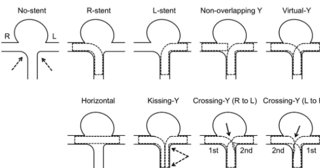
model was placed in a rectangular solid box, and the box was filled with silicone. After the silicone solidified, the acryl in-side the silicone block was removed. The aneurysm and vessels formed a cavity in the silicone model (Fig 1A). We de-ployed closed-cell stents, 28-mm Enter-prise (Cordis Neurovascular, Miami Lakes, Florida), in the silicone model in the following 7 different configurations (Fig 2): a single-stent placement from the basilar artery to the right or left PCA, a nonoverlapping-Y stent,10a
horizon-tal stent,7-9 a kissing-Y stent
(double-stent placement in a parallel fash-ion),11,12 and 2 different crossing-Y
stents with a narrowed structure.13,14,17
In 1 crossing-Y stent, crossing-Y (R to L), the first stent was deployed into the right PCA and the second stent was placed into the left PCA through the in-terstices of the first stent. The narrowed structure focally lowered the porosity of the stent (Fig 2). In another crossing-Y stent, crossing-Y (L to R), the order of stent placement was the opposite. In the kissing-Y stent, the narrowed structure of both stents was observed in the basilar artery and uniformly lowered porosity was found in both stents (Fig 2).
Stents in the silicone model were scanned by micro-CT, by using the TOSCANER-30900C3 (Toshiba IT & Control Systems, Tokyo, Japan). The resolution of the micro-CT scanner is 5
m. The images were obtained in the standard triangulated language format. The maximum-intensity-projection im-age of the crossing-Y stent revealed nar-rowing of the second stent (Fig 1B). Us-ing an engineerUs-ing design software, 3-matic (Version 6.1; Materialise n.v., Leuven, Belgium), we constructed 9 models, including the no-stent and 8 different configurations of stents (7 stents plus 1 virtual stent): no-stent, R-stent, L-R-stent, nonoverlapping-Y, virtu-al-Y, horizontal, kissing-Y, crossing-Y (R to L), and crossing-Y (L to R) (Fig 2). We created the virtual-Y stent by fusion of 2 single stents, the R-stent and L-stent. The virtual-Y stent did not have a narrowed structure. The virtual-Y stent does not exist in reality because stent struts have to interact with each other. We created this model to compare it with the crossing-Y stent with narrowing to evaluate the hemodynamic effects unique to this narrowing.
We could not obtain a clear 3D aneurysm image from the silicone model with stents by micro-CT because of an unclear boundary surface between the silicone and air. Therefore, we
FIG 1. An example of stent placement in a silicone model and an image of stents by micro-CT are shown.A, Double Enterprise stents are deployed as a crossing-Y stent in a silicone block model of the basilar tip aneurysm. The second stent shows narrowing (arrow) at the interstices of the first stent.B, A 3D image of the stents was obtained by micro-CT. A maximum-intensity-projection image shows a narrowed structure (arrow).
[image:2.594.56.375.47.211.2] [image:2.594.57.375.274.441.2]merged the image of the aneurysm obtained by rotational angiog-raphy with the image of the stents obtained by micro-CT. The stents slightly overlapped with the wall of the distal portion of the PCAs because of limitations of resolution. We trimmed the over-lapped region because we considered that the distal portion of the stent would not significantly alter hemodynamic flow around the aneurysm. We determined the neck orifice by a flat plane, which divided the aneurysm from the parental artery.
CFD Simulations
We performed CFD simulations in a similar manner as we de-scribed previously.20,21The fluid domains were extruded at the
inlet to allow fully developed flow and were meshed by using ICEM CFD software (Version 14.0, ANSYS, Canonsburg, Penn-sylvania) to create finite-volume tetrahedral elements. The small-est grid size was 0.03 mm. Small meshes were generated near the stent struts, and large meshes were generated far from the stent struts to enhance local resolution while keeping the total number of elements within reasonable bounds. The number of elements in each model ranged from approximately 1.8 million to 2.5 million, which was confirmed to be adequate to calculate the velocity and WSS by creating meshes of finer grid densities. Approximately doubled grid densities showed⬍3% differences in velocity and WSS in the aneurysm, and grid independence was confirmed. Blood was modeled as a Newtonian fluid with an attenuation of 1056 kg/m3and a viscosity of 0.0035 kg/m/s. A rigid-wall no-slip
boundary condition was implemented at the vessel walls. We performed pulsatile flow simulations with an implicit solver, CFX (Version 14.0, ANSYS), the accuracy of which had been validated previously.21For the inlet flow conditions, we used
the volumetric flow rate waveform of the basilar artery of healthy subjects given by Gwilliam et al.22The flow rate was scaled so that
cycle-averaged WSS at the parental artery would be 2.5 Pa, be-cause a WSS of 1.5–7 Pa is considered physiologic.23The mean
flow velocity at the basilar artery was approximately 0.3 m/s in all 9 models, which is within physiologic levels.24Zero pressure was
imposed at the outlets. The width of the time-step for calculation was set at 0.005 seconds. Calculations were performed for 3 car-diac cycles, and the result of the last cycle was used for analysis. We examined the following hemodynamic parameters: area-averaged velocity on the neck orifice, volume-averaged velocity in the an-eurysm, and area-averaged WSS on the dome.
RESULTS
The width of each strut of the stent obtained by micro-CT was measured. This width was a mean of 0.0752⫾0.0015 mm (n⫽
60; 95% confidence interval, 0.0713– 0.0790 mm). The accuracy of micro-CT was sufficient because the width of the strut of the Enterprise stent is 0.078 mm.25
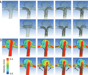
Figure 3Ashows reconstructed 3D images of vessels with 8 different configurations of stent placement. Although there were concerns about whether 2 stents could sufficiently open in the kissing-Y stent, the cross-section of the image showed good open-ing of both stents (data not shown). Figure 3Bshows the contours of flow velocity on a coronal plane at peak systole. The strongest impingement flow into the aneurysm was observed in the no-stent. The impingement flow was largely disturbed in the
horizon-tal, kissing-Y, and crossing-Y (both R to L and L to R) models. Redirection of the impingement flow into the PCAs was observed in the kissing-Y and crossing-Y models.
To quantify these redirection effects, we drew 100 streamlines at diastole from the inlet in each model. The streamlines were classified into 3 groups: those entering the aneurysm and those directly entering the right or left PCA without entering the aneu-rysm. The number of streamlines in each group was counted (Fig 4A). The R-stent or L-stent showed slight redirection effects into each side compared with the no-stent. While the horizontal stent showed few redirection effects, the kissing-Y and crossing-Y stents showed the largest flow redirection effects. Although mea-surements based on streamlines are not definitive for evaluating flow-redirection effects, they represent semiquantitative analysis. We speculate that flow-redirection effects depend on the po-rosity of stents, which varies in each stent configuration. Because it was difficult to measure the porosity of stents owing to skewed stent struts, we measured the mean pore size (area) of stents around the neck orifice responsible for redirection of the im-pingement flow (Fig 4B). In the crossing-Y stent, we measured the mean pore size of a narrowed stent (ie, the second deployed stent). We did not measure this pore size in the nonoverlapping-Y and virtual-Y stents because these models did not contain narrowed structures and the 2 stents did not interfere with each other. The horizontal stent showed the largest pore size because of swelling of stents across the neck (Fig 3A). The kissing-Y and crossing-Y stents had the smallest pore size (Fig 4B), which was caused by the narrowed structure. In the kissing-Y stent, stent pores were nar-rowed because 2 stents were deployed in parallel in the parent artery. In the crossing-Y stent, stent pores were narrowed because the second stent was deployed through the closed-cell strut of the first stent. Therefore, we demonstrated that the narrowed struc-ture results in a decrease in the pore size of stents and lowers the porosity of stents, which will redirect the impingement flow into the distal vessels.
To visualize these redirection effects, we selected 4 models: the virtual-Y, horizontal, kissing-Y, and crossing-Y (L to R) (Fig 5). Although all 4 models, except for the virtual-Y, strongly disturbed the impingement flow into the aneurysm, only the kissing-Y and crossing-Y (L to R) redirected impingement flow. The kissing-Y redirected impingement flow into both PCAs because of lowered porosity due to the uniformly narrowed structures of both stents in the basilar artery. The crossing-Y (L to R) also redirected im-pingement flow into the right PCA because of lowered porosity due to the focally narrowed structure of the second stent through the interstices of the first stent. These results clarify the unique differences between a crossing-Y stent with narrowing (cross-ing-Y) and a Y-stent without narrowing (virtual-Y). Namely, the narrowed structure produces strong hemodynamic effects by re-ducing flow velocity in aneurysms. Streamlines and contours of WSS in all 9 models are shown in On-line Figs 1 and 2.
virtual-Y (32%)⬍horizontal (39%)⬍kissing-Y (48%)⬍ cross-ing-Y (R to L) or crosscross-ing-Y (L to R) (mean, 54%). Most of the reduction in velocity or WSS was observed in the kissing-Y and crossing-Y models. The virtual-Y model showed less reduction in velocity compared with the kissing-Y and crossing-Y models, be-cause the kissing-Y and crossing-Y models redirect impingement
flow into the PCAs because of their nar-row structures, while the virtual-Y model does not have such an effect be-cause of the lack of a narrow structure. Peak systolic and diastolic hemody-namic values showed the same trends as cycle-averaged values (data not shown).
DISCUSSION
Clinical Aspects of Stents
An important issue of coil embolization of aneurysms is how to decrease recana-lization rates because recanarecana-lization may require retreatment or even cause subarachnoid hemorrhage. Several re-cent reports have demonstrated that SACE promotes occlusion of incom-pletely coiled aneurysms3-5and
signifi-cantly lowers recanalization rates com-pared with those in nonstenting coil embolization (14.9% versus 33.5%,5
8.1% versus 37.5%,4and 17.2% versus
38.9%2), probably because of the
hemo-dynamic effects of stents. Although thromboembolic complications are a concern of SACE, assessment of anti-platelet activity before treatments de-creases these complications.2,5Chalouhi
et al2recently reported that
thrombo-embolic complications occurred in 6.8% of patients in both the nonstented (n⫽147) and stented (n⫽88) groups. They also demonstrated that crossing-Y stents showed lower recanalization rates compared with those in a single stent (8.3% versus 19.2%).2 Several reports
mainly focusing on crossing-Y stents showed 0%–33.3% recanalization rates.12,13,16,26 Most interesting, only
crossing-Y stents using open-cell stents showed recanalization.
Although these previous re-ports12,13,16,26consist of a small
num-ber of case series, these results are con-sistent with our conclusions that the narrowed structure of Y-stents using closed-cell stents may decrease recanali-zation rates by reducing flow velocity in aneurysms.27With regard to concerns of
thromboembolic complications of crossing-Y stents using double closed-cell stents with a narrowed structure, as-sessment of antiplatelet activity before treatment decreases these complications to acceptable levels, as well as using nonstented coil embolization or SACE with a single stent.14In clinical practice, in
addition to the recanalization rate, properties of open- or closed-cell stents, such as ease of delivery, stability, and vessel wall appo-sition, should be considered.3
FIG 3. A, Reconstructed images of 8 different configurations of stent placement and no-stent are shown. The arrangement of panels is the same as in Fig 2. In the first row, from left to right, no-stent, R-stent, L-stent, nonoverlapping-Y, and virtual-Y models are shown. In the second row, from left to right, horizontal, kissing-Y, crossing-Y (R to L), and crossing-Y (L to R) models are shown.B,Contours of flow velocity on a coronal plane at peak systole are shown in the same arrangement as inA. The strongest jet flow into the aneurysm can be seen in no-stent. The jet flow is largely disturbed in the horizontal, kissing-Y, and crossing-Y models. Redirection of flow into the right or the left distal vessel is observed in the kissing-Y (dashed arrows) and crossing-Y (solid arrows) models.
[image:4.594.63.373.46.310.2] [image:4.594.58.372.423.571.2]Cekirge et al14showed that crossing-Y stents by using
Enter-prise stents without coils can occlude aneurysms, and they con-sidered that the Enterprise stent has stronger hemodynamic ef-fects than an open-cell stent because of its narrow interstices. Our study supports the results of Cekirge et al because we found that a crossing-Y stent with narrowing, the crossing-Y, reduced flow velocity in aneurysms more than a Y-stent without narrowing, the virtual-Y. Therefore, crossing-Y stents by using double closed-cell stents may be superior to open-cell stents for reducing the recan-alization rate.
There are 2 other configurations of Y-stent: the nonoverlap-ping-Y stent10 and the kissing-Y stent.11,12Nonoverlapping-Y
stents are the least effective in reducing the velocity in aneurysms among all configurations of Y-stents. The kissing-Y stent and crossing-Y stent reduce velocity by redirecting impingement flow (Fig 6). Although there are a few reported cases of using kissing-Y stents,11,12the kissing-Y stent may also reduce recanalization
rates and occlude aneurysms without coils as in cases of cross-ing-Y stents using Enterprise stents.14
Other than Y-stents, single-stent placement, horizontal stent placement,7-9or waffle-cone-configuration stent placement6are
alternative methods for SACE of bifurcation aneurysms. We did not include a waffle-cone-configuration stent placement in this study. However, this omission does not change our conclusions because waffle-cone-configuration stent placement will not dis-turb impingement flow and it will probably reduce flow velocity in aneurysms less than in a single-stent placement (ie, R-stent or
L-stent). Considering hemodynamic ef-fects, our study demonstrated that the kissing-Y or crossing-Y stent is prefera-ble. In clinical practice, consideration of other issues, such as the technical problems of each configuration of stent placement, selection of stents on the basis of stent properties and pro-files, and vascular geometries, should be taken into consideration.3,13,14 Hemodynamics of Stents
Hemodynamics of several configura-tions of stent placement for aneurysms has been previously studied.28-31
How-ever, most studies compared hemody-namics between nonstenting and stent-placement models, or among different designs of stents or multiple stentings of stent-in-stent configurations. They did not investigate hemodynamic differ-ences among different configurations of stent placement. While we used vascu-lar-specific conformed stent geometry obtained by micro-CT, in most of the previous studies,28,31stents were
virtu-ally conformed to fit into a parent vessel lumen and were deployed across an an-eurysm neck. Because the geometry and porosity of stents change by the vascular geometry and the radius of vessels, vir-tual deployment is not appropriate for reproducing the real ge-ometry of stents deployed in vessels. Our study shows that changes in the porosity of stents are important for hemodynamics due to stent placement. Among the 8 different configurations used in our study, kissing-Y and crossing-Y stents showed the strongest reduction in flow because of the narrowed structures, which lowered the porosity of stents and redirected flow.
A few studies have investigated the flow dynamics of Y-stents.30,31Canto´n et al30and Babiker et al31performed in vitro
flow studies of crossing-Y stents with double open-cell stents by using particle image velocimetry. They showed that the cross-ing-Y stent reduced flow velocity in an aneurysm by 11%30or
22.0%– 42.9%.31Both studies used open-cell stents, and there was
no narrowed structure in the Y-stent. Babiker et al31also
per-formed CFD simulations, but only for single-stent-placement mod-els, which correspond to the L-stent and horizontal stents in our models. In our study, because we created a silicone model and used micro-CT, we were able to obtain 3D images of various configura-tions of stent placement, including a crossing-Y stent with a nar-rowed structure, and showed that its narnar-rowed structure has a unique function of redirection of impingement flow into distal vessels.
Most CFD studies on stents for aneurysms, including this study, did not include coils in simulations because of technical difficulties. While flow-diverter stents can be used without coils, high-porosity stents, such as Enterprise stents, are generally used with coils because they usually cannot occlude aneurysms without coils. In this study, our intention was not to show that the Enterprise
[image:5.594.56.373.48.332.2]stent works as a flow diverter or to recommend stent-only therapy, but to demonstrate that the crossing-Y or kissing-Y stent with coils may reduce recanalization rates. In aneurysm treatments, we should first consider a simple strategy, such as coil embolization with no stent or a single stent. In case of complex or recanalized aneurysms, the results in this study may be helpful and the crossing-Y or kiss-ing-Y stent with coils may be considered.
Limitations of the Study
In our CFD study, we simplified several properties, such as the viscoelasticity of the vessel wall and the non-Newtonian prop-erty of the blood for technical reasons. Although the main hemodynamic features are thought to be preserved,32 these
simplifications may cause differences between the results of CFD simulation and the in vivo state. Specifically, the present CFD study has the following limitations: First, single vascular geometry was examined. Different vascular geometries may cause different CFD results. The aneurysm model is relatively symmetric, and the size of the aneurysm is not large. Some stent configurations may be unnecessary or unrealistic in this model. Second, the geometry of stents slightly changes each time with stent placement, which may lead to different hemo-dynamic results. Third, we extruded the fluid domain at the inlet to allow fully developed flow, which neglected the shape of the proximal artery. A curvature could lead to a velocity profile that is not parabolic.33Fourth, we did not include coils
in the CFD simulations because of technical difficulties, while we basically assumed SACE in this study. Fifth, the number of elements for the CFD simulations may be insufficient to calcu-late absolute hemodynamic values, though we consider that they are sufficient to show global flow patterns and compare them among the models.
Despite these 5 limitations, we consider that our
conclu-sions are still valid because a narrow structure is an important factor for re-directing flow, which is maintained in other vascular geometries or slightly different stent geometries in the same configurations. In addition, because our conclusions do not depend on the absolute values of hemodynamic pa-rameters but on comparison among the models, our conclusions are rela-tively robust. Therefore, we consider that the reduction in flow in aneu-rysms among the 8 different configu-rations of stent placement (Fig 6) would not substantially change, even if we took these 5 limitations into consideration.
CONCLUSIONS
Among 8 different configurations of stent placement for a bifurcation aneu-rysm, kissing- and crossing-Y stents show the strongest effects on flow reduc-tion because of their narrowed struc-tures, which lower the porosity of stents and redirect impingement flow into distal vessels. This may be a desirable reconstruction of flow hemodynamics and may decrease the recanalization rate in SACE. Although this study uses only single vascular geometry, these results may be applicable to other shapes of bifurcation aneurysms because narrowed structures do not depend on vascular geometry but on configurations of stent placement instead.
REFERENCES
1. Wakhloo AK, Linfante I, Silva CF, et al.Closed-cell stent for coil embolization of intracranial aneurysms: clinical and angiographic results.AJNR Am J Neuroradiol2012;33:1651–56
2. Chalouhi N, Jabbour P, Gonzalez LF, et al.Safety and efficacy of endovascular treatment of basilar tip aneurysms by coiling with and without stent-assistance: a review of 235 cases.Neurosurgery
2012;71:785–94
3. Izar B, Rai A, Raghuram K, et al.Comparison of devices used for stent-assisted coiling of intracranial aneurysms. PLoS One
2011;6:e24875
4. Lawson MF, Newman WC, Chi YY, et al.Stent-associated flow re-modeling causes further occlusion of incompletely coiled aneu-rysms.Neurosurgery2011;69:598 – 603
5. Piotin M, Blanc R, Spelle L, et al.Stent-assisted coiling of intracra-nial aneurysms: clinical and angiographic results in 216 consecu-tive aneurysms.Stroke2010;41:110 –15
6. Horowitz M, Levy E, Sauvageau E, et al.Intra/extra-aneurysmal stent placement for management of complex and wide-necked-bi-furcation aneurysms: eight cases using the waffle cone technique.
Neurosurgery2006;58(4 suppl 2):ONS-258 – 62, discussion ONS-262 7. Wanke I, Gizewski E, Forsting M.Horizontal stent placement plus coiling in a broad-based basilar-tip aneurysm: an alternative to the Y-stent technique.Neuroradiology2006;48:817–20
8. Siddiqui MA, J Bhattacharya J, Lindsay KW, et al.Horizontal stent-assisted coil embolisation of wide-necked intracranial aneurysms with the Enterprise stent: a case series with early angiographic fol-low-up.Neuroradiology2009;51:411–18
[image:6.594.58.369.47.275.2]9. Yashar P, Kan PT, Levy EI.Horizontal deployment of an intra-cranial stent via an antegrade approach for coil embolization of a basilar apex aneurysm: technical note. J Neurointerv Surg
2011;3:355–57
10. Cho YD, Park SW, Lee JY, et al.Nonoverlapping Y-configuration stenting technique with dual closed-cell stents in wide-neck basilar tip aneurysms.Neurosurgery2012;70:244 – 49
11. Bain M, Hussain MS, Spiotta A, et al.“Double-barrel” stent recon-struction of a symptomatic fusiform basilar artery aneurysm: case report.Neurosurgery2011;68:E1491–96
12. Zhao KJ, Yang PF, Huang QH, et al.Y-configuration stent place-ment (crossing and kissing) for endovascular treatplace-ment of wide-neck cerebral aneurysms located at 4 different bifurcation sites.
AJNR Am J Neuroradiol2012;33:1310 –16
13. Akgul E, Aksungur E, Balli T, et al.Y-stent-assisted coil embolization of wide-neck intracranial aneurysms: a single center experience.
Interv Neuroradiol2011;17:36 – 48
14. Cekirge HS, Yavuz K, Geyik S, et al.A novel “Y” stent flow diver-sion technique for the endovascular treatment of bifurcation an-eurysms without endosaccular coiling.AJNR Am J Neuroradiol
2011;32:1262– 68
15. Spiotta AM, Gupta R, Fiorella D, et al.Mid-term results of endovas-cular coiling of wide-necked aneurysms using double stents in a Y configuration.Neurosurgery2011;69:421–29
16. Lozen A, Manjila S, Rhiew R, et al.Y-stent-assisted coil embolization for the management of unruptured cerebral aneurysms: report of six cases.Acta Neurochir (Wien)2009;151:1663–72
17. Rohde S, Bendszus M, Hartmann M, et al.Treatment of a wide-necked aneurysm of the anterior cerebral artery using two Enter-prise stents in “Y”-configuration stenting technique and coil embolization: a technical note.Neuroradiology2010;52:231–35 18. Chow MM, Woo HH, Masaryk TJ, et al.A novel endovascular
treatment of a wide-necked basilar apex aneurysm by using a Y-configuration, double-stent technique.AJNR Am J Neurora-diol2004;25:509 –12
19. Kono K, Shintani A, Okada H, et al.Preoperative simulations of endovascular treatment for a cerebral aneurysm using a patient-specific vascular silicone model. Neurol Med Chir (Tokyo).
2013;53:347–51
20. Kono K, Fujimoto T, Shintani A, et al.Hemodynamic characteristics at the rupture site of cerebral aneurysms: a case study.Neurosurgery
2012;71:E1202–29
21. Kono K, Shintani A, Fujimoto T, et al.Stent-assisted coil
emboliza-tion and computaemboliza-tional fluid dynamics simulaemboliza-tions of bilateral ver-tebral artery dissecting aneurysms presenting with subarachnoid hemorrhage: case report.Neurosurgery2012;71:E1192–201 22. Gwilliam MN, Hoggard N, Capener D, et al.MR derived volumetric
flow rate waveforms at locations within the common carotid, inter-nal carotid, and basilar arteries. J Cereb Blood Flow Metab
2009;29:1975– 82
23. Malek AM, Alper SL, Izumo S.Hemodynamic shear stress and its role in atherosclerosis.JAMA1999;282:2035– 42
24. Lupetin AR, Davis DA, Beckman I, et al.Transcranial Doppler sonography. Part 1. Principles, technique, and normal appear-ances.Radiographics1995;15:179 –91
25. Patel NV, Gounis MJ, Wakhloo AK, et al.Contrast-enhanced angio-graphic cone-beam CT of cerebrovascular stents: experimental op-timization and clinical application. AJNR Am J Neuroradiol
2011;32:137– 44
26. Thorell WE, Chow MM, Woo HH, et al.Y-configured dual intracra-nial stent-assisted coil embolization for the treatment of wide-necked basilar tip aneurysms.Neurosurgery2005;56:1035– 40 27. Luo B, Yang X, Wang S, et al.High shear stress and flow velocity in
partially occluded aneurysms prone to recanalization. Stroke
2011;42:745–53
28. Tremmel M, Xiang J, Natarajan SK, et al.Alteration of intra-aneu-rysmal hemodynamics for flow diversion using Enterprise and Vi-sion stents.World Neurosurg2010;74:306 –15
29. Kim M, Levy EI, Meng H, et al.Quantification of hemodynamic changes induced by virtual placement of multiple stents across a wide-necked basilar trunk aneurysm. Neurosurgery 2007;61: 1305–12
30. Canto´n G, Levy DI, Lasheras JC.Hemodynamic changes due to stent placement in bifurcating intracranial aneurysms. J Neurosurg
2005;103:146 –55
31. Babiker MH, Gonzalez LF, Ryan J, et al.Influence of stent config-uration on cerebral aneurysm fluid dynamics.J Biomech2012; 45:440 – 47
32. Ford MD, Nikolov HN, Milner JS, et al.PIV-measured versus CFD-predicted flow dynamics in anatomically realistic cerebral aneu-rysm models.J Biomech Eng2008;130:021015