A TESTBED FOR EMBEDDED SYSTEMS
Peter Burgess
A Thesis Submitted for the Degree of PhD
at the
University of St Andrews
1994
Full metadata for this item is available in
St Andrews Research Repository
at:
http://research-repository.st-andrews.ac.uk/
Please use this identifier to cite or link to this item:
http://hdl.handle.net/10023/13457
A Testbed for Embedded Systems
Peter Burgess
PhD Thesis
University of St Andrews
Division of Computer Science
Department of Mathematical and Computational Sciences
University of St Andrews
ProQuest Number: 10167224
All rights reserved INFORMATION TO ALL USERS
The quality of this reproduction is dependent upon the quality of the copy submitted. In the unlikely event that the author did not send a com plete manuscript and there are missing pages, these will be noted. Also, if material had to be removed,
a note will indicate the deletion.
uest
ProQuest 10167224
Published by ProQuest LLO (2017). Copyright of the Dissertation is held by the Author. All rights reserved.
This work is protected against unauthorized copying under Title 17, United States C ode Microform Edition © ProQuest LLO.
ProQuest LLO.
789 East Eisenhower Parkway P.Q. Box 1346
Abstract
Testing and Debugging are often the most difficult phase of software development. This is especially true of embedded systems which are usually concurrent, have real-time performance and correctness constraints and which execute in the field in an environment which may not permit internal scrutiny of the software behaviour. Although good software engineering practices help, they will never eliminate the need for testing and debugging. This is because failings in the specification and design are often only discovered through testing and understanding these failings and how to correct them comes from debugging. These observations suggest that embedded software should be designed in a way which makes testing and debugging easier and that tools which support these activities are required. Due to the often hostile environment in which the finished embedded system will function, it is necessary to have a platform which allows the software to be developed and tested “in vitro”.
(i) I, Peter Burgess, hereby certify that this thesis, which is approximately 60,000 words in length, has been written by me, that it is the record of work carried out by me and that it has not been submitted in any previous application for a higher degree.
date signature of candidate
(ii) I was admitted as a research student under Ordinance No. 12 in November, 1990 and as a candidate for the degree of PhD in November, 1990; the higher study for which this is a record was carried out in the University of St Andrews between 1990 and 1994.
date ^ / 9 / ^ signature of candidate
(iii) I hereby certify that the candidate has fulfilled the conditions of the Reso lution and Regulations appropriate for the degree of PhD in the University of St Andrews and that the candidate is qualified to submit this thesis in application for that degree.
In submitting this thesis to the University of St Andrews 1 understand that I am giving permission for it to be made available for use in accordance with the regulations of the University Library for the time being in force, subject to any copyright vested in the work not being affected thereby. I also understand that the title and abstract wiU be published, and that a copy of the work may be made and supplied to any bona fide library or research worker,
Acknowledgements
I would like to thank, primarily my supervisor Mike Livesey for suggesting I come to St Andrews to do a PhD in the first place, for his initial motivation and numerous suggestions and guidance along the way and for sharing the invaluable insights he gained from his work with the original ROV project. I would also like to give special mention to the following people:
Colin Allison, who often provided practical comments during the many Testbed design sessions based on his experience in the systems field and who read the first draft of this thesis at extremely short notice and gave many helpful suggestions for improvement.
Gerald Ostheimer, who has had to share an office with me for three years and whose revolutionary work on abstract architectures for parallel processing provided much inspiration for the Testbed programming model. I am also indebted to him for sharing his hypertext bibliographic database system, for reading and providing very useful criticism of an early version of the dynamic modification chapter and for broadening my knowledge of Computer Science considerably through numerous discussions.
Duncan Matthew, for providing me with source code and very thorough doc umentation of his hexapod walking robot, enabling me to implement it using the Testbed and so gain confidence in the programming model.
Tony Reynolds, for supervising a short term research fellowship at BT which provided early insight into the use of real-time clocks in distributed testing.
Contents
1 Introduction 1
1.1 Example of an Embedded System: Hie R O V ... 2
1.2 Approaches To Embedded System Construction... 4
1.3 Goals of the Testbed... 6
1.4 System O verview ... 7
1.5 Related W o rk ... 8
1.5.1 Embedded Systems Development Environm ents... 8
1.5.2 Concurrent Debugging... 9
1.5.3 Interactive Debuggers... 10
1.5.4 Replay... 10
1.5.5 Static Debugging ... 11
1.6 Thesis Structure... 11
1.7 Original C ontribution... 12
2 The Programming Model 13 2.1 Introduction... 13
2.1.1 Platform and Language Issues... 14
2.2 Action Semantics ... 15
2.3 Message Semantics ... 15
2.4 Devices ... 17
2.5 System Library... 17
2.6 Initializing Applications for T esting... 18
2.7 Programming Interface to Data and Types... 19
2.8 Dynamic Memory A llocation...20
2.9 Development Support Environment...20
2.9.1 Simulating Hardware and Environment...21
2.9.2 Using Separate Processors to Reduce Monitoring Overhead 21 2.9.3 Using Extra Routing Nodes to Avoid Interference... 21
2.10 Example: Implementing the R O V ...22
2.10.2 HIGH.CONTROL...22
2.10.3 LOW-CONTROL...26
2.10.4 FEEDBACK... 29
2.10.5 Notes ...30
2.10.6 Testing the ROV...31
2.11 Related Work ...33
2.12 Conclusions...35
2.12.1 Reasons for Choosing this M odel...35
2.12.2 Trade-offs...37
The Testbed System 38 3.1 Introduction... 38
3.2 The S lo t... 38
3.2.1 Accessing the Slot’s System D a ta ...40
3.3 Slot Structure ... 41
3.3.1 Slot Tables...41
3.3.2 Access to System Data from Applications...42
3.3.3 Library Functions and Application State...42
3.3.4 System Ports and A ctions...43
3.3.5 Heap Implementation D etails...43
3.4 Loading Modules ... 43
3.4.1 Construction of Object Module D escriptions...44
3.5 Special S lo ts... 44
3.5.1 The Centre...44
3.5.2 The Host Server Slot...45
3.6 Host S erv ices... 45
3.6.1 User Interface...45
3.7 Booting the Development System ... 46
3.8 Customizing the User In terface... 46
3.8.1 Example: The ROV Control P a n e l...47
3.9 Conclusions... 47
The Kernel 49 4.1 Introduction... 49
4.2 Related Work ... 50
4.2.1 Commercial Real-Time K ernels...50
4.2.2 Review of Real-Time Scheduling...51
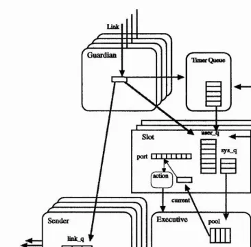
4.3 Message Flow Through The N ode... 55
4.5 Kernel Threads... 56
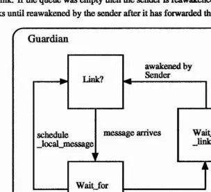
4.5.1 The G uardian... 56
4.5.2 The Timer Q u e u e ... 58
4.5.3 The Executive... 59
4.5.4 The Sender ... 62
4.5.5 D ev ices... 63
4.6 Scheduling in T estbed... 64
4.6.1 Bounded D elays...64
4.6.2 Implementation of Preemption...65
4.7 Initialization... 67
4.7.1 Clock Synchronization...67
4.8 Conclusions... 68
5 Routing 70 5.1 Introduction...70
5.1.1 Finding the R outing...71
5.1.2 Related W o rk ...72
5.2 The Testbed Network Architecture...73
5.2.1 Wormhole Routing ...74
5.2.2 Properties of Testbed N etw orks...74
5.2.3 B roadcast...75
5.3 Deadlock-Free Routing Functions...75
5.3.1 Dependency G ra p h ...77
5.4 Optimality... 78
5.4.1 Routing Optimization... 81
5.4.2 Local M inim a...82
5.4.3 Implementation... 82
5.5 Extending Deadlock Free N etworks...83
5.5.1 Combination Routings...85
5.5.2 Fixed Link Valency Networks...89
5.6 Application to Common Network C lasses...90
5.6.1 Grids and Hypercubes...90
5.6.2 Simple C ycles...91
5.6.3 The T o ru s... 91
5.7 Conclusions...91
6 Monitoring and Background Debugging 92 6.1 Introduction...92
6.2.1 Monitoring...93
6.2.2 Background Debugging...94
6.3 Testing and Debugging...96
6.3.1 C ap tu re...96
6.4 Monitoring...97
6.4.1 Event M onitoring...98
6.4.2 State Monitoring...99
6.4.3 Implementation...99
6.4.4 User Interface to Monitoring... 100
6.5 Avoiding Interference... 102
6.5.1 Exam ple... 103
6.6 Background Debugging... 107
6.6.1 Where to Place the Surrogate...108
6.6.2 Exam ple... 109
6.7 Conclusions... 110
7 Dynamic Modification 112 7.1 Introduction... 112
7.2 The Data Conversion Problem... 115
7.3 Relocating A liases... 118
7.3.1 Assumptions and Definitions ... 119
7.3.2 Conversion Algorithm... 123
7.4 Defining the M apping... 123
7.4.1 Automatically Deriving Field Mappings... 127
7.5 Additional Consistency Tests ... 127
7.5.1 Static Consistency...128
7.6 Generalizations and Practical Considerations... 129
7.6.1 A rrays...129
7.6.2 Different Scalar Types... 130
7.6.3 Pointers in A liases... 130
7.6.4 Deleted F ields...130
7.6.5 Extending the R ety p e... 130
7.7 Data Conversion...132
7.7.1 Exam ple...133
7.8 Pointer Relocation and Conversion of Dynamic Variables . . . 133
7.9 Preserving Consistency of Messages... 137
7.9.1 Aborting a R eload...138
7.10 Related Work ...138
8 Migration 141
8.1 Introduction... 141
8.2 Related Work ... 142
8.3 Synchronous M igration... 143
8.4 Asynchronous Migration...144
8.4.1 Complications...145
8.4.2 Pointer Updating...146
8.5 Correctness Properties... 146
8.5.1 Correctness of Synchronous M igration...146
8.5.2 Correctness of Asynchronous Migration...147
8.6 Exam ple... 148
8.7 Conclusions... 148
9 Conclusions 149 9.1 The Testbed Programming M odel...149
9.2 Im plem entation...150
9.3 Testing and Debugging... 151
9.4 Dynamic Experimentation... 152
9.5 Major Original Contributions...153
9.6 Further W ork... 153
9.6.1 Adding Features to T estbed...153
9.6.2 Device S u p p o rt...154
9.6.3 Heterogeneous System s...154
9.6.4 Using Memory Protection...155
9.6.5 Real-Time Scheduling...155
9.6.6 R o uting ...156
9.6.7 Dynamic Modification...156
9.6.8 Background Debugging...156
9.6.9 Fault T olerance...157
9.7 Closing Remarks... 157
A Testbed vl.O User Guide and Reference 169 A.1 Overview ... 169
A.2 Running the Testbed... 169
A.2.1 Environment S e tu p ...170
A.2.2 Routing Files ...170
A.3 Using T estbed... 171
A.3.1 Testbed Com m ands...171
A.4 Structure of a Testbed Application...175
A.4.1 Message Form at...177
A.4.2 Actions and M odules... 177
A.4.3 User Defined T y p es... 180
A.4.4 Macros for Defining State Variables...181
A.4.5 Static Variables and Functions...182
A.4.6 Configuration... 183
A.5 Detailed Description of Functions...184
A.5.1 Library Functions Available to all S lo ts...184
A.5.2 Host Library F unctions...188
B Testbed System Ports 192 B.l Centre P o rts ...192
B.2 Host Server Ports ...193
B.3 Application Slot P o rts...194
B.4 Common P orts...195
C Source Code for ROV 197 C.l Routing F ile ...197
C.2 C Defittitions...197
Chapter 1
Introduction
Embedded systems are computer systems which are embedded in larger systems and running a single custom application program. Examples range in complexity from systems with a single processor such as video recorders, and disk controllers through more complex systems requiring more powerful processors such as data communications boxes to very complex distributed multiprocessor systems such as chemical plant controllers, robots and space craft control systems. An embed ded system can generally be decomposed into a number of semi-independent state machines or processes each of which may have the following common character istics:
Reactive The process spends most of its time idle, awaiting some event, which may be external (from the outside world) or internal (a message or request from another process). It must then perform some action, possibly within some deadline and return to the idle state.
Periodic The process repeatedly performs the same task at set intervals of time. Each instance of the task may have a deadline relative to its scheduled start. This can be regarded (and will be in the system described) as a special case of a reactive process in which the triggering event is a time.
Tightly coupled to hardware and environment Each embedded system has spe cial requirements which depend on the hardware which is to be controlled (actuators) and the interface to the external environment (valuators). The presence of the external environment in the specification of the system results in complex state spaces which are difficult to predict and model.
have to accept new external events while previous ones are still being dealt with.
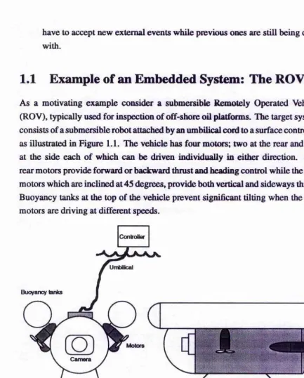
1.1 Example of an Embedded System: The ROV
As a motivating example consider a submersible Remotely Operated Vehicle (ROV), typically used for inspection of off-shore oil platforms. The target system consists of a submersible robot attached by an umbilical cord to a surface controller as illustrated in Figure 1.1. The vehicle has four motors; two at the rear and two at the side each of which can be driven individually in either direction. The rear motors provide forward or backward thrust and heading control while the side motors which are inclined at 45 degrees, provide both vertical and sideways thrust Buoyancy tanks at the top of the vehicle prevent significant tilting when the side motors are driving at different speeds.
Controller
Umbilical
Buoyancy ianks
[image:16.612.56.490.45.584.2]Motors
Figure 1.1: The submersible ROV.
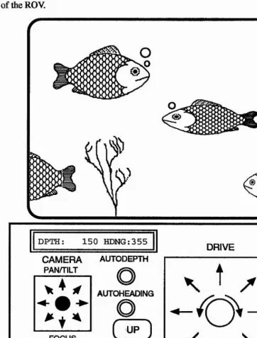
tilt of the camera and buttons for focusing. Figure 1.2 shows the operators view of the ROV.
DPTH: 1 5 0 HDNG:355
DRIVE CAMERA
PAN/TILT
AUTODEPTH
AUTOHEAOINQ
r IN 1
J
FOCUS
OUT
C
UP
DOWN
K
1
[image:17.612.82.444.103.579.2]J
J*
Figure 1.2: Operators view of the ROV.While autodepth (autoheading) is selected the control software attempts to maintain depth (heading) at the value reported by the depth gauge (compass) when this mode was entered. Autodepth control is temporarily overridden while one of the up or down buttons is depressed and restored when released with the target depth reset to the current depth. Similarly autoheading is temporarily overridden when the drive joystick is twisted to turn left or right and restored when it returns to its normal position with the target heading reset to the current compass value.
damage to the hardware:
1. There is an upper bound on the rate of change of speed of each motor.
2. Each motor must be brought to a stop for a short period before changing direction.
3. There is an upper bound on the sum of speeds of the two motors on each side of the vehicle.
The software is divided into two layers. The low level control performed onboard the vehicle consists of switching each motor (including those which control the camera) on or off for a percentage of a duty cycle specified by the high level control software which resides in the surface controller. The onboard software also polls the depth and compass gauges periodically and reports the values back to the surface controller. The high level controller is responsible for converting operator commands into appropriate motor values and for the autodepth and autoheading control while maintaining the safety conditions, as well as displaying the reported depth and compass values.
The original version of the ROV control software was implemented in Z80 assembly language with the only software testing done on the vehicle. Any behavioural faults meant hauling the robot up to the surface, trying to debug the assembly language program, re assembling the new control code, burning new eproms, and trying again. In Section 2.10 an implementation of the ROV in the Testbed programming model described in Chapter 2 is presented.
1.2 Approaches To Embedded System Construction
of resources, it may be acceptable simply to reconfigure and restart the application or even reboot the system if the fault lies there (e.g., memory fragmentation). This is generally not acceptable in an embedded application/system. Most work on embedded systems appears in the real-time systems literature, however there are other important issues which deserve study such as the general development and debugging problems which this work addresses.
Two approaches to embedded system construction are to program the hardware directly or to use an operating system. The advantages of the former are that it is theoretically possible to minimize hardware requirements such as memory and processor performance. This is probably £q)propriate for the simplest embedded applications where these resources are most limited. The main disadvantage of the direct approach is high software costs; the code is likely to be hard to understand, debug and modify. These become r^idly worse as the complexity of the application increases. Operating systems have die advantage of code reuse, the application programmers task should be easier and the resulting code should be simpler, as much detail is hidden in system calls. The operating system may well provide facilities and tools which make the system easier to develop, debug and modify, such as the ability to test outside the target environment using simulations of the real system. The disadvantages of an operating system include the excess baggage in terms of memory and processor performance requirements, possible loss of control of resource management and the fact that the applications programmer may not be able to obtain detailed information about the behaviour of the system and the consequences/side-effects of system operations. This last difficulty makes verification of the system difficult and also hinders debugging as the programmer may be unsure of whether a bug is in the system or application code. Often such cases arise from a lack of understanding of the operating system’s behaviour due to poor documentation.
the programmer to work around inappropriate low level mechanisms which add unnecessary overhead. For example it is often not possible for the application to control low level scheduling or inform the system of its timing constraints. The microkernel approach currently in vogue in operating systems design (Amoeba, Mach 3.0 [97]) helps to some extent, however most of these systems have been developed with different objectives to embedded systems operating systems such as implementing a better (e.g., distributed, object oriented) Unix.
An operating system designed specifically for embedded applications should overcome most of these difficulties. Obviously due to the highly disparate nature of embedded applications, it is hard to produce an operating system which is ideal for all and there will always be resource penalties to pay for using one. However for complex embedded applications the benefits should outweigh the costs.
In addition to the attributes of predictability, simplicity and configurability of the kernel, an operating system for embedded systems can also provide higher level features which aid in the development process. These are outlined in the next section which overviews the goals of the Testbed project.
1.3 Goals of the Testbed
Monitoring It is essential that both the whole system and individual ruiming processes can be monitored during their operation. Monitoring inevitably causes perturbation of the target system (called the “probe effect” in [28,40]). It is important to minimize this effect, and allow the test bed to eavesdrop on the target system as silently as possible. Embedded systems are almost always time-critical. Timing is one of the most delicate aspects of the target system behaviour, making silence a difficult criterion to meet and effectively ruling out interpretive debugging.
processes.
Process Interconnection In order that a client application interconnection topol ogy can be designed independently of the physical network topology, it is necessary to provide a communication harness that supports a single system wide communication model. This model must provide, as simply and efficiently as possible, deadlock-free, versatile and reliable routing of messages.
Process Migration Time criticality makes the allocation of processes to proces sors an important issue, and the test bed must also provide for dynamic control over this allocation by allowing processes to be migrated. Migra tion is another reason for having the system wide communication model. Migration can be viewed as a form of dynamic modification.
Background Debugging Interactive debugging creates a bottleneck, which causes excessive intrusion and contributes to the probe effect mentioned above. One way to minimize the interaction bottleneck is by means of background debugging in which debugging decisions and actions are devolved as far as possible to code which runs alongside the application software.
1.4 System Overview
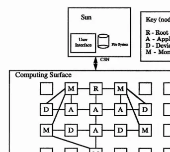
Testbed is currently implemented on a Meiko Computing Surface connected to a Sun workstation. The reconfigurability of the Computing Surface makes it easy to experiment with different interconnection topologies for multiprocessor embedded applications and also provides extra processors which can be used for simulating devices and off-loading monitoring tasks (as suggested in [1] and [33]), reducing interference which might otherwise change the behaviour of the application.
Key (node types): R - Root
A - Application D - Device M - Monitoring
Computing Surface
□
^
□ □
M\
m\^
□
|
a
P
□
(
d
V
-4 ^ □
[image:22.612.88.430.66.372.2]□
□
□
Figure 1.3: The Testbed development platform supports “in vitro” development with extra nodes used for monitoring and simulating external devices.
1.5 Related Work
1.5.1 Embedded Systems Development Environments
A number of test beds and development environments for embedded systems have appeared in the literature recently, most with some features in common with Testbed. However none have all the features described in this thesis. In particular dynamic modification facilities are either absent or much more primitive than those described in Chapter 7.
mined point in time. By contrast. Testbed is an event-triggered system in which the scheduled start time for a time-dependent action is an event.
Similarities in the work described in [83] include the use of passive monitoring rather than interactive debugging to avoid the probe effect and the use of extra processes and processors for environment and device simulation.
[33] describes testing in a “host” environment with device handlers replaced by device simulators for testing the logical function of the system and also in the target system with an environment simulator for testing performance. The environment simulator runs on an external system to avoid perturbing the software under test
1,5.2 Concurrent Debugging
The same techniques which are used for debugging sequential programs may be used to debug concurrent ones, both to detect the same types of bugs and also new ones introduced by communication, such as sequencing errors. In the latter case the efforts of the debugger are often thwarted by the intrusiveness of the debugging process—the probe effect, in which the very presence of the debugger alters the timing properties of the program to mask possible errors. Detecting the special errors which are introduced due to concurrency, and avoiding the probe effect, have led to approaches which concentrate on specific aspects of debugging, or one technique (such as message monitoring).
[60] surveys techniques for debugging concurrent programs and identifies four classes:
1. Traditional debugging techniques. 2. Event-based debuggers.
3. (Graphical) tracing techniques. 4. Static analysis.
Here debugging techniques will be divided into the following (non-mutually exclusive) categories:
Interactive Debugging In which the user may view and interact with execution of the program in real-time.
Monitoring In which the events/states in the system are captured, and viewed/used either in real-time or post-mortem.
Static Debugging Where a specification of the program is checked against certain assertions about its valid behaviour.
Background Debugging In which monitoring techniques are used in conjunction with the assertion idea from static debugging to automate the process of interactive debugging.
1.53 Interactive Debuggers
Conventional source level debuggers are a very useful tool in software develop ment. Unfortunately many systems which support and even encourage concurrent programming, fail to provide interactive source-level debuggers which support multi-threaded programs. For example the dbx and dbxtool debuggers in SunOS and the tdb and tdbtool debuggers for the Meiko Computing Surface cannot cope when a process forks (or PARs), although there have been interactive windows- based debuggers for some time [27,40,48,80,89] which do support multithreaded programs.
1.5.4 Replay
1.53 Static Debugging
This approach generally involves converting a high level specification into a graph, such as in the Petri net approach [21] which may be analyzed to detect potential invalid communication patterns such as deadlock. Unfortunately for realistic systems the graphs quickly become unmanageable.
[41] describes a method for testing a set of communicating sequential pro cesses, by attempting to construct a feasible sequence of interactions between them from a given set of inputs by an iterative algorithm which initially assumes random inputs to each process. This approach may be suitable for short processes of finite duration, however the artificial time ordering of the communications used may not reflect what happens in the real system.
The research described in this thesis has focused on providing mechanisms to facilitate non-intrusive debugging which is not possible with source level, break point techniques. Consequently Testbed does not provide these facilities. A survey of work on non-intrusive monitoring and background debugging can be found in Chapter 6.
1.6 Thesis Structure
The rest of this thesis is structured as follows: Chapter 2 describes the programming model around which the Testbed is buUt Examples are presented to illustrate the use of this model.
Chapter 3 gives details of the higher levels of system software which provide the debugging support and implement the programming model.
Chapter 4 describes the design of the BED (Basically Event Driven) multi threaded kernel which supports the Testbed programming model.
Chapter 5 presents work done in support of Testbed on deadlock-free routing in networks.
Chapter 6 describes the monitoring features of Testbed and discusses how they may be used to debug and tune an embedded application without interfering with the application’s behaviour.
Chapter 7 contains a formal treatment of the solution to the pointer updating problem as well as a general description of the mechanisms which support dynamic modification in Testbed. A simple example is provided which illustrates how dynamic modification may be used in practice.
Chapter 9 summarizes the project and its contribution.
Appendix A gives a detailed description of the user’s view of the current Testbed implementation. Appendix B gives details of system port assignments and Appendix C gives source code for the examples described in the main body of the thesis.
1.7 Original Contribution
The original aspects of this work include:
1. The programming model (Chapter 2), which differs from the CSP style commonly used for distributed memory systems and is better suited to the reactive nature of embedded systems.
2. The integration of time into scheduling (Chapter 4).
3. Work on optimizing message routing while preserving deadlock-freedom and extending networks with such routings in a regular way (Chapter 5).
4. Monitoring and background debugging (Chuter 6). The structure of Testbed programs provides natural breakpoints which enable non-intrusive monitor ing and provide support for background debugging.
5. Dynamic modification (Chapter 7) and Migration (Chapter 8). The struc ture of the Testbed system and applications also allows some of the most difficult problems in these two fields to be solved. Much more flexibility in data structuring and a greater degree of automation of data conversion are provided than with previous work in the field of dynamic modification.
Chapter 2
The Programming Model
2.1 Introduction
Testbed is based around a distributed reactive processing model in which events are synonymous with messages. The processing entities are known as slots which are active objects consisting of encapsulated state data and code for processing and responding or reacting to messages. Slots may reside on the same processor or different ones separated by a network. In both cases communication is identical from the slot’s viewpoint and any slot may send messages to any other without the need to establish a connection. Events may originate outside the system via a device interface or inside when one slot sends a message to another. Similarly a slot sends messages to a device as if it were another slot. When a slot receives a message it is processed by a unit of code called an action. This is a procedure which may update the slot’s state in response to the message and any data it may contain and respond by sending new messages. Actions always terminate and do not perform input Instead new messages are processed by new action instances. Only one action can be in progress at a time in any slot. The slot’s state includes a table mapping ports to actions. Each message contains a port identifier and the system uses this to index the port table and determine which action to invoke to process the message. This port assignment may be altered by actions. Time is intrinsic to the model in that each message carries a timestamp which, if in the future, can be used to delay a message. Also a slot can have a deadline for processing each message which the system uses to schedule multiple slots on a single processor.
but with a framework for the software. Specifying embedded software using the Testbed model involves breaking the system down into components which form the slots, determining the types of messages which these components need to send and respond to, and designing the ports and associated actions required to receive and process these messages. This resembles the state machine network approach often used in the higher levels of embedded systems design [86]. In fact state machines map naturally onto slots with events corresponding to messages, states to the combination of state data and port settings and state transitions to the operation of actions on the state triggered by the events. The event-action model also greatly simplifies and modularizes the implementation of the monitoring and debugging activities of Testbed. If the user were to provide a complete process then Testbed would be forced to probe at its inner workings from the outside. This would require a great deal of work at the compilation stage and would be especially difficult if the process had multiple threads.
The Testbed programming model is supported by a kernel described in Chap- ter4 which transports messages between slots and performs scheduling operations. The rest of the Testbed’s application and debugging support is implemented using slots and actions. Each processor has a centre slot which performs housekeeping activities and a special version of this slot residing on the root processor provides the user interface via the Unix host using the X Window System and Athena Widgets [71]. This is referred to as the host server slot.
2.1.1 Platform and Language Issues
Although Transputers were chosen as the platform for Testbed, the programming model is not Transputer specific and in fact differs greatly from the CSP/occam model [43, 103] normally used to program these systems^. Transputers are an appropriate platform for Testbed as they were designed for both embedded systems and multiprocessing applications. Testbed is aimed at multiprocessor embedded systems and the availability of Unix workstation hosted Transputer arrays such as the Meiko Computing Surface allow the software to be developed and tested on the same processor as the target system.
Given the event-action model, the choice of programming language had to be made. The obvious choice for Transputers is occam, however the fact that actions are sequential and are not permitted to perform blocking input would mean that the programmer would be restricted to a sequential subset of occam without the input operations. It was decided that it would be better to use a purely sequential
language for the actions and since C is also in common use for writing embedded systems software both on Transputers and other platforms, it was chosen.
2.2 Action Semantics
Actions are simple functions which are called by a special harness process. All actions are invoked with the same parameters. A C prototype for an action would have the form:
void action(void *data);
The parameter is a pointer to the data contained in a the message (if any). System functions are provided for obtaining information from or even a complete copy of the message header. This is useful for reasons such as identifying the sender, checking for expiration of the deadline or rescheduling the message for a later time.
Actions may send messages to other slots, to the same slot or to an external device, but may not perform input This property reflects the view of action functions as interrupt handlers, which should execute for a short bounded period (without interruption). If blocking input needs to be performed from an external device, it will be performed by a special input handler process which is considered to be part of the system rather than application code. When a new message arrives it is placed by the system into a FIFO queue for the destination slot. When space for messages becomes exhausted, messages are discarded. It is up to the application designer to ensure that there is always enough space for the maximum number of messages which may be waiting at each slot
2.3 Message Semantics
When sending a message, the sender provides the following parameters:
Destination The destination slot id.
Size The size of the message data.
Port An indication of the type of message to the destination slot.
Timestamp A time before which the message must not be processed at its desti nation.
The application does not need to know on which processor the destination slot is, though this location is specified by the user during initial loading and may change during development as slots are migrated to tune performance. The message is automatically routed to the correct node as described in Chapter 5.
The queue of messages for a slot will be referred to as its schedule. Once a message has reached the head of this queue it will eventually be removed and an action will be dispatched to process it At this point it is no longer part of the schedule and carmot be overwritten by newly arriving messages.
When a message arrives with a timestamp which is greater than the processor’s local clock value, its arrival is delayed until this time has past. Then the message is added to the back of the queue for that slot as if it had just arrived. Each slot also has a post time which is added to the timestamp to give a deadline before which the system should action the message if possible. In cases where no particular deadline is appropriate, a priority may be given. The deadlines and priorities are used by the system to choose between different slots on the same processor. This scheduling is described in Section 4.6. The destination slot has a port table which contains a mapping from the port contained in the message to an appropriate action. This mapping may be changed by the application.
It is possible that an overload situation may arise in which messages need to be discarded. To avoid losing crucial messages, the application may specify a minimum number of buffers which are reserved for use by messages destined for a particular port. On the other hand it may be known by the system designer that cer tain types of messages are liable to flood the system in exceptional circumstances and so it is possible to specify a maximum number of such messages which may be waiting to be processed at any one time, so protecting other more important messages from being lost When a message arrives and the slot currently has the maximum number of messages for that port its data field is used to overwrite the data of the most recently arriving message. This mechanism is also useful as an optimization for update messages when only the most recent message is of interest. For example a device may periodically report the current value of some valuator. There is often no need to store several such messages so the maximum value can be set to 1.
precedence. This attribute also provides a mechanism for responding to device or timer interrupts deterministically.
2.4 Devices
In keeping with the rule that actions cannot block awaiting input, synchronous devices, such as those attached to Transputer links or which indicate readiness via the event pin, are handled by kernel threads which convert incoming data into Testbed messages. There are also kernel threads which convert Testbed messages into raw data sent to the device. Since the input data does not arrive in the form of Testbed messages the destination slot and size of the data need to be specified by the application in advance. Also the application needs some way of addressing the device. Device links, as well as raw links^, are specified as part of the network description^ at which stage they are given slot identifiers. Any slot can send a message to a device as if it were an ordinary Testbed slot. Two function calls are provided to configure the kernel thread which inputs from the device, telling it the size of the incoming messages and which slot and port to deliver them to. The co n f ig u re _ d e v ic e function causes messages of the given size to be read repeatedly and passed on to the given slot and port, while the re a d _ d e v ic e function results in a single message being delivered. In this way slots anywhere in the network can access any device transparently and input from the device can be routed to a receiving slot on any processor.
Asynchronous devices, such as memory mapped, polled devices do not need to be part of the kernel. Application actions can read and write them directly as this does not involve blocking. If access from multiple slots or from remote nodes is required to such a device then a dedicated slot can act as a device driver, but this is part of the application, not part of the system.
2.5 System Library
A set of library functions is provided to be called by applications. These include a subset of the standard C library functions as well as many Testbed specific calls which provide features such as communication, memory management and port management. A full explanation of these functions along with some useful macros which are provided in header files, can be found in Appendix A.
^useful during development, so that a (tevice may be simulated by a Testbed slot on a separate processor
2.6 Initializing Applications for Testing
When the application is ready to be installed on the target system, it will usually be linked with those parts of the Testbed system which are required to support its execution into a set of executable modules which can be loaded from disk or stored in ROM. However during development on the Computing Surface the Testbed system, including its user interface is loaded first using the Meiko system configuration and loading facilities (CSBuild [61]) and then the application is loaded by Testbed.
At system creation time, the physical network of processors, together with routing tables are supplied by the user. The target application is composed of a collection of slots which are assigned to physical processors (not necessarily one-to-one). There is no special compiler for Testbed. Instead the one which comes with the system (e.g., the Meiko C compiler) is used. The source code is divided into modules which are loaded as units. There are three types of mod ules, declaration modules, initialization modules and application modules. Each declaration or initialization module contains a declaration or initialization func tion which is called after the module is loaded. Declaration functions define user defined types, state variables and the initial port assignment for the slot. Variables can be given initial values when first defined. Initialization functions contain extra initialization which needs to be performed at system startup. Application modules do not contain a function which is invoked when they are loaded. Any of the three types of module can contain actions and other functions called by them, however the declaration and initialization modules may not call functions in application modules or declaration and initialization modules which are loaded after them. Nor may they refer to variables declared in these later modules. This is because declaration and initialization modules are linked immediately, and invoked, while the application modules are not linked until the end of the load process. The system is bootstrapped by means of a special initialization function executed on the host server. This function makes system calls to create and initialize all other slots in the system. The initialization of these slots is performed by loading the declaration, initialization and application modules which define them.
Type definitions and static variables are generally created by declaration functions which are invoked once when the application starts up or during a reload operation. Such reloads are the means by which the incremental modification occurs.
2.7 Programming Interface to Data and Types
Both types and state variables are currently defined using procedures and macros from declaration functions^, in the case of static variables, or from action code in the case of dynamic variables. A set of standard types is predefined and these form the basis for the user defined types. With the exception of arrays and pointers, each state object must have a type corresponding to a definition in the type table. This means that all structures must be defined explicitly as types in the type table before being used (equivalent to having to typedef each struct used in a C program). Variables may be declared as pointers to, or arrays of, existing types (or pointers, arrays etc.). This results in all intermediate pointer and array types being added to the type table. The naming convention for these types is based on C syntax. A pointer to base_type is named base_type*, while an array of n base-types is named base_type[n]. For multiple dimensional arrays the dimensions are ordered from right to left So base-type[n] [m] is an array of n base_type[m]. Pointers and arrays may be combined. For example if a variable is declared of type int*[3]**[4][5], (with int already declared) then this results in the following types:
int* int*[3] int*[3]* int* [3]** int*[3]**[5] int*[3]**[4][5]
In words the final type is: array of 4 array of 5 pointer to pointer to array of 3 pointer to int. It is not clear whether this is the best convention intuitively since to completely dereference a variable of this type called x, you might say: *(**x[3][4])[2]. Note that these declaration conventions do not exactly implement the C declaration conventions which are more general and involve brackets. They are used because such expressions are easier to parse than general C type specifiers.
Unions are not currently supported.
2.8 Dynamic Memory Allocation
Dynamic variables may be created at any time by using the same functions as are used for defining static variables in declaration modules. They are distinguished by having a NULL name value. Both dynamic and static variables are stored in the symbol table and are converted during dynamic modification and copied during a migration.
The standard C library malloc and free operations take non-deterministic times, which make them unacceptable for a time critical embedded application. It is also possible that the heap may become fragmented so that requests for storage may fail after the system has been running for some time which is also unacceptable. For these reasons a free storage management scheme based on memory pools is used. The free store consists of a set of pools of free blocks of the same size, with one pool per block size. Allocating a new block consists of searching for the first pool (the pools are kept in a size ordered list) which has a free block large enough and deleting the first element (constant time). Since there is a small fixed number of pools, there is a small upper bound on the time for an allocation. Storage for messages also needs to be allocated dynamically and so a similar mechanism is used as for state variables. As the management of the schedule is performed by the kernel concurrently with the action, there needs to be a separate set of pools for this, known as the system store. Although the system heap allocation/deallocation is only performed by the kernel, the user can specify the heap configuration at slot creation time.
When a slot is created, arrays of pool specifiers are provided for the system and user stores. Each pool specifier consists of the block size and the number of blocks of that size. The system uses this information to initialize the two free stores. A default store configuration is provided so that the user can omit the specification initially. Section 3.3.5 describes the implementation of the heap.
2.9 Development Support Environment
2.9.1 Simulating Hardware and Environment
The concept of simulating external devices using separate processors is suggested in [33] as a way of avoiding perturbing the software under test. This works particu larly well with transputers as the external devices are likely to be attached through the same link interface which is used to communicate with other processors. For tunately these simulation problems have much in common with embedded systems and Testbed is well suited to implementing them. Simulating devices and envi ronment on separate processors from the application also provides an opportunity to perform monitoring on these processors, which does not interfere with the per formance of the application system, although care is still needed to ensure that it does not interfere with the performance of the simulation.
2.9.2 Using Separate Processors to Reduce Monitoring Over
head
The presence or absence of monitoring software can cause differences in behaviour of the system being monitored, known as the probe effect. Off-loading some of the work involved in monitoring onto separate processors can alleviate the problem. This is the approach taken in [1], where an efficient breakpoint mechanism is used to capture information and pass it to a separate processor where analysis, filtering and logging or reporting back to the user are carried out, while the application is allowed to proceed with minimal interference.
2.93 Using Extra Routing Nodes to Avoid Interference
2.10 Example: Implementing the ROY
The Testbed is particularly suited to the development of reactive embedded sys tems. The programming model described in this chapter is illustrated with the control software for the submersible Remotely Operated ^fehicle (ROY) described in Section 1.1. More than one possibility exists for nuqpping the control sys tem onto slots. One possibility is to have three slots on two processors, one for the high level control functions which are performed by the surface control module, which has its own processor and two for the low level onboard control functions and status reporting on the other processor. These wül be referred to as fflGH-CONTROL, LOW.CONTROL and FEEDBACK. Initially it will be as sumed that there is a HOST slot which converts operator commands into messages to the HIGH-CONTROL slot and to which the depth and compass values are re ported and an ROY device which accepts motor on/off and direction values from the LOW-CONTROL slot, without acknowledging and requests for the current depth or compass value from the FEEDBACK slot which result in a reply. Later the method of implementing a user interface and a simulated ROY for testing will be explained. The camera control involves exactly the same sorts of messages and actions as the driving of the vehicle, except that there is no feedback within the system (the video signal is carried back to the monitor by a separate cable). It has been omitted from the implementation described here for simplicity.
2.10.1 Notation
Testbed programs will be described in an Algol-like pseudocode form. For each slot the actions, ports, outgoing messages and pseudocode are presented followed by initialization code. For the ports and messages only the fields which take non-default values are specified. Full C versions of the examples can be found in Appendix C. When a value such as the action corresponding to a port is constant it is indicated using an =, whereas if it may change := is used.
2.10.2 HIGHXONTROL
Actions and Ports
This slot receives separate heading, horizontal and vertical velocity commands from the HOST slot (coming from the joystick and up/down buttons respectively). These are handled by the Heading, H_Velocity and V_Velocity actions. Messages which change the autodepth and autoheading status are handled by the
message types is of interest, so the corresponding port entry has the max field set to 1 in the following port definitions:
h_velocity [action = H„Velocity; max = 1; data = horizontal_velocity] v_velocity [action = V_Velocity; max = 1;
data = rate]
heading [action = Heading; max = 1; data = differential] autodepth [action = AutoDepth; max = 1;
data = status]
autoheading [action = AutoHeading; max = 1; data = status]
The slot also receives messages carrying depth and compass values from the on board processor. These are normally handled by the H o ld _ D e p th and H o ld _ H e a d in g
actions except when entering or resuming autodepth or autoheading mode when the target depth or heading is reset using the Z ero__D epth or Z e r o _ H e a d in g
actions. As with the messages from the HOST slot only the most recent is relevant, so max is set to 1:
depth_report [action := Hold_Depth; max = 1; data = depth]
heading_report [action := Hold_Heading; max = 1; data = coupass]
Note that the HIGHjCONTROL slot is entirely reactive. It only performs
actions in response to messages from other slots with no periodic activity scheduled from within the slot. However since the LOW_CONTROL slot described below periodically sends the depth and compass values, this imposes a periodic behaviour on the HIGH-CONTROL slot.
Outgoing Messages
Messages are sent to the LOW-CONTROL slot of the form:
UPDATE_MOTOR [dest = LOW_CONTROL; port = update_motors; data = new_motor_settings]
and status messages containing the latest depth and compass readings are sent to the HOST slot:
Actions
The actions in this slot make use of the utility procedure ad j us t_motor s which computes new target motor speeds, changes the value of each motor in the direction of the target speed within the safety constraints® and sends UPDATE_MOTOR messages for motors which have changed. If condition 3 would be violated by the new motor settings, then the speed of each motor is reduced to 75% repeatedly until the sum of each of the two motor speeds on each side is within the required limit. The autodepth and autoheading control are performed by the auto_vertical
and auto_turn functions. These functions may be found in Appendix C. Heading messages contain a differential value in the range [—100,100], de rived from the position of the drive joystick twist grip, which is the difference between the right and left motor values. A positive differential will thus pro duce a left (anticlockwise) turn which is consistent with compass values. The
rear_di f f erent ial value is used by ad j us t_motors, while manual_di f f
is set to indicate that manual heading control is in operation. If the grip position has returned to the neutral zero position and autoheading control is engaged, the action for the heading_report port is set to Zero_Heading so that the next reported compass value will be taken as the new target heading for autoheading control.
Heading(differential):
manual_diff := differential; rear_differential ;= manual_diff; adjust_motors;
if manual„diff = 0 and autoheading_mode then heading„report.action ;= Zero_Heading.
The horizontal velocity has both sideways (positive to the right) and forward components each in the range [—100,100]. These values may be changed inde pendently of autodepth or autoheading control.
H_Velocity(horizontal„velocity):
velocity.right := horizontal__velocity.right ; velocity.forward := horizontal_velocity.forward; adjust_motors.
The vertical velocity can be —100,0, or 100 corresponding to up down or stopped respectively. The manual_v variable is set to indicate that manual depth control
is in operation. If the rate received is zero this indicates that the button has been released and if autodepth control is engaged the action for the d e p t h _ r e p o r t
port is set to Z e r o .D e p t h so that the next reported depth value will be taken as
the new target for autodepth control.
V_Velocity(rate);
manual_v := rate;
velocity.down := manual_v; adjust_motors;
if manual_v = 0 and autodepth_mode then depth_report.act ion := Zero_Depth.
The autodepth and autoheading messages contain on or off status values. When one of these modes is selected, the appropriate port is set to the Zero action to set the target to be maintained.
AutoDepth(status):
autotdepth_mode = status; if autodepth_mode then
depth_report.act ion ;= Zero_Depth.
AutoHeading(status):
autoheading_mode := status; if autoheading_mode then
heading_report.act ion ;= Zero_Heading.
The Zero actions set the new target to the reported data and revert to the Hold action. If auto mode is set and manual override is not in effect the Hold actions compute new target velocities. Otherwise they just use the targets set by the operator. Only the H old_H eading action adjusts the motors and reports the status to the HOST slot as there M always a heading report following each depth report from LOW_CONTROL in each duty cycle.
Zero_Depth(depth):
target_.depth := depth;
depth_report.act ion := Hold_Depth; status.depth ;= depth.
Hold_Depth(depth):
if manual_v = 0 and aut odep th_mode then
velocity.down := auto_vertical(target_depth - depth); status.depth ;= depth.
Zero_Heading(compass);
target„heading := conpass;
heading_report.action := Hold_Heading; status.compass := compass;
Send(STATUS_REPORT).
Hold_Heading(compass):
if manual_diff = 0 and autoheading_mode then
rear_diff erent ial := aut o_t urn (targe t_heading - compass); adjust_motors ;
,}
status.compass ;= compass; |
Send(STATUS_REPORT). !
1
’■J: No initial messages need to be sent from this slot so initialization consists of setting j the state variables to their default values. | i
Initialisation: |
4
manual_v := 0 ; |
velocity := {0,0,0}; j
manual_diff ;= 0; |
rear__di f f erent ial := 0; ]
autodepth_mode := FALSE; |
aut ohe ading_mode ;= FALSE; j
zero_target_speeds. |
2.103 LOW CONTROL
I
I
This slot has a duty cycle during which it switches each motor on for a percentage 1i
of the cycle given by the speed. {
Ï Actions and Ports
'I
non-zero are switched on at the start of the duty cycle by the Switch_On action which also schedules SWITCH_OFF messages. The port definitions are:
update_motors [action = Update_Motors; max = 1; data = new_motor_settings] switch_on [action = Switch_On]
switch_off [action = Switch_Off; data = motors_off; critical]
Note that the sw i tc h _ o f f port is critical as if it is delayed, the motor will stay on for too long.
Outgoing Messages
MOTORS_ON [dest = ROV; data = motors_on] MOTORS_OFF [dest = ROV; data = motors_off] MOTORS_PLUS [dest = ROV; data = motors_plus] MOTORS_MINUS [dest = ROV; data = motors_minus] SWITCH_ON [dest = LOW_CONTROL; port = switch_on] SWITCH_OFF [dest = LOW_CONTROL; port = switch_off;
data = motors_off]
Actions
The motor settings from the HIGHXONTROL slot are stored to be used by the
Switch_On action.
Update_Motor (new_motor_settings) :
motor_settings := new_jnotor_settings.
All motors whose speed is non-zero are switched on by the Switch_On action. This also sets the direction and schedules SWITCH_0FF messages. If several motors have the same speed then only one message is scheduled to switch them all off. If a motor speed is 100% then it is left on until the next duty cycle. The last Switch_Of f action in each duty cycle reschedules the next SWITCH_ON
message unless there are none, in which case it is scheduled by Swit ch_On. The
Switch_On action is also responsible for advancing the next_duty_cycle
variable. The while loop ensures that if there is an unexpected delay of some kind which causes one or more cycles to be missed, the missing cycles are simply skipped.
while next_duty_cycle < Now do
next_duty_cycle := next_duty_cycle + duty_cycle; motors_on.set := motors_plus.set
:= motors_minTis. set := EMPTY_SET; for i := 0 to nmotors-1 do
begin
speed = motor_settings[i] .speed; if different_speed(i) then
begin
motors__off.set := EMPTY_SET;
add_motors_with (speed, motors__of f ) ; if speed < 100 then
begin
delay SWITCH_OFF by duty_cycle * speed/100; on_count ;= on_count+l
end end;
if speed > 0 then add {i, motors_on ) ;
if motor_settings[i].direction = 1 then add ( i, motors_plus )
else
add {i, motors__minus ) end;
Send(MOTORS_PLUS); Send (MOTORS__MINUS) ; Send(MOTORS„ON) ; if on_count = 0 then
Schedule SWITCH_ON for next_duty_cyc 1 e .
Switch_Off (motors__of f ) ;
Send(MOTORS_OFF);
on_count := on_count-l; if on_count = 0 then
Schedule ( SWITCH_ON, next_duty__cycle ) .
The initialization of tins slot involves scheduling the first SWITCH__ON message.
Initialisaton:
next_duty_cycle := Now + duty_cycle; initialise_motor_settings;
on_count ;= 0 ; set_priority(0);
Schedule ( SWITCH_ON, next_duty__cycle ) .
Note that the priority for this slot is set to the maximum (0) which means that it will always be scheduled in preference to the FEEDBACK slot.
2.10.4 FEEDBACK
This slot polls the ROY device for the current depth and compass values which are reported to the HIGH_CONTROL slot.
Actions and Ports
Periodic polling is initiated by the P o ll_ D ep th action (which requires no data). The depth and compass messages returned are handled by the R eport_D epth and R eport_C om pass actions.
poll_depth [action = Poll_Depth]
status [action := Report_Depth; data = status_value]
Outgoing Messages
DEPTH__REQÜEST [dest = ROV; data = depth_request] COMPASS_REQUEST [dest = ROV; data = compass_request] POLL_DEPTH [dest = FEEDBACK; port = poll_depth]
DEPTH_REPORT [dest = HIGH_CONTROL; port = depth_report; data = depth]
COMPASS_REPORT [dest = HIGH_CONTROL; port = compass_report; data = compass]
Actions
reply. This action reports the compass value to HIGH-CONTROL and schedules the next poll for the start of the next duty cycle.
Poll_Depth:
Send(DEPTH_REQUEST);
status.action := Report_Depth.
Report_Depth(status_value) ;
depth ;= status__value; Send(DEPTH_REPORT); Send(COMPASS_REQUEST);
status.action := Report_Compass.
Report_Compass (status__value) :
compass := status_value; Send(COMPASS_REPORT);
Schedule (POLL_DEPTH, next_duty_.cycle) .
The initialization of this slot involves scheduling the first POLL_DEPTH message and configuring the ROV device to pass messages of the correct size to the FEEDBACK slot, status port.
Initialisaton;
duty__cycle := DEFAULT_DUTY_CYCLE ; next__duty_cyc 1 e := Now + duty_cycle;
configure_device (ROV,status_value_size,FEEDBACK, status) ; Send(POLL_DEPTH).
2.103 Notes
control would suffer, so it might become necessary to sacrifice small variations in the motor speed. This effect can be achieved through the use of deadlines rather than fixed priorities for both the FEEDBACK and LOW_CONTROL slots.
2.10.6 Testing the ROV
So far only an implementation of the application part of the ROV control software has been described. In order to test the software in vitro, both the ROV control console (the HOST slot) and the robot itself need to be simulated. The serial cable which cormects the surface controller to the on-board controller may also be simulated. The console, the robot and the serial link are each simulated on a separate processor by a Testbed slot Figure 2.1 shows the configuration of slots and processors in the development architecture.
Note that the introduction of the CABLE slot requires modification to the implementation presented above to convert between the raw links and the slots at each end of the cable. Details of the customization of the Testbed user interface are presented in Chapter 3.
Device and Environment Simulation
The ROV device and environment simulation are provided by the ROV slot which resides on a separate processor attached to the processor containing the FEEDBACK and LOW-CONTROL slots by a raw link. To the application it appears exactly as if this link is coimected to the real ROV hardware interface via a link adaptor. At a later stage in the development it would be possible to replace the raw link and the processor performing the simulation, with the actual hardware, without the application software needing to change in any way as a device link is indistinguishable from one end of a raw link. All that would be required would be a change in the network configuration file.
A raw link is accessible to the application via two device ids, one for each end, which are equivalent to slot ids, but must be specified in the configuration file. In this example the application end of the link has id ROVJDEV, and the simulated ROV end has id CONTROL-DEV.
Link to Host System
HOST (interface)
HIGHCONTROL
Raw Link Testbed lin k
[image:46.612.71.451.74.490.2]c
c
LOW CONTRC».Figure 2.1: The ROV development architecture.
key which identifies its type. Each time a message arrives the current values of the depth and compass are updated by calculating the vertical velocity® based on the current states (on or off) and directions of the side motors then multiplying this by the time which has elapsed since the last update. An environmental component is added to the velocity to simulate the effects of currents, buoyancy of the vehicle etc. The compass is updated in a similar way except that the difference between the directions and states of the rear motors is used. Full C source code for the ROV slot is given in Appendix C.
2.11 Related Work
Most programming systems oriented towards development of real-time systems are based on conventional sequential processes, for which a scheduler [74, 79, 93] or communication model is provided [58]. Often in fact these systems are implemented in a Unix or similar environment, in the form of a light-weight threads package [36, 84].
Spring [92,93] is implemented on a special architecture consisting of a num ber of SpringNet nodes coimected by an ethemet for non-ieal-time traffic and a fibre optic ring connecting 2 Mbyte memory boards on each node providing repli cated memory with predictable performance for real-time communication. Each node consists of a number of 68020 processors divided into system processors which perform scheduling operations and application processors which execute previously guaranteed application tasks. Although such a separation between time-critical and other work onto separate processors is not intrinsic in Testbed, it is supported by the global communication model. The Spring programmer sees a set of conventional processes containing critical sections and both synchronous and asynchronous communications which may be grouped to form a process group with a single timing constraint These processes are transformed by the compiler into a set of execution units called tasks. The Spring kernel contains support for a wide variety of different task attributes. Testbed messages and their associated ac tions form the equivalent of tasks, but have much simpler attributes. This is not to say that a more complex mechanism may not be buüt on top of the simple Testbed scheduler in a layered fashion. The problem with a model such as the Spring one which hides the underlying scheduling units from the programmer/developer is that debugging and performance tuning become more difficult The Testbed programmer is fuUy aware of the units of scheduling and yet does not lose the benefits of programming in a high-level language. In fact embedded systems are likely to be specified as a collection of state machines which map naturally to an implementation as Testbed slots, whereas in the Spring approach the programmer would need to map the state machine to a sequential process which is then con verted by the compiler back down into a set of tasks. Like Testbed, Spring uses memory pools for preallocating a number of chunks of memory of a given size to avoid nondeterministic delays when a time-critical task requires memory. Also like Testbed, Spring’s communication is based on message passing, however com munication in Spring is more complex, with both synchronous and asynchronous messages supported, whereas Testbed only supports asynchronous messages.