ISSN Online: 2153-120X ISSN Print: 2153-1196
DOI: 10.4236/jmp.2019.1011089 Oct. 16, 2019 1353 Journal of Modern Physics
Simulation of an Antimatter Beam Core Engine
for Space Travel
Matthew Dubiel, Ryan J. Hooper
Department of Physics, Lewis University, Romeoville, Illinois, USA
Abstract
An exciting prospect is the use of antimatter as a fuel source due to its ability to convert mass energy to kinetic energy. Upon annihilation of antimatter with matter, tremendous amounts of energy are carried away by charged and neutral particles. By redirecting the charged particles through an exhaust us-ing a non-uniform magnetic field, an impulse can be generated capable of supplying thrust to an engine. Using the Geant 4 simulation toolkit developed by CERN, we simulate this process using a beam core engine design. By ana-lyzing charged pions that result from antiproton-proton annihilation, we op-timize the engine parameters and derive a specific impulse for antiproton fuel as used in the beam core configuration. A specific impulse of (2.49 ± 0.08) × 106 s was determined. This value is significantly higher than specific impulses
of current chemical rocket fuels which range from 240 - 400 s.
Keywords
Antimatter, Antiproton Annihilation, Space Travel, Geant4
1. Introduction
Ever since its proposed existence in 1922, antimatter has held a fascinating place in both the sciences and science fiction. Antimatter’s potential to liberate mas-sive amounts of energy has made it an interesting prospect as a fuel source for interstellar travel. One proposed method for utilizing antimatter as a fuel source is the antimatter beam core engine. The beam core design generates a thrust by redirecting charged particles from an antiproton-proton annihilation through an exhaust using a magnetic field. According to Newtons third law, the change in momentum of the particles being pushed towards the exhaust will generate an How to cite this paper: Dubiel, M. and
Hooper, R.J. (2019) Simulation of an Anti-matter Beam Core Engine for Space Travel.
Journal of Modern Physics, 10, 1353-1363.
https://doi.org/10.4236/jmp.2019.1011089
Received: September 2, 2019 Accepted: October 13, 2019 Published: October 16, 2019
Copyright © 2019 by author(s) and Scientific Research Publishing Inc. This work is licensed under the Creative Commons Attribution International License (CC BY 4.0).
http://creativecommons.org/licenses/by/4.0/
DOI: 10.4236/jmp.2019.1011089 1354 Journal of Modern Physics equal impulse on the magnetic field in the opposite direction which will in turn be imparted on the entire engine and any vessel connected to the engine.
Antimatter has the remarkable ability to convert rest mass to kinetic energy through annihilation events. For an antiproton-proton annihilation event, Fris-bee states that approximately 64% of the rest mass in the annihilation is con-verted to kinetic energy. The remaining 36% of the rest mass constitutes the mass of the daughter particles [1]. However, since we generate thrust from the momentum of particles moving through an exhaust, the annihilation allows full utilization of the mass energy as the mass contributes to the particles momen-tum and, therefore, the thrust produced.
In order to quantitatively analyze the effectiveness of antimatter as a fuel source, it is useful to calculate the specific impulse, a common measurement used in rocket science for comparative analyses of fuel sources. The specific im-pulse, given in units of seconds, is a measure of the amount of impulse generated by a certain weight of fuel where a higher specific impulse corresponds to more impulse generated by a lesser mass of fuel. Basic rocket physics dictates that in order to maximize the amount of velocity gained by a rocket, the mass of the rocket must be as low as possible. For this reason, a fuel with high specific im-pulse is important as more thrust can be produced with a lesser amount of fuel mass.
Keane and Zhang first utilized a modern version of Geant to simulate and op-timize the antimatter beam core engine design in 2012 [2]. The simulation built by Keane and Zhang provided a rudimentary construction of the basic beamed core design for an antimatter engine. The research presented here aims to ex-pand upon the work done by Keane and Zhang by refining elements of the ana-lyses and making greater use of Geant’s extensive capabilities. Keane and Zhang optimized based on pion efficiencies and cited pion exhaust velocities from a previous publication in order to determine a maximum effective exhaust velocity which they defined as the efficiency times the average pion velocity. As opposed to Keane and Zhang’s simulation, our simulation tracks velocities for each par-ticle within the simulation which allows us to calculate an average pion velocity within the simulation at both the exhaust and the pions point of production at the annihilation. Furthermore, we track vector momenta for all particles and re-fine the optimization to not only consider the efficiency at which pions reach the exhaust, but also the magnitude of each pions momentum in the desired direc-tion of thrust. Ultimately, we calculate a value for specific impulse of the anti-matter as a comparative measure to other fuel sources.
DOI: 10.4236/jmp.2019.1011089 1355 Journal of Modern Physics
2. The Simulation
The simulation is built using Geant 4.10.03 [3] with FTFP_BERT physics list which allows for the simulation of magnetic fields and hadronic interactions among other processes. Geant is a Monte Carlo based toolkit developed and maintained by CERN that simulates the passage of particles through matter. One of the focuses of our approach is to simulate realistic structures and materials necessary to construct such an engine.
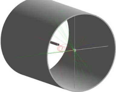
Within the simulation, the engine is designed so a solenoid forms the outer cylindircal shell of the engine and produces a non uniform magnetic field that becomes weaker closer to the exhaust. Solenoids can produce non uniform magnetic fields in various ways; for example, by varying the radius which would give the solenoid a conical shape or by maintaining a cylindrical shape but vary-ing the number of turns per length or current that flows through the solenoid. For this simuation, the latter option is chosen in order to give the particles the most room to propagate through the magnetic field and be redirected. The sole-noid is placed in a Cartesian coordinate system so that the radius of the solesole-noid extends in the x and y directions while the length of the solenoid runs along the z-axis. Furthermore, the solenoid is given realistic material properties within the simulation in order to interact with particles that may come in contact with or pass through the solenoid and potentially produce additional annihilations. The solenoid is given a 10 cm thickness as well as niobium-titanium alloy material, a common material used in the particle physics industry to produce solenoids with strong magnetic fields [4].
The non-uniform magnetic field model produced by the solenoid follows [2], where the field has both radial and axial components given by
( )
max(
1)
z
B z =B −gz and
( )
1 max2
r
B r = B r, where g is a gradient parameter that
determines how quickly the field strength varies along the z-axis. For this study, we construct the gradient term to produce a linear decline in the magnetic field from the forward-end to the exhaust.
Within the solenoid, a liquid hydrogen target is positioned along the z-axis, which corresponds to the longitudal axis of the solenoid. The liquid hydrogen is encased in 1 mm thick stainless steel, grade 301, in order to simulate a realistic scenario in which the incoming antiproton beam would need to pass through a container to reach the liquid hydrogen target. At the forward end of the engine, an antiproton (p) beam is simulated with a gaussian width of σx=σy=1 mm.
DOI: 10.4236/jmp.2019.1011089 1356 Journal of Modern Physics Figure 1. An isometric view of the basic core design.
The simulation allows for control over several parameters which are used for optimization as given by Table 1. These are the same parameters explored by Keane and Zhang for engine optimization though the ranges for optimization differ slightly. We scan these parameters with the updated analysis structure and engine geometry in an attempt to reproduce the results of Keane and Zhang’s simulation. The optimization is performed by varying a single parameter using the ranges and step sizes given by Table 1 while all other parameters are held constant. For each parameter set, 100,000 events are generated where an event corresponds to an antiproton fired at the liquid hydrogen target. Data is ga-thered on a particle by particle basis and is analyzed in an ntuple structure with-in ROOT [5]. Once each parameter is optimized, an additional 100,000 events are generated with each parameter set to its optimized value.
3. Results
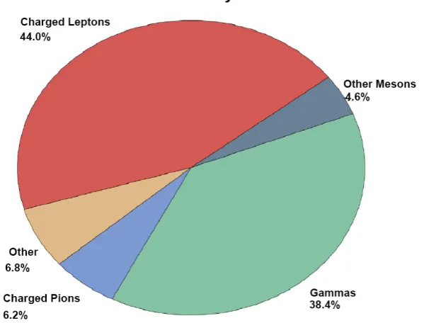
The simulation produces a myriad of various daughter particles as shown in Figure 2. The most abundant particles are gammas and charged leptons. Since gammas are electrically neutral, they cannot be redirected by the magnetic field and therefore make a negligible contribution to the impulse imparted to the en-gine. These gammas do pose a significant concern in terms of radiation which can be solved with significant radiation shielding, though extensive considera-tion of gamma radiaconsidera-tion is beyond the scope of this paper. Addiconsidera-tionally, charged leptons prove to be very inefficient in being redirected through the exhaust as only ≈ 8% of charged leptons produced make it to the exhaust. The next most abundant particles are charged pions which have a significant number of par-ticles reaching the exhaust compared to the number produced. For this reason, this analysis focuses on charged pions as these particles are the most abundant particles found at the exhaust.
We define the engine efficiency for each particle type by the ratio of the num-ber of particles reaching the exhaust plane to the numnum-ber created by the p annihilation, #exhaust
#production
=
DOI: 10.4236/jmp.2019.1011089 1357 Journal of Modern Physics Table 1. Summary of parameters explored for engine optimization.
Parameter Max Value Min Value Step Size
p KE 30 MeV 1 MeV 1 MeV
max
B 20 T 0 T 0.5 T
min
B 0 T 1 T 0.1 T
Solenoid Length 5 m 1 m 0.25 m
Solenoid Radius 2.5 m 0.5 m 0.25 m
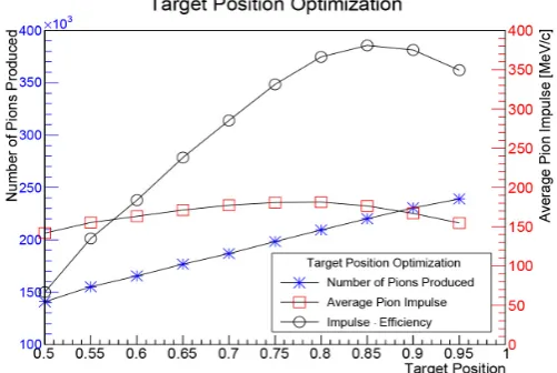
Target Position (percentage of total length) 95% 50% 5%
Figure 2. Shows the breakdown of the type of particles produced by the annihilation.
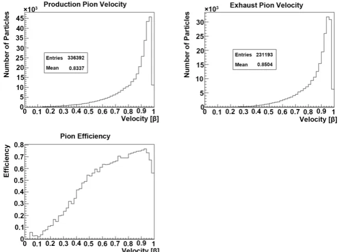
efficiency dependence on charged pion speed. After seeing this dependence, questions are raised as to what the proper efficiency number should be, specifi-cally [2] quotes an efficiency of nearly 80%, however this appears to be the effi-ciency for the most probable π± speed, not an average, which is indicated by
their nomenclature. Therefore, we quote two efficiencies, an average calculated from =
( )
β and max found at the most probable pion speed (≈ 0.95c). We define most probable pion speed as the speed at which most pions are travel-ling at the point of production.We calculate the impulse from the standard definition of I= ∆p. Specifically we calculate the z-component of the impulse on a particle per particle per event basis, therefore, for the ith particle in an event, the z-component of the impulse
is given by, .
, exhaust, prod, z i z i z i
I = p −p . It is the z-component of the impulse that
[image:5.595.225.525.236.464.2]DOI: 10.4236/jmp.2019.1011089 1358 Journal of Modern Physics Figure 3. Figure shows the speed distributions for charged pions at production and at the exhaust plane as well as their efficiency as a function of their production speed,
( )
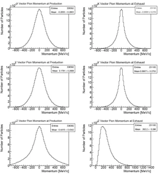
β .average close to zero indicating a negligible change in momentum in the x and y directions, as expected.
In calculating the impulse imparted on the engine we can calculate a specific impulse for the antiproton-proton annihilation, thus giving a value which we can compare to other fuel sources. Specific impulse is determined by the equation
equation z
sp I
I mg
= where Iz is the effective impulse, and m is the mass of the
reactants, a proton and p.
Our optimization is based on the product of average impulse and average effi-ciency, Iz⋅, generated by 100,000 events per parameter setting as previously shown in Table 1. The parameter is optimized when Iz⋅ is maximized indi-cating that the optimal balance of impulse and particles carrying the momentum through the exhaust has been achieved. Final optimized values of the parameters are given by Table 2. Furthermore, the variances in , Iz, and Iz⋅ for each parameter can be seen in Figures 5-10.
In its optimized state, the engine produces an impulse of 182.6 ± 0.5 MeV/c per event for charged pions which corresponds to (9.78 ± 0.03) × 10−20 Ns in SI
units and a specific impulse of (2.49 ± 0.08) × 106 s. This specific impulse is
DOI: 10.4236/jmp.2019.1011089 1359 Journal of Modern Physics Figure 4. Figure shows the components of charged pion momentum at production and at the exhaust plane.
Table 2. Value of optimized engine parameters.
Parameter Optimized Value
p KE 23 MeV
max
B 18.0 T
min
B 0.5 T
Solenoid Length 2.25 m
Solenoid Radius 2.25 m
Target Position (percentage of total length) 85 %
4. Conclusions
This simulation has shown that antimatter has exceedingly great potential as a fuel source for interstellar travel. The high specific impulse of (2.49 ± 0.08) × 106
[image:7.595.209.539.492.616.2]DOI: 10.4236/jmp.2019.1011089 1360 Journal of Modern Physics Figure 5. Figure shows the optimization for the kinetic energy of the
[image:8.595.247.501.307.490.2]incoming antiproton.
Figure 6. Figure shows the optimization of the Bmax parameter.
[image:8.595.250.501.535.704.2]DOI: 10.4236/jmp.2019.1011089 1361 Journal of Modern Physics Figure 8. Figure shows the optimization of the solenoid length
[image:9.595.248.503.294.463.2]pa-rameter.
Figure 9. Figure shows the optimization of the solenoid radius pa-rameter.
[image:9.595.249.500.513.681.2]DOI: 10.4236/jmp.2019.1011089 1362 Journal of Modern Physics Specific impulse as calculated here, however, merely indicates a maximum po-tential performance as the actual performance of the engine is limited by the rate at which fuel can be supplied to the reaction point.
The difficulty in utilizing antimatter in an engine as proposed here lies in the ability to produce enough antiprotons to fuel a spaceship. With current state of the art beam densities at 107 antiprotons/s [8], the engine would only produce a
thrust of 9.78 × 10⁻¹³ N. When this thrust is applied to a 500 ton spacecraft, the
resulting acceleration would be equal to 2.16 × 10⁻¹⁸ m/s2. At this rate it would
take 4.41 × 10²⁰ years to reach half the speed of light. If the beam density was
in-creased to 1028 antiprotons/s, the spacecraft would reach half the speed of light in
just 1.6 days. Current proton beam densities produced for experiments con-ducted at Fermilab can supply protons to a target at a rate as high as 9.6 × 10¹³
protons/s [9]. If enough antiprotons were produced to create comparable p beams, it would still take an extraordinarily long time to reach half the speed of light at 4.59 × 10¹¹ years. Chemical rockets, however, can supply fuel to the
reac-tion point at much higher rates, allowing for more reacreac-tions in a given period of time which results in a higher thrust. As a result, these rockets compensate for a lower specific impulse by a high mass flow rate whereas antimatter fuel is heavily restricted by the low rate at which antiprotons are supplied to the reaction point despite a high specific impulse.
Obviously, in order to construct a practical antimatter engine there is a need for much denser p beams, but in order to produce denser beams p produc-tion rates need to be improved. Frisbee offers a positive outlook on the increase in antimatter production stating that in 45 years, p production increased on the order of 106[1] and that it is not unreasonable to believe that a similar
in-crease in magnitude of production may occur in the following 45 years. Fur-thermore, the addition of multiple beams within a single engine would increase the rate at which antiprotons are delivered to the target; however, 10p beams would be needed just to increase the beam density by one order of magnitude.
Other issues in utilizing an antimatter fueled engine come from the naturally dangerous nature of antimatter due to its annihilation upon contact with ordi-nary matter. For this reason, use of an antimatter engine may only be feasible in outer space where an absence of atmosphere will allow antiprotons to propagate through the engine without being annihilated before reaching the desired anni-hilation point. The reaction of antimatter with matter also makes storing anti-protons difficult. Although storage of antianti-protons has been achieved for long pe-riods of time through magnetic suspension within a vacuum, there are greater challenges in being able to store enough antiprotons needed to fuel a space ship in a safe manner. Considering these factors, it is very unlikely that antimatter will ever completely replace chemical fuels but rather be used in conjunction with chemical rocket for deep space missions in the distant future.
DOI: 10.4236/jmp.2019.1011089 1363 Journal of Modern Physics maximize the effective exhaust velocity, we have optimized efficiency and im-pulse in order to maximize the imim-pulse imparted on the engine. We feel this is a more effective approach to optimizing the antimatter engine as impulse is re-sponsible for the thrust and acceleration of the engine whereas effective exhaust velocity is more useful in determining the maximum achievable velocity of the engine. As we have discussed previously, the difficulty in utilizing an antimatter engine lies in the ability to achieve a large enough acceleration to make a prac-tical antimatter engine.
Acknowledgements
Matthew Dubiel is grateful to have received a scholarship through the STEM Connections Program at Lewis University, which is supported in part by NSF S-STEM Award #1458353, and to have had the opportunity to participate in this research as a STEM Connections Scholar. Any opinions, findings, and conclu-sions or recommendations expressed in this material are those of the authors and do not necessarily reflect the views of the National Science Foundation. The authors would also like to thank the Lewis University Summer Undergraduate Research Experience (S.U.R.E.) for funding this work during one summer.
Conflicts of Interest
The authors declare no conflicts of interest regarding the publication of this pa-per.
References
[1] Frisbee, R.H. (2003) How to Build an Antimatter Rocket for Interstellar Mis-sions-Systems Level Considerations in Designing Advanced Propulsion Technology Vehicles. Impact of Interstellar Vehicle Acceleration and Cruise Velocity on Total Mission Mass and Trip Time.39th AIAAIASMEJSAWASEE Joint Propulsion Con-ference and Exhibit, Huntsville Alabama, 20-23 July 2003.
https://doi.org/10.2514/6.2003-4676
[2] Keane, R.L. and Zhang, W.M. (2011) Journal of Propulsion and Power, 27, 1153-1156.
[3] Allison, J., et al. (2016) Nuclear Instruments and Methods in Physics Research A, 835, 186-225.
[4] Ostojic, R., et al. (2014) IEEE Transactions on Applied Superconductivity, 24, 1-4. [5] Antcheva, I., et al. (2009) Computer Physics Communications, 180, 2499-2512. [6] Powell, J., Maise, G. and Paniagua, J. (2004) Aerospace America, 42, 36-38. [7] Borowski, S.K., et al. (2010) Nuclear Thermal Propulsion (NTPS). Wiley Online
Li-brary.
[8] FLAIR—Facility for Low-Energy Antiproton and Heavy Ion Research.
https://www.fair-center.eu/public/experiment-program/appa-physics/flair.html