© 2019, IRJET | Impact Factor value: 7.34 | ISO 9001:2008 Certified Journal
| Page 368
Comparative Study of Flat Slab and Conventional Slab Structure with
and without shear walls Using ETABS
Dr. K NARESH
Professor & HOD, Dept. of civil Engineering. SKIT Bengaluru, Karnataka, India.
---***---Abstract - In today’s construction activity the use of flat slabis quite common which enhances the weight reduction, speed up construction, and economical. Similarly from the beginning conventional slab has go it place in providing features like more stiffness, higher load carrying capacity, safe and economical also. As the advancement era began practice of flat slab becomes quite common. In the present dissertation work a G+14 commercial multistoried building having flat slab and conventional slab has been analyzed for the parameters like base shear, storey drift, Storey stiffness, and displacement. The performance and behavior of both the structures in seismic zones II & V of India has been studied.
Displacement of industrial and commercial structure constructed using flat slab system is more than the conventional slab system. Here we can say that flat slab with shear wall gives better displacement resisting. With the increase in height of structure displacement is also goes on increasing. It is seen that story drift is maximum for the conventional slab compared to flat slab and very less for the flat slab with shear wall. Story stiffness of conventional slab building is stiffer than Flat slab building. As the story no decreases stiffness goes on increasing.
Key Words: Flat slab, drop, conventional slab, Shear wall,
ETABS.
1. INTRODUCTION
From last two decades there is a high increase in the high rise buildings and modern trend is towards high rise structures. In tall buildings with increase in height lateral loads have prime consideration. From the effect of gravity resulting most common loads are dead load, live load and snow load. Buildings are also subjected to lateral loads caused by wind and earthquake. Due to the lateral loads develop high stresses, produce sway movement or vibrations.
Flat slab are used to avoid the beam-column clogging, and it is very economical. Flat slabs directly transfer the loads to columns without beams. But flat slabs are not efficient in transfer the lateral loads. Punching shear strength around the column-slab connections always possess a problem. Punching shear is a type of failure of reinforced concrete slabs subjected to high localized forces. When the total shear force exceeds the shear resistance of the slab, the slab will be pushed down around the column is termed as punching shear in flat slabs. This results in the column breaking through the portion of the surrounding slab. As a solution of
seismic load resistance, time and cost effective construction shear walls are most effective one method.
Flat plate construction is widely used in residential, office and industrial buildings in many parts of the world. The main advantage of this construction is the faster construction compared to mushroom and ribbed slabs. Generally, slabs are supported by beams and these beams are supported by columns. Beam reduces available net clear ceiling height. Sometimes beams are avoided and slabs are directly supported by columns. This type of construction provides aesthetical appearance also. Those slabs which are directly supported by columns are called as flat slabs. Flat slab also referred as beamless slab, it is the directly connected by columns without beams. Due to the advantages of flat slabs over other reinforced concrete floor system engineers are mostly used in construction works.
The main disadvantages of flat slab systems are; they are not suitable for supporting brittle (masonry) partitions, higher slab thickness, Chance for progressive collapse is more in flat slab due to the punching shear failure, in flat slabs, the middle strip deflection may be critical.
1.1 CONVENTIONAL BEAM SLAB SYSTEM
Conventional slab is a slab supported in all 4 edges by beams. The loads are transferred by the beams to the columns. Conventional slab system is generally used in residential buildings and in small construction. The main advantage of this conventional slab system is, we can design for a maximum span and maximum load by increasing the depth of the beams and cross section of the columns without any significant increase in the depth of the slab.
1.2 FLAT SLAB SYSTEM
A reinforced concrete flat slab, also called as beamless slab, is a slab supported directly by columns without beams. A part of the slab bounded on each of the four sides by center line of column is called panel. The thickened portion i.e. the projection below the slab is called drop or drop panel. Flat slab is mainly used in commercial buildings where the aesthetic view is more important and for the ease of the construction of formwork. Flat slab is a reinforced concrete slab supported directly by concrete columns without the use of beams. Flat slab is defined as one sided or two-sided support system with sheer load of the slab being concentrated on the supporting columns and a square slab called drop panels.
Figure: 2 Flat slab
1.3 Shear wall as a bracing method
Shear walls are the vertical elements to resist the horizontal force in s structure. Shear walls directly resist the lateral force along the length of the wall. By properly detailed longitudinal and transverse reinforcement can achieve the necessary strength to avoid the structural damage under earthquakes. Lateral forces are derived from winds and earthquakes that are applied horizontally to the building.
Figure: 3 Building with shear wall
2. LITERATURE REVIEW
Lan N Robertson (1997) [1] In this study the analysis of flat slab structures subjected to combined lateral and gravity loads. Using a three dimensional model, analysis of a flat slab building can have done when it subjected to vertical and lateral loads which includes both slab column frame elements and the lateral framing system (shear wall) if present. This study reviews two structural analysis models and compares them to experimental test results. A two-beam analytical model more accurately predicts the test results with respect to slab moment distribution and lateral drift. Three dimensional analysis done by ETABS computer program. These models assume a uniform slab effective width coefficient and constant cracking factor for an entire span. The analytical models were unable to reproduce the slab flexural moment distribution observed in test specimen at either 0.5 or 1.5 % drift levels. By replacing the single beam element with two-beam elements connected at the point of contra flexure, the difference between cracking in the positive and negative moment regions was incorporated in to the mode.
M A Rahman (2012) [2] He conducted a study on effect of openings in shear wall on seismic response of structures. In this paper, finite element modeling in analyzing and exploring the behaviour of shear wall with opening under seismic load actions, an attempt is made to apply the finite element modeling. A shear wall in a building contains many openings due to functional requirements such as doors, windows and other openings. This study is carried out using linear elastic analysis with the help of software ETABS under the earthquake loads in equivalent static analysis. This study reveals that, the size of the openings as well as their locations in shear walls, if will affect the stiffness as well as seismic responses of structure. If the area of openings more, the displacement increases with increasing storey level. Thickening wall around the door openings are more effective than that of window opening as far as displacements in concerned at top most storey level.
Lakshmi K O (2014) [4] In this journal find the effect of shear wall location in buildings subjected to seismic loads. A symmetric sixteen story residential building considered for the analysis. The finite element analysis software ETABS is used to create the 3-D model and run the analysis by pushover method. Eight different models were considered. Due to the seismic ground motion at the base of the structure base shear is maximum. Maximum reduction in displacement is obtained for frame with core and corner shear wall.
3. OBJECTIVES
1. To obtain the most effective structure to resist the lateral loads.
© 2019, IRJET | Impact Factor value: 7.34 | ISO 9001:2008 Certified Journal
| Page 370
3. Efficiency of concrete structures with and without shearwall with respect the story displacement, drift and Storey stiffness, overturning moment, time period.
4. The effect of shear wall on behavior of concrete structures are summarized using the obtained results, by concluding the variation of results in structures.
4. METHODOLOGY
Following methodology is adopted to analyses.
1. RC concrete structure is considered for the study having 15 stories of height 45 m each floors is considered as 3 m height.
2. The regular concrete moment resisting frame of square plan is considered as base or reference model.
3. With reference to base model, Flat slab model are studied and compared with shear wall for all the models for seismic.
4. In order to get consistent results, the floor height is kept constant for all structures.
5. To understand the behavior under lateral loads applied as per IS 1893: 2002 are used respectively.
6. Based on the results and responses from earthquake loads applied, conclusion are made.
5. PARAMETERS CONSIDERED FOR MODELLING
Table- 1 Preliminary Data for 15-story Conventional slab building.
SL.NO PARAMETERS
1 Length in X-direction 35m 2 Length in Y-direction 35m 3 Floor to floor height 3m
4 No of stories 15
5 Total height of the building 45m
6 Slab thickness 150mm
7 Grade of concrete M30
8 Grade of steel HYSD 415,500
9 Wall size 300mm
10 Column size 500mmX500mm
11 Beam size 300mmx600mm
12 Live load in Floors 2kN/m2 13 Live load in Terrace 1.5kN/m2
14 Floor finish 1.5kN/m2
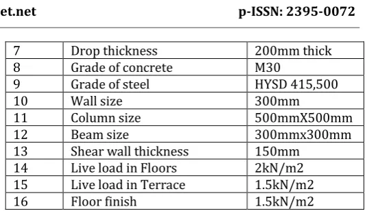
Table -2: Preliminary Data for 15-story Flat slab building.
SL.NO PARAMETERS
1 Length in X-direction 35m 2 Length in Y-direction 35m 3 Floor to floor height 3m
4 No of stories 15
5 Total height of the building 45m
6 Slab thickness 150mm
7 Drop thickness 200mm thick
8 Grade of concrete M30
9 Grade of steel HYSD 415,500
10 Wall size 300mm
11 Column size 500mmX500mm
12 Beam size 300mmx300mm
13 Shear wall thickness 150mm 14 Live load in Floors 2kN/m2 15 Live load in Terrace 1.5kN/m2
[image:3.595.299.567.63.217.2]16 Floor finish 1.5kN/m2
Table -3: PreliminaryData for Seismic Load Parameters
SL.No Seismic load parameters Zone 2-5
1 Zone factor 0.16-.36
2 Response reduction factor 5
3 Importance factor 1.5
4 Type of soil strata 2(Medium)
[image:3.595.304.563.241.542.2]5 Damping 5%
Table -4: Load Combinations
Type Design Load Combinations Gravity analysis 1.5 (Dead Load + Live Load) Equivalent Static
Analysis 1.2 (Dead Load + Live Load + EQX) 1.2 (Dead Load + Live Load - EQX)
1.2 (Dead Load + Live Load + EQY) 1.2 (Dead Load + Live Load - EQY) 1.5 (Dead Load + EQX)
1.5 (Dead Load - EQX) 1.5 (Dead Load + EQY) 1.5 (Dead Load - EQY) 0.9 (Dead Load + EQX) 0.9 (Dead Load - EQX) 0.9 (Dead Load + EQY) 0.9 (Dead Load - EQY)
6. Models considered.
Figure: 5 Plan and elevation view of conventional slab
Structure.
Figure: 6 Flat slab structure without shear wall.
Figure: 7 Rendered view of flat slab structure
Figure: 8 Flat slab structure with shear wall.
Figure: 9 Rendered view of flat slab with shear wall structure.
7. RESULTS AND DISCUSSION
DISPLACEMENT: It is total displacement of ith storey with respect to ground and there is maximum permissible limit prescribed in IS codes for buildings.
Table; 4 Story Displacement for ZONE-II
STOREY DISPLACEMENT ALONG EQX
STOREY CS WO SW FS WO SW FS W SW
15 9.936 98.48 32.542
14 9.716 91.454 29.248
13 9.363 83.869 25.973
12 8.888 75.804 22.743
11 8.309 67.347 19.583
10 7.644 58.595 16.526
9 6.91 49.656 13.605
8 6.121 40.662 10.855
7 5.29 31.776 8.317
6 4.429 23.215 6.031
5 3.55 15.283 4.041
4 2.66 8.421 2.39
3 1.768 3.284 1.128
2 0.893 0.847 0.387
1 0.134 0.182 0.088
© 2019, IRJET | Impact Factor value: 7.34 | ISO 9001:2008 Certified Journal
| Page 372
Chart-1Plot storey v/s displacement for structurealong EQX.
Table; 5 Story Displacement for ZONE-III
STOREY DISPLACEMENT ALONG EQX
STOREY CS WO SW FS WO SW FS W SW
15 19.124 15.01 52.067
14 18.003 14.254 46.796
13 16.802 13.434 41.557
12 15.534 12.558 36.388
11 14.211 11.635 31.333
10 12.844 10.673 26.442
9 11.444 9.68 21.768
8 10.02 8.661 17.369
7 8.58 7.621 13.307
6 7.132 6.567 9.649
5 5.684 5.502 6.465
4 4.241 4.43 3.824
3 2.81 3.35 1.805
2 1.416 2.226 0.619
1 0.213 0.544 0.141
0 0 0 0
Chart-2Plot storey v/s displacement for structure along EQX.
Table; 6 Story Displacement for ZONE-IV
STOREY DISPLACEMENT ALONG EQX
STOREY CS WO SW FS WO SW FS W SW
15 19.124 15.01 52.067
14 18.003 14.254 46.796
13 16.802 13.434 41.557
12 15.534 12.558 36.388
11 14.211 11.635 31.333
10 12.844 10.673 26.442
9 11.444 9.68 21.768
8 10.02 8.661 17.369
7 8.58 7.621 13.307
6 7.132 6.567 9.649
5 5.684 5.502 6.465
4 4.241 4.43 3.824
3 2.81 3.35 1.805
2 1.416 2.226 0.619
1 0.213 0.544 0.141
0 0 0 0
Chart-3Plot storey vs displacement for structure along EQX.
Table; 7 Story Displacement for ZONE-V
STOREY DISPLACEMENT ALONG EQX
STOREY CS WO SW FS WO SW FS W SW
15 43.03 354.528 117.15
14 40.506 329.235 105.291
13 37.804 301.927 93.504
12 34.951 272.894 81.873
11 31.975 242.449 70.5
10 28.9 210.941 59.494
9 25.749 178.762 48.977
8 22.545 146.383 39.079
7 19.305 114.393 29.941
6 16.048 83.572 21.71
5 12.789 55.018 14.547
4 9.542 30.316 8.603
3 6.324 11.823 4.062
2 3.186 3.048 1.392
1 0.478 0.657 0.317
Chart-4Plot storey vs displacement for structure along EQX.
Story Drift
It is defined as ratio of displacement of two consecutive floor to height of that floor. It is very important term used for research purpose in earthquake engineering.
Table; 8 Story Drift for Zone-II
STOREY DRIFT ALONG EQX
STOREY CS WO SW FS WO SW FS W SW 15 7.30E-05 0.002342 0.001098 14 0.000118 0.002528 0.001091 13 0.000158 0.002688 0.001077 12 0.000193 0.002819 0.001053 11 0.000222 0.002917 0.001019 10 0.000245 0.002979 0.000974 9 0.000263 0.002998 0.000917 8 0.000277 0.002963 0.000846 7 0.000287 0.002854 0.000762 6 0.000293 0.002645 0.000664 5 0.000297 0.002289 0.000551 4 0.000297 0.001714 0.000429 3 0.000292 0.000812 0.000247 2 0.000253 0.000222 0.000104 1 8.90E-05 0.000122 5.90E-05
0 0 0 0
Chart-5 Plot storey vs drift for structures along EQX.
Table; 9 Story Drift for Zone-V
STOREY DRIFT ALONG EQX
STOREY CS WO SW FS WO SW FS W SW 15 0.000841 0.008431 0.003953 14 0.000901 0.009103 0.003929 13 0.000951 0.009678 0.003877 12 0.000992 0.010148 0.003791 11 0.001025 0.010503 0.003669 10 0.00105 0.010726 0.003506 9 0.001068 0.010794 0.003299
8 0.00108 0.010665 0.003047
7 0.001086 0.010275 0.002744 6 0.001086 0.009521 0.002389 5 0.001082 0.008239 0.001984 4 0.001073 0.006171 0.001543 3 0.001046 0.002925 0.00089 2 0.000903 0.000798 0.000374 1 0.000319 0.000438 0.000211
0 0 0 0
Chart-6 Plot storey vs drift for structures along EQX.
STOREY STIFFNESS
Story Stiffness is the ratio of story force to average drift experienced by each storey. And also Conventional slab and Flat slab is compared for this parameter. If structures are stiff then it’s suitable for long period of sites
Table; 10 Storey stiffness for ZONE-II
STOREY STIFFNESS IN KN/m
© 2019, IRJET | Impact Factor value: 7.34 | ISO 9001:2008 Certified Journal
| Page 374
5 1265141.553 94916.052 407702.6634 1281725.181 128199.71 531030.038 3 1317120.084 283184.527 970218.788 2 1527475.333 980182.376 2203306.44 1 8658652.253 3580337.215 8230752.54
0 0 0 0
Chart-7Plot storey vs storey stiffness for structures along EQX.
Table; 11 Storey stiffness for ZONE-V
STOREY STIFFNESS IN KN/m
STOREY CS WO SW FS WO SW FS W SW 15 1149667.302 64872.816 143068.64 14 1164747.97 65227.945 156228.65 13 1177445.783 65499.248 169044.64 12 1188669.727 65819.097 182146.88 11 1199051.157 66306.619 196253.48 10 1209058.143 67106.466 212275.16 9 1219060.686 68436.216 231473.25 8 1229370.225 70658.961 255757.71 7 1240266.267 74466.805 288323.86 6 1252036.24 81318.023 335061.32 5 1265141.553 94916.052 407702.66 4 1281725.181 128199.71 531030.04 3 1317120.084 283184.527 970218.79 2 1527475.333 980182.376 2203306.5 1 8658652.253 3580337.215 8230752.5
0 0 0 0
Chart-8Plot storey vs storey stiffness for structures along EQX.
NATURAL TIME PERIOD
A time period is the time needed for one complete cycle of vibration to pass a given point.
Table; 12Time period for ZONE-II
TIME PERIOD IN (Sec)
STOREY CS WO SW FS WO SW FS W SW
1 2.301 8.589 5.042
2 2.301 8.589 5.042
3 2.063 5.318 3.048
4 0.758 2.626 1.084
5 0.758 2.626 1.084
6 0.684 1.703 0.666
7 0.441 1.369 0.439
8 0.441 1.369 0.439
9 0.404 0.952 0.272
10 0.311 0.838 0.251
11 0.311 0.838 0.251
12 0.285 0.623 0.173
8. CONCLUSIONS
Displacement of industrial and commercial structure constructed using flat slab system is more than the conventional slab system. Here we can say that flat slab with shear wall gives better displacement resisting.
With the increase in height of structure displacement is also goes on increasing.
Story shear of Flat slab building is less than conventional slab building in Y-direction.
Story shear is maximum at base level and it decreases as height of structure increases.
Base shear of flat slab building is less than the base shear in conventional slab building in both X and Y directions
It is seen that story drift is maximum for the conventional slab compared to flat slab and very less for the flat slab with shear wall.
Story stiffness of conventional slab building is stiffer than Flat slab building. As the story no decreases stiffness goes on increasing.
REFERENCES
[1] Lan N Robertson (1997), “Analysis of flat slab structures
subjected to combined lateral and gravity loads”, ACI Structural Journal, November-December 1997
[2] IS 1893 (part 1) (2002)” Indian Standard Criteria for
Practice for Earthquake Resistant Design of Structures General Provisions and Buildings (Fifth Revision)”. [3] M A Rahman (2012), “Effects of openings in shear wall on seismic response of structures”, International Journal of Computer Applications’, Volume 59, December 2012.
[3] Navyashree K (2014), “Use of flat slabs in multi-storey
commercial building situated in high seismic zone’, International Journal of Research in Engineering and Technology, Volume 03, August 2014.
[4] Lakshmi K O (2014), “Effect of shear wall location in
buildings subjected to seismic loads”, ISOI Journal Engineering and Computer Science, Volume 01, December 2014.
[5] Sachin P Dyavappanavar (2015), “Seismic analysis of RC
multi-storied structures with shear walls at different locations”, International Research Journal of Engineering and Technology, Volume 02, Aug-2015.
[6] K. G. Patwari (2016), “Comparative study of rc flat slab &
shear wall with conventional framed structure in high rise building”, International Journal of Engineering Research, Volume 05, February 2016.
[7] D. Kornack and P. Rakic, “Cell Proliferation without
Neurogenesis in Adult Primate Neocortex,” Science, vol.
294, Dec. 2001, pp. 2127-2130,
doi:10.1126/science.1065467.
[8] M. Young, The Technical Writer’s Handbook. Mill Valley,
CA: University Science, 1989.
[9] R. Nicole, “Title of paper with only first word
capitalized,” J. Name Stand. Abbrev., in press.