24
Modelling and Simulation of Automatic Voltage
Regulator System
Modu M. Ibrahim
Postgraduate Student
Elect/Elect Engineering Dept
University of Maiduguri
Jibril D. Jiya
Professor
Department of Mechatronics.
Abubakar Tafawabalewa
University
Idakwo O. Harrison
Department of Engineering
University of Maiduguri
Teaching Hospital
ABSTRACT
For obtaining efficient stability and good regulation of different devices in power system and industrial applications, automatic voltage regulators (AVR) are increasingly used. However, AVR without any controller will provides slow responses due to disturbance and may cause instability. In this study therefore, the objective is to consider a generator AVR system without PID controller and with PID controller, where the PID controller was tuned with a view for improving the response of the system and make comparison between the frequency deviation step response and the tuned PID controller block performance using linear block model and control techniques in MATLAB / Simulink environment, in which the design configuration and automated PID turning was used to tuned the PID controller for AVR system without and with PID controller for generator 1 and generator 2 respectively. Simulation results indicates that generator 1 shows higher frequency overshoot and oscillation as compared to generator 2, which shows low frequency overshoot and minimum oscillation. The performance response of the tuned AVR system in generator 2 with PID controller gives satisfactory settling time which was recorded at 1.44 second as against 5.54 second.
General Terms
Voltage Stability
Keywords
AVR, PID
1.
INTRODUCTION
The automatic voltage regulator (AVR) is widely used in electric power systems and industrial applications to obtain the stability and good regulation of different apparatus. It may be use as an electromechanical mechanism, passive or active electronic components. Depending on the design, it may be use to regulate AC or DC voltage [1]. Thus, maintaining constant voltage at the output terminal of a generator is essential for satisfactory mains power supply. The terminal voltage can be affected by disturbances, such, as change in load, temperature, speed e.t.c, such that voltage regulating equipment is required to keep the voltage constant and maintain continuous supply within acceptable quality. To achieve this, automatic voltage regulator (AVR) system is used in power generation site to ensure voltage stability at the generator terminal. However, AVR system without any controller will provide slow responses and may cause instability. Thus, need to provide proper control of generator by AVR system to ensure generators operated at safe and stable conditions for normal operations and fast response under different type of disturbance is very essential.
Nevertheless, AVR cannot respond to change in generator output voltage quickly due to the resultant oscillation when it subjected to disturbances, thus the AVR cannot effectively regulate steady state error. Thus, to improve the dynamic response as well as to reduce the steady state error in the AVR loop, a linear PID controller is used in this paper in order to study the responsiveness of the controller, the degree to which the controller overshoots the set point and the degree of system oscillation.
According to [2] AVR system usually consists of an amplifier, exciter, generator and a sensor. Exciter, which is the source of electrical power for field winding of a generator controlled by the AVR, is very effective during steady – state operation. But
The work by [3] observed that in case of sudden disturbances it may have negative influence on the damping of power swing. This may be reduced or eliminated by introduction of a supplementary linear controller, the PID controller which will be able to produce additional signal into the AVR control loop and in that way compensates voltage oscillations. In mid 1930s three mode controllers with proportional, integral and derivative (PID) actions were commercially available and gained widespread acceptance. And recently different linear control algorithms have been developed so far. However, the PID – type controller is still the most widely used control strategy in practice and 90% of all the industrial controllers are of the PID – type. This is as a result of its simplicity in design, adequate tuning capabilities and good performance [4].
Control of AVR system has been proposed in [5]. The authors designed an AVR system using MATLAB/Simulink and the performance of the system was evaluated using PID controller. It was deduced that the proportional controller (Kp) have the effect of reducing rise time, the integral controller (Ki) have the effect of eliminating steady - state error, and the derivative controller (Kd) have the effect of increasing stability of the system. In this work, the combined action of the three controllers will be tested as a single controller to determine their resultant effect instead of using them separately in the AVR system.
The work by [6] presented the development of excitation system in simulation environment. The excitation system and single machine modes are implemented using MATLAB/Simulink. The author provides some advices in parameter estimation of excitation system and highlights that transfer function model will be more useful in power system studies.
25 two cases will be considered, an ideal AVR system without
PID controller and AVR system with PID controller for generator system 1 and 2 respectively. Where the PID controller will be tuned with a view for improving the response of the system and make comparison between the frequency deviation step responses of the AVR and the tuned PID controller’s block performances. The objective is to consider a generator AVR system and find its steady state frequency deviation step and terminal voltage step response using linear control technique called PID controller using MATLAB/ simulink.
2.
CONCEPT OF AUTOMATIC
VOLTAGE REGULATOR (AVR)
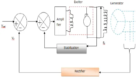
[image:2.595.315.564.79.278.2]AVR functions when there is voltage error occurrence between terminal voltage and reference voltage as a result of any disturbance in power system network. The regulation element is commanded up to a point to produce a higher output voltage by dropping less of the input voltage; if the output voltage is too high, the regulation element will normally be commanded to produce a lower voltage. A schematic of an AVR system is shown in figure 1. The voltage magnitude is sensed through the potential transformer on one phase. This voltage is rectified and compared to DC set point signal. The amplifier error signal controls the exciter field and increases the exciter terminal voltage. Thus, the generator field current is increased, which result in an increase in generated e.m.f. The reactive power generation is increased to a new equilibrium, raising the terminal voltage to desired value [7].
Figure 1: Systematic AVR System
Figure 2 describes the transfer function model of an AVR system. The generator terminal voltage 𝑉𝑡 is compared with a voltage reference 𝑉𝑟𝑒𝑓 to obtain a voltage error signal ΔV. This signal is applied to the voltage regulator shown as a block with transfer function 𝐾𝐴 1 + 𝑇𝐴𝑠 . The output of the regulator is then applied to exciter with a block of transfer
function 𝐾𝑒
1+𝑇𝑒𝑠 . The output of the exciter is then applied to
the field winding which adjusts the generator terminal voltage. The generator field can be represented by a block with a transfer function
𝐾𝐹 1 + 𝑆𝑇𝑓 .
The total transfer function is given
𝛥𝑉
𝛥𝑉𝑟𝑒𝑓
=
𝐺 𝑆
1+ 𝐺 𝑆
(1)
Where, 𝐺 𝑆 =
𝐾𝐴 𝐾 𝑒 𝐾𝑓
1+ 𝑆𝑇𝐴 1+ 𝑆𝑇𝑒 1+ 𝑆𝑇𝑓 (2)
Figure 2: Block Diagram Representation of AVR System
Source: (elaerning.Vtu.in)
[image:2.595.318.553.375.454.2]3.
MODELLING OF THE AVR SYSTEM
Figure 3.1 shows the basic components of an AVR system. It consists of a comparator, amplifier, exciter and generator [8].
Figure 3.1: Block Diagram of an AVR System
It is to be noted that error voltage 𝑒 = 𝑉 𝑟𝑒𝑓 − 𝑉 (3) Assume that for some reason the terminal voltage of the main generator decreases. This will result in decrease in 𝑉 . this will immediately results in an increased “error voltage” 𝑒
which in turn, causes increased value of 𝑉𝑅, 𝑖𝑒,𝑉𝑓, and 𝑖𝑓. With increase in 𝑖𝑓, the generator field flux also increases. Thus, raising the magnitude of the internal generator e.m.f and hence the terminal voltage.
For the comparator,
∆ 𝑉
𝑟𝑒𝑓 −∆ 𝑉 = ∆𝑒
(4)Taking the Laplace transform of equation (2) gives;
∆ 𝑉 𝑟𝑒𝑓 𝑆 − ∆ 𝑉 𝑆 = ∆𝑒 𝑆 (5)
For the amplifier, ∆𝑉𝑅 = 𝐾𝐴∆𝑒 (6) Where 𝐾𝐴 is the amplifier gain Laplace transform of equation (4) yields;
[image:2.595.57.279.429.558.2]26 This equation implies instantaneous amplifier response. But in
reality, the amplifier will have a time delay that can be represented by a time constant 𝑇𝐴.
Then, ∆𝑉𝑅 𝑆 and ∆𝑒 𝑆 are related as
∆𝑉𝑅 𝑆 = 𝐾𝐴
1 +𝑠𝑇𝐴∆𝑒 𝑆
(8)
Here, 𝑲𝑨
𝟏 +𝒔𝑻𝑨 is the transfer function of the
amplifier 𝐺𝐴 𝑆 .
For the exciter field, if 𝑅𝑒 and 𝐿𝑒 represent respectively the resistance and inductance of the exciter field, then
𝑉𝑅 = 𝑅𝑒𝑖𝑒 + 𝐿𝑒𝑑𝑡𝑑𝑖𝑒 and hence
∆𝑉𝑅 = 𝑅𝑒∆𝑖𝑒+ 𝐿𝑒 𝑑
𝑑𝑡 ∆𝑖𝑒 (9) The exciter field current 𝑖𝑒 produces voltage 𝑉𝑓, which is the rectified armature voltage of the excitation. Then
∆𝑉𝑓 = 𝐾1∆𝑖𝑒 (10) Where 𝐾1 is the rectified armature volt per ampere of exciter field current.
Taking Laplace transformation of the above two equations (9) and (10) and eliminating ∆𝑖𝑒 𝑆 , we get
∆𝑉𝑓 𝑆 = 𝐾𝑒
1 +𝑆𝑇𝑒∆𝑉𝑅 𝑆 (11)
Where 𝐾𝑒= 𝐾1
𝑅𝑒 and 𝑇𝑒 =
𝐿𝑒
𝑅𝑒 (12)
Thus the transfer function of the exciter, 𝑮𝒆 𝑺 = 𝟏 +𝑺𝑻𝑲𝒆
𝒆
The Generator field considering the field of a synchronous generator, using KVL;
∆𝑉𝑓 = 𝑅𝑓∆𝑖𝑓+ 𝐿𝑓𝑓 𝑑
𝑑𝑡 ∆𝑖𝑓 (13)
Taking Laplace transform;
∆𝑉𝑓 𝑆 = 𝑅𝑓+ 𝑠𝐿𝑓𝑓 ∆𝑖𝑓 𝑆 (14)
In the generator, internal emf and the field current are related as;
E =
𝜔 𝐿𝑓𝑎 𝑖𝑓2 (15)
Where 𝐿𝑓𝑎 is the mutual inductance coefficient between rotor field and stator armature. Thus;
∆𝑖
𝑓=
𝜔 𝐿 2𝑓𝑎
∆
E
(16)Laplace transform of equation (16) gives
∆𝑖
𝑓𝑆
=
𝜔 𝐿 2𝑓𝑎
∆
E
𝑆
(17)
Substituting equation (14), gives
∆𝑉
𝑓𝑆
=
𝜔 𝐿 2𝑓𝑎
𝑅
𝑓+ 𝑠
𝐿𝑓𝑓
∆
E
𝑆
Thus,
∆
E
𝑆
=
𝜔 𝐿𝑓𝑎2 1 𝑅𝑓 + 𝑠𝐿𝑓𝑓
∆𝑉
𝑓𝑆
(18)
From the above equation, the field voltage transfer ratio can be written as
∆E 𝑆 ∆𝑉𝑓 𝑆
≈
∆ 𝑉 𝑆
∆𝑉𝑓 𝑆
=
𝜔 𝐿𝑓𝑎2 1 𝑅𝑓+ 𝑠𝐿𝑓𝑓
=
1+ 𝑆𝐾𝑓𝑇𝑓
(19)
Thus, the transfer function of the generator field is 𝐾𝑓
1+𝑆𝑇𝐺
Where,
𝐾
𝑓=
𝜔 𝐿𝑓𝑎2 𝑅𝑓
and
𝑇
𝐺=
𝐿𝑓𝑓
𝑅𝑓
(20)
3.1
Simulink Model of AVR
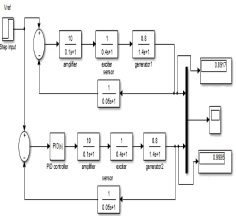
Figure 3.2 shows an AVR system model in MATLAB simulink environment, where a combined simulation block model was constructed for the three (3) cases in other to obtain their respective step response.
The design configuration and automated PID turning tool of MATLAB was used to tune the PID controller for AVR. The PID controller is tuned to achieve better control action by further minimizing the error. This was performed by using MATLAB function “pidtune” (PID turning algorithm) for linear model and launching the PID tuner, using pidtool command. Upon launching the PID tuner the close loop step response of the system is obtained by automatically turning the gain constants KI, KP and KD.
The Parameters of the AVR and PID used for the simulation is shown in table 3.1 and table 3.2. The parameters were obtained in [9].
Table 3.1: AVR Parameter
Quality Transfer Function Gain Time Constant
Amplifier KA / ( 1 + TAS ) KA = 10 TAS = 0.1
Exciter KE / ( 1 + TEs ) KE = 1 TEs = 0.4
Generator Kc / ( 1 + TGs ) KG = 0.8 TGs = 1.4
Sensor KR / (1 + TRs ) KR = 1 TRs = 0.05
Table 3.2: PID Controller Parameter
Quality Gain
PID Controller Kp = 1.0
KI = 0.25
27
Figure 3.2 Generators with AVR and AVR with PID Controller
4.
SIMULATION RESULTS AND
DISCUSSION
[image:4.595.321.547.149.362.2]Simulink model block was simulated and a plot for frequency deviation step response were obtained in Figure 4.1 for the generator AVR system. The AVR was simulated with and without PID controller, it was observed that generator 1 shows high frequeny overshoot and oscillation than the generator 2, with PID controller which shows low frequency and minimum oscilation.
Figure 4.1 frequency deviation step response for the Generator System 1 and 2.
Figure 4.2 depicts the simulation result of the AVR response and the tuned PID controller response. The PID controller was tuned to further improve on the performance of the AVR loop. It can be seen from the plot that while using the tune PID controller the overshoot obtained is less as compared to
the case when the PID controller was not tuned. Table 4.1 presents the performance of the tuned response of the AVR system with PID controller. The settling time of the AVR with PID controller is less, which is recorded at 1.44 S as
against 5.54 S for the AVR without PID.
[image:4.595.320.543.423.538.2]Figure 4.2 Voltage step response for AVR systems with tuned PID controller
Table 4.3 Performance metrics of tuned AVR loop
5.
CONCLUSION
The reliability of generating system is determined by its ability for maintaining voltage and frequency within permissible limit. A generator was modeled to determine its terminal voltage step response, where the system was simulated considering two different configuration. It can be concluded that the generating system with PID controller shows satisfactory performance. It is found that turning of PID controller improves performance of systems. The settling time and rise time of the response acquired by the AVR system with tune PID controller is found to be less as compared to response acquired by the AVR system without PID controller.
[image:4.595.55.282.457.676.2]28
6.
REFERENCES
[1] Verma T & Mishra A. K (2014) "Comparative study of PID and FOPID Controller Response for Automatic Voltage Regulation" IOSR journal of Engineering (IOSRJEN) Vol 4, 1ssue 9 PP. 41 – 48.
[2] Patonding H. E, Lobo E. T and Sau M (2015) “Modeling Control of Automatic Voltage Regulator with Proportional Integral Derivative” International journal of research in Engineering and Technology. Vol.4, issue 9, PP 241 – 244.
[3] Vedrana J. Kresimir M and Zeijko S (2013) “Excitation System Models of Synchronous Generator” Faculty of
[4] Lodh B (2014) “Simulink Based Model for Analyzing the Ziegler – Nichols Turning Algorithm as Applied on Speed Control of DC Motor International Journal of Advanced Research in Electrical, Electronics and Instrumentation Engineering. Vol 3, issue 1, PP 6641 – 6645.
[5] Mathur P and Joshi S.K (2015) “PID turning of Automatic Voltage Regulator” international Journal of Research and Analytical Reviews. Vol 2, Issue 3 PP 18 – 21.
[6] Lai J (2007) “Parameter Estimation of Excitation System” Master Thesis, Electrical and Computer Engineering, Graduate Faculty of North Carolina, Raleigh, North Carolina. PP 15 – 17
[7] Dabur P, Yadav N. K & Tayal V. K (2011) "Matlab Design and simulation of AGC and AVR for multi Area system and Demand Side Management" international journal of computer and Electrical Engineering Vol 3, No:2, PP 259 – 264.
[8] Tony F. T and Prakash R (2014) "Load frequency Control of a two Area Hybrid System Consisting of a Grid Connected PV system and thermal Generator" International Journal of Research in Engineering and Technology Vol: 3, issue 7, PP. 573-580.