Cracking Android Pattern Lock in Five Attempts
Guixin Ye
†, Zhanyong Tang
∗,†, Dingyi Fang
†, Xiaojiang Chen
†, Kwang In Kim
‡, Ben Taylor
§, and Zheng Wang
∗,§†School of Information Science and Technology, Northwest University, China
Email: [email protected],{zytang, dyf, xjchen}@nwu.edu.cn ‡Department of Computer Science, University of Bath, UK
Email: [email protected]
§School of Computing and Communications, Lancaster University, UK
Email:{b.d.taylor, z.wang}@lancaster.ac.uk
Abstract—Pattern lock is widely used as a mechanism for authentication and authorization on Android devices. This paper presents a novel video-based attack to reconstruct Android lock patterns from video footage filmed using a mobile phone camera. Unlike prior attacks on pattern lock, our approach does not require the video to capture any content displayed on the screen. Instead, we employ a computer vision algorithm to track the fingertip movements to infer the pattern. Using the geometry information extracted from the tracked fingertip motions, our ap-proach is able to accurately identify a small number of (often one) candidate patterns to be tested by an adversary. We thoroughly evaluated our approach using 120 unique patterns collected from 215 independent users, by applying it to reconstruct patterns from video footage filmed using smartphone cameras. Experimental results show that our approach can break over 95% of the patterns in five attempts before the device is automatically locked by the Android operating system. We discovered that, in contrast to many people’s belief, complex patterns do not offer stronger protection under our attacking scenarios. This is demonstrated by the fact that we are able to break all but one complex patterns (with a 97.5% success rate) as opposed to 60% of the simple patterns in the first attempt. Since our threat model is common in day-to-day life, this paper calls for the community to revisit the risks of using Android pattern lock to protect sensitive information.
I. INTRODUCTION
Pattern lock is widely used on Android devices to protect sensitive information. It is preferred by some users over PIN-or text-based passwPIN-ords, as psychology studies show that the human brain remembers and recalls visual information better than numbers and letters [9]. According to a recent study, 40% of the Android users use patterns to protect their devices in-stead of a PIN [7]. Pattern lock is also used for authentication. For example,Alipay, the largest third-party online-payment platform, uses pattern lock for the login authentication. Given its pervasive usage, a security breach of the pattern lock could lead to serious consequences.
*Corresponding authors: Zhanyong Tang and Zheng Wang
Researchers have demonstrated a number of ways to crack Android pattern lock. Smudge attacks use the oily residues left on the screen to recover the pattern [1]. However, this approach relies on the persistence of the smudge which can be easily destroyed by subsequent on-screen activities after unlocking. In a recent study, Zhang et al. [34] shows that it is possible to infer a locking pattern by analyzing how the WiFi signal is affected by the finger motions when drawing the pattern. Their approach is restricted to a limit set of scenarios due two reasons: (1) the complex setup of the attacking environment and (2) the WiFi signal can be disrupted by any moving objects nearby or body movements.
Recently, video-based side-channel attacks are shown to be effective in reconstructing PIN- or text-based passwords. Some of the early work in this area rely on video footage filmed using a camera directly facing the screen or the keyboard [4, 16]. Latest work shows that this limit can be lifted by exploiting spatial-temporal dynamics of the hands during typing [23]. Despite the success of video-based attacks on PIN- and text-based passwords, no work so far has exploited video-text-based side-channels to crack pattern lock. To do so, the attack must address a number of new challenges. These include: How to map the user’s fingertip movements to a graphical structure consisting of continuous points instead of discrete keystrokes? How to transform the fingertip movements tracked from the camera’s perspective to the user’s view point to correctly reconstruct the pattern? How to cancel the camera shake effect that can significantly affect the performance of the attack? How to identify two overlapping line segments of a pattern? The size of the touch-screen or the pattern grid can vary from one device or one application to the other, how can the algorithm adapt to these changes? These new challenges make prior work video-based attacks inapplicable. To overcome these challenges requires creative solutions to be constructed in the new application context of pattern lock.
This paper presents a novel approach to crack Android pattern lock using video footage that captures the user’s fingertip motions when drawing the pattern. Unlike smudge attacks [1], our approach does not require the video footage or images to be captured by a camera directly faced the screen. Furthermore, the video can be filmed at a distance of 2 meters from the user in public places. Such a distance is less likely to raise suspicion compared to shoulder surfing [21] that requires a closer observation distance to have a clear sight of the content displayed on the screen. Our attack employs a computer vision algorithm to track the fingertip motions from the video. Using
Permission to freely reproduce all or part of this paper for noncommercial purposes is granted provided that copies bear this notice and the full citation on the first page. Reproduction for commercial purposes is strictly prohibited without the prior written consent of the Internet Society, the first-named author (for reproduction of an entire paper only), and the author’s employer if the paper was prepared within the scope of employment.
the geometry information extracted from the fingertip motions, it then maps the tracked fingertip locations to a small number of (often just one) candidate patterns to be tested on the target device.
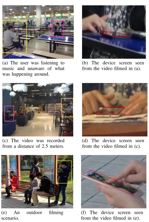
(a) The user was listening to music and unaware of what was happening around.
(b) The device screen seen from the video filmed in (a).
(c) The video was recorded from a distance of 2.5 meters.
(d) The device screen seen from the video filmed in (c).
(e) An outdoor filming scenario.
[image:2.612.58.296.106.459.2](f) The device screen seen from the video filmed in (e).
Figure 1. Examples of scenarios in which a mobile phone camera is used to film the unlocking process. In these scenarios, the camera does not need to have a clear sight of the screen.
We thoroughly evaluate our approach using 120 unique patterns collected from independent users. We show that our approach is effective in inferring candidate patterns and as a result, an attacker can unlock the target device with a success rate of over 95% (up to 97.5%) in five attempts. We demonstrate that, in contrast to many people’s belief, complex patterns do not provide stronger protection over simple patterns under our attack. According to a recent study [18], people tend to use complex patterns for important financial applications such as online banking and shopping. Our finding suggests that using pattern lock to protect sensitive information could actually be risky.
Contributions The key contribution of this paper is a new attack for Android pattern lock that has not seen in prior work. Our attack exploits techniques developed in the computer vision domain to address the key challenges highlighted above. This paper makes the following specific contributions:
• A New Attack.This is the first work to reconstruct locking patterns without relying on the content shown on the screen (Section II-B). Experimental results show that our
method can break over 95% of the lock patterns in five attempts (Section VI-A). Given that the Android operating system (OS) allows five tries before locking the device, our attack represents a real threat for pattern lock.
• Identifying New Vulnerabilities. According to a recent
study [8], direct observation techniques, e.g. shoulder surfing, are considered to be a low risk due to the close distance between the attacker and the user (in order to gain a clear sight of the device screen). As a result, many users may underestimate the dangers from using pattern lock in public places. Under our attack, filming can be carried out at a distance of 2 meters from the user and the camera does not need to directly face the target device. Such a camera setting makes our attack less likely to raise suspicion and more likely to success when compared to direct observation techniques. For instance, the video can be filmed by an adversary who pretends to interact with his phone, sitting next to the user in a public place (see Figure 1). In many similar scenarios, users will not be suspicious of the attacker’s behavior.
• New Findings. Our study suggests that complex patterns
are more vulnerable under video-based attacks (Sec-tion VI-A). This finding debunks many people’s concep-tion that more complex patterns give stronger protecconcep-tion. Therefore, our work sheds new insights on the practical use of pattern lock.
II. BACKGROUND
A. Android Pattern Lock
Pattern lock is widely used to protect sensitive information and perform authentication on Android touch-screen devices. To unlock a device protected with pattern lock, the user is asked to draw a predefined sequence of connected dots on a pattern grid1. Figure 2 (e) shows a pattern which consists of seven dots on a 3×3 grid. To form a pattern, the user starts by selecting one dot as the starting point and then swiping over multiple dots of the grid until the fingertip is lifted from the screen. There are several rules for creating an Android pattern: (1) a pattern must consist of at least four dots; (2) each dot can only be visited once; and (3) a previously unvisited dot will become visited if it is part of a horizontal, vertical or diagonal line segment of the pattern. Taking into account these constraints, the total number of possible patterns on a 3 ×3 grid is 389,112 [29]. Given the large number of possible patterns, performing brute-force attacks on Android pattern lock is ineffective, because by default the device will be automatically locked after five failed tries.
B. Threat Model
In our threat model, we assume an adversary wants to access some sensitive information from or to install malware on a target device that is protected by pattern lock. This type of attacks is mostly likely to be performed by an attacker who have physically access to the target device for a short period of time (e.g. via attending a meeting or a party where the user presents). To quickly gain access to the device, the attacker would like to obtain the user’s locking pattern in advance. The
-60 -30 0 30 60 -60
-30 0 30 60
-60 -30 0 30 60 -60
-30 0 30 60
(a) Video footage
1 2
(b) Marked tracking areas (c) Fingertip trajectory (camera s perspective)
3
(d) Transformed trajectory (user s perspective)
4
(e) Candidate patterns
5
(f) Correct pattern
[image:3.612.58.569.54.144.2]Attacker Our system Attacker
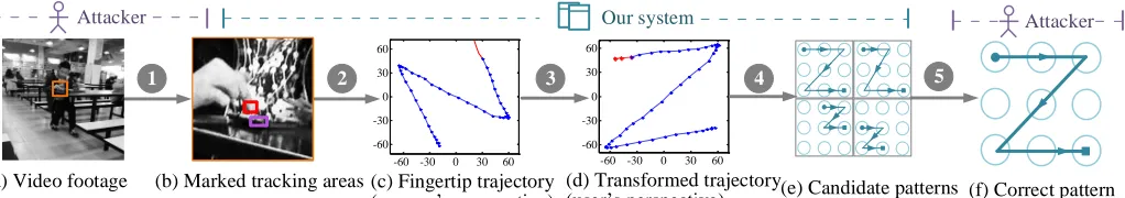
Figure 2. Overview of the attack. Our system takes in a video segment that records the unlocking process (a). The adversary first marks two areas of interest on the first video frame (b): one contains the fingertip involved in pattern drawing, and the other contains part of the device. Our system then tries to track the fingertip’s location w.r.t. to the device. The tracking algorithm produces a fingertip movement trajectory from the camera’s perspective (c) which is then transformed to the user’s perspective (d). Finally, the resulted trajectory in (d) is mapped to several candidate patterns (e) to be tested on the target device (f).
attack starts from filming how the user unlocks the device. Video recording can be done on-site or ahead of time. The video will then be processed to identify a small number of patterns to be tested on the target device. Because filming can be carried out in from a distance of as far as 2 meters using a mobile phone camera and the camera does not need to directly face the target device, this activity often will not be noticed by the user. Moreover, given that many users use the same pattern across devices and applications, the pattern obtained from one device could also be used to break the user’s other devices. We want to stress that the goal of this paper is to demonstrate the feasibility of a new attack and its implications to the use of pattern lock.
Examples of Filming Scenarios Figure 1 illustrates three scenarios where filming can be performed without raising suspicion to many users. For all the examples presented in Figure 1, the filming camera had a left- or right-front view angle from the target device and did not directly face the screen of the target device. Due to the filming distance (2-3 meters), the recoded video typically does not have a clear vision of the content displayed on the screen. This observation can be confirmed by the video snapshot placing alongside each scenario, where it is impossible to identify the content shown on the screen. The examples given in Figure 1 are some of the day-to-day scenarios where security of the user’s device can be compromised under our attack.
Assumptions Our attack requires the video footage to have a vision of the user’s fingertip that was involved in pattern drawing as well as part of the device (e.g. an edge of a phone). We believe this is a reasonable assumption because in practice many users often do not fully cover their fingers and the entire device when drawing a pattern. This is particularly true when holding a large-screen device by hands. To launch the attack, the attacker needs to know the layout of the grid, e.g. whether it is a3×3or a6×6grid. Our approach is to generate a set of candidate patterns for each of the Android pattern grids and the attacker can simply decide which set of candidate patterns to use after seeing the target device (at the time the layout of the grid will become available). However, unlike prior work on video-based attacks on keystroke based authentication [23], our approach does not require having knowledge of the console’s geometry. In other words, the size of the screen or the position of the pattern grid on the screen does not affect the accuracy of our attack. We also assume the video does not need to capture any content displayed on the screen. This assumption makes previous video-based attacks on pattern lock [1] inapplicable.
III. OVERVIEW OFOURATTACK
This section gives an overview of our attacking system which analyzes the user’s fingertip movement to infer the locking pattern. The system takes in a video segment that records the entire unlocking process. It produces a small number of candidate patterns to be tested on the target device. Figure 2 depicts the five steps of our attack:
1 Filming and Video Preprocessing:The attack begins from filming how the pattern is drawn. The video footage can be filmed at a distance of about 2 meters from the user using a mobile phone camera (or 9 meters using a digital single reflex camera). After recording, the attacker needs to cut out a video segment that contains the entire unlocking process. We have shown that it is possible to automatically identify this video segments in some scenarios (Section IV-A). After cutting out the video segment, the attacker is then asked to mark two areas of interest from one of the video frames: one area consists of the fingertip used to draw the pattern, and the other consists of part of the device (see Figure 2 (b)).
2 Track Fingertip Locations:Once the areas of interest are highlighted, a computer vision algorithm will be applied to locate the fingertip from each video frame (Section IV-B2). The algorithm aggregates the successfully tracked fingertip locations to produce a fingertip movement trajectory. This is illustrated in Figure 2 (c). Keep in mind that at this stage the tracked trajectory is presented from the camera’s perspective.
3 Filming Angle Transformation:This step transforms the tracked fingertip locations from the camera’s perspective to the user’s. We use an edge detection algorithm to automatically calculate the filming angle which is then used to perform the transformation (Section IV-C). For example, Figure 2 (c) will be transformed to Figure 2 (d) to obtain a fingertip movement trajectory from the user’s perspective.
4 Identify and Rank Candidate Patterns:In this step, our software automatically maps the tracked fingertip movement trajectory to a number of candidate patterns (Section IV-D). We rank the candidate patterns based on a heuristic described in Section IV-D2. For instance, the fingertip movement trajectory in Figure 2 (d) could be mapped to a number of candidate patterns shown in Figure 8. We show that our approach can reject most patterns to leave no more than five candidate patterns to be tried out on the target device.
IV. IMPLEMENTATIONDETAILS
A. Video preprocessing
The first step of our attack is to identify the unlocking process from the video footage. While all our participants (see Section V-A) consider this as a straightforward manual task, we developed asimple yet effectiveheuristic to automatically detect the video segment in some typical scenarios. Our heuristic is based on the following observations: (1) before or after unlocking, users often pause for a few seconds; (2) two consecutive on-screen operations (e.g. swiping, zooming etc.) typically expose some spatial-temporal motion characteristics.
To test our hypothesis, we have recorded 50 video streams (each video lasts around 2 minutes) of how ten of our partic-ipants drew patterns. During video recording, our particpartic-ipants firstly performed some on-screen activities such as web brows-ing and gambrows-ing as they wished; they then randomly opened up a pattern lock screen to draw a pattern and continued to perform other on-screen operations afterwards. We then analyzed frames that are associated with pattern drawing and those are not.
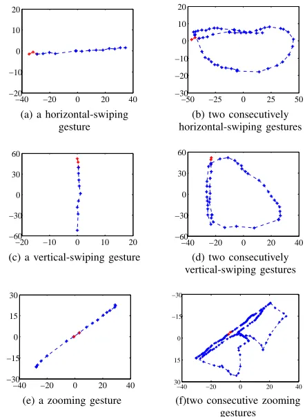
Figure 3 shows that all our participants paused at least
1.5 seconds before or after pattern drawing due to delay of the user or the device. We also found that identical on-screen activities often follow closely. For example, on several occa-sions our participants had to swipe several times to locate a program from the application list. These consecutive on-screen operations have some spatial-temporal motion characteristics that are different from pattern drawing. Figure 4 shows the spatial-temporal motion structure for two gestures, swiping and zooming, when they are performed once (a, c, e) and twice (b, d, f). This diagram indicates that the spatial-temporal motion of two identical on-sreen activities contains one or more loop structures for which pattern drawing does not have.
Our heuristic is described in Algorithm 1. The input to the algorithm is a video capturing the unlocking process, and the output of the algorithm is a time-stamp tuple, <start, end>, which marks the start and the end of a video segment. To locate the video segment of pattern drawing, we first filter out on-screen activities where the fingertip location does not change within a timeframe of 1.5 seconds (lines 4 and 11). This allows us to exclude some basic on-screen activities, such as clicking. We use the number of video frames, frameCount, as a proxy to estimate the time interval. Here, a time interval of 1.5s translates to 45 frames or 90 frames when the video was shot at 30 or 60 frames per second (FPS) respectively. We also use the spatial-temporal characteristics described above to exclude two consecutive swiping or zooming gestures (line 8). Finally, we exploit the observation that users typically paused at least 1.5s before or after unlocking to locate the start and end points of pattern drawing (line 19).
Limitations Our heuristic is likely to fail if the user was typing using a Swype-like method (i.e. entering words by sliding a finger from the first letter of a word to its last letter) during video recording. In this case, our method will identify multiple video segments of which one may contain the pattern unlock process. If multiple segments are detected, the algorithm will ask the user to confirm which video segment to use. In this scenario, the first identified segment is likely to be the correct one. In practice, an experienced attacker
1.5 1.6 1.7 1.8
0 0.2 0.4 0.6 0.8 1
The time interval (s)
[image:4.612.354.530.54.136.2]CDF
Figure 3. The cumulative distribution function (CDF) of the time interval between pattern drawing and other on-screen activities.
−40 −20 0 20 40 −20
−10 0 10 20
(a) a horizontal-swiping gesture
−50 −25 0 25 50 −30
−20 −10 0 10 20
(b) two consecutively horizontal-swiping gestures
−20 −10 0 10 20 −60
−30 0 30 60
(c) a vertical-swiping gesture
−40 −20 0 20 40 −60
−30 0 30 60
(d) two consecutively vertical-swiping gestures
−40 −20 0 20 40 −30
−15 0 15 30
(e) a zooming gesture
−40 −20 0 20 40
30 15 0 −15 −30
(f)two consecutive zooming gestures
Figure 4. Spatial-temporal characteristics for performing an on-screen gesture once (a, c, e) and twice (b, d, f).
would wait patiently to avoid this complicated situation by finding the right time for filming (e.g. for a screen lock, the time is just after the device is retrieved). The attacker could also watch the video to manually cut it to ensure the obtain the correct video segment. It is worthwhile to mention that automatically identifying the pattern unlocking process is not central to our attack because an experienced attacker often can obtain a quality video input used the manual methods described above. Despite its limitations, our algorithm can reduce the efforts involved in some common scenarios.
B. Track fingertip locations
[image:4.612.331.552.169.471.2]x=265.00 y=364.00 x=156.00 y=454.00 x=109.00 y= -90.00
(a) The first video frame
x=275.62 y=324.86 x=156.22 y=456.98 x= -119.40 y=132.12
(b) A middle video frame
x=310.70 y=278.00
x=157.40 y=437.94 x= -153.30 y=159.94
(c) The last video frame
-60 -30 0 30 60 -60
-30 0 30 60
[image:5.612.86.539.63.146.2](d) Fingertip movement trajectory
Figure 5. Tracking the fingertip movement trajectory. For each video frame, the system tracks two areas: one surrounds the fingertip and the other covers the edge of the device. The fingertip position is determined by computing the relative coordinates of the central points of the two areas. The red points highlighted in the final results (d) are the touching points tracked from the three video frames.
Algorithm 1 Unlocking process identification heuristic
Input:
IV: Video footage
f rameCount: Pause threshold before or after unlocking Output:
<start,end>: Start and end of the unlocking video segment 1: f rames[]←getV ideoF rames(IV)
2: LEN ←getF ramesLen(f rames[])
3: fori= 1 :LEN−f rameCountdo
4: sL ← hasF ingertipChanged(f rames[i :
i+f rameCount])
5: if!sLthen
6: sN o=i+f rameCount
7: forj=sN o:LEN do
8: ifcheckLoop(f rames[j:LEN])then
9: eN o=i
10: break;
11: else if !hasF ingertipChanged(f rames[j : j +
f rameCount])then
12: eN o=i
13: break;
14: end if
15: end for
16: break;
17: end if
18: end for
19: < start, end >←getT argetV ideo(f rames[], sN o, eN o)
of the video segment (see Figure 2 b). The algorithm tries to localize the fingertip from each video frame and aggregates the successfully tracked locations to produce a fingertip movement trajectory as an output (see Figure 2 c).
1) Generate The Fingertip Movement Trajectory: The TLD
algorithm automatically detects objects based on the examples seen from previous frames. For each tracked object, the algo-rithm generates a confidence between 0 and 1. A tracking is considered to be successfully if the confidence is greater than a threshold. We set this threshold to 0.5 which is found to give good performance in our initial design experiments using 20 patterns2. TLD has three modules: (1) a tracker that follows objects across consecutive frames under the assumption that the frame-to-frame motion is limited and objects are visible; (2) a detector to fully scan each individual frame to localize all appearances of the objects; and (3) a learner that estimates errors of the detector and updates the detector to avoid these errors in future frames.
2To provide a fair evaluation, the patterns used in our initial test runs in the design phase are different from the ones used later in evaluation.
The TLD learner automatically extracts features from the area of interest to build a K-Nearest Neighbor classifier [13] which is a part of the detector. In the following frames, the learner estimates the detection errors and generates new train-ing examples (i.e. new appearances of the object) arose from object motion to re-train the classifier to avoid these errors. For each video frame, TLD calculates the tracking confidence and if the confidence is lower than the predefined threshold, the result of this particular frame will be discarded. This allows the algorithm to tolerate a certain degree of detection errors. Finally, the successfully detected object locations will be put onto a single image as the output. Detailed discussion of TLD can be found at [15]. Sometimes the algorithm may fail to detect the objects in many video frames due to poor selections of interesting areas. If this happens, our system will ask the user to re-select the areas to track. We have also extended TLD to report when a fingertip position is seen on the footage. This temporal information is recorded as the number of video frames seen so far. This is used to separate two possibly overlapping line segments described in Section IV-D.
2) Camera Shake Calibration: By default, the TLD
algo-rithm reports the position of a tracked object with respect to the top-left pixel of the video frame. However, videos recorded by a hand-held device is not always perfectly steady due to camera shake. As a result, the top-left pixel of a video frame may appear in a different location in later frames. This can drastically affect the precision of fingertip localization, leading to misidentification of patterns.
Our approach to cancel camera shake is to record the fingertip location with respect to a fixed point of the target device. To do so, we track two areas from each video frame. One area is an edge of the device and the other is the fingertip. Both areas are highlighted on the first frame by the user. The location of a successfully tracked fingertip is reported as the the relative coordinates of the two center points of the marked areas. This approach can also be used to calibrate the slight movements of the target device when drawing the pattern.
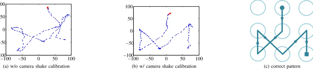
Example: To illustrate how our camera-shake calibration
−100 −50 0 50 100 −100
−50 0 50 100
(a) w/o camera shake calibration
−100 −50 0 50 100
−100 −50 0 50 100
[image:6.612.62.565.60.175.2](b) w/ camera shake calibration (c) correct pattern
Figure 6. The resulted fingertip movement trajectories without (a) and with (b) camera-shake calibration. The correct pattern is shown in (c). To aid clarity we have transformed (a) and (b) to the user’s perspective.
100 200 300 400
150 100 50
[image:6.612.72.279.213.301.2]
Figure 7. Filming angle calculation. The filming angle,θ, is the angle between the edge line of the device and a vertical line.
Figure 6 shows the results when using TLD to process a video that was filmed with some camera shake effects. Here we show the results without (Figure 6 a) and with (Figure 6 b) camera-shake calibration. To aid clarity, we have converted the trajectories into the user’s perspective. Without camera-shake calibration, the resulted trajectory is significantly different from the actual pattern shown in Figure 6 (c). Because of this great difference, using Figure 6 (a) will lead to misidentifica-tion of candidate patterns. By contrast, processing the same video with camera-shake calibration produces Figure 6 (b). Clearly, this figure is more alike the correct pattern.
C. Filming angle transformation
In practice, the filming camera will not directly face the target device to avoid raising suspicion by the user. As a result, the fingertip movement trajectory generated by the tracking algorithm will look differently from the actual pattern. For example, for the pattern presented in Figure 2 (a), if the video is filmed from the attacker’s front-left to the target device (i.e. with a filming angle of approximate 45 degrees), we get the trajectory shown in Figure 2 (c). Using this trajectory without any postprocessing will lead to misidentification of candidate patterns. Therefore, we must transform the resulted trajectory to the user’s view point. To do so, we need to estimate the angle between the filming camera and the target device. Our approach is described as follows.
We use an edge detection algorithm called Line Segment Detector (LSD) [12] to detect the longer edge of the device. The filming angle is the angle between the detected edge line and a vertical line. This is illustrated in Figure 7. In Section VI-E, we show that a slight estimation error of the filming angle has little impact on the success of the attack. By default, we assume that the pattern grid is presented in
the portrait mode3. If this is not the case, i.e. the pattern grid
is shown in the landscape mode, we need to use the shorter edge of the device to calculate the filming angle. We believe that an attacker interested in a particular target would have some knowledge of how the pattern grid of the target device is presented under different orientation modes and be able to identify the device orientation by watching the video. There are also other methods to be used to identify the filming angle [28].
Based on the estimated filming angle, θ, we use the following formula to transform the tracked fingertip movement trajectory from the camera’s view point to the user’s:
S=T S0 , T =
cosθ −sinθ
sinθ cosθ
(1)
whereT is a Transformation Matrix, S0 is the coordinate of a point of the tracked trajectory, and S is the resulted coordinate after the transformation. For each video frame, our algorithm individually calculates the filming angle and perform the transformation, because the filming angle may change across video frames.
D. Identify and rank candidate patterns
In this step, the fingertip movement trajectory will be mapped to a number of candidate patterns to be tested on the target device. Our goal in this step is to exclude as many patterns as possible and only leave the most-likely patterns to be tried out on the target device. Our approach is to use the geometry information of the fingertip movement trajectory, i.e. the length and direction of line segments and the number of turning points, to reject patterns that do not satisfy certain criteria. In this section, we first describe how to identify overlapping line segments and extract length and direction information before presenting how to use the extracted infor-mation to identify and rank candidate patterns.
1) Extracting Structure Information: A pattern can be
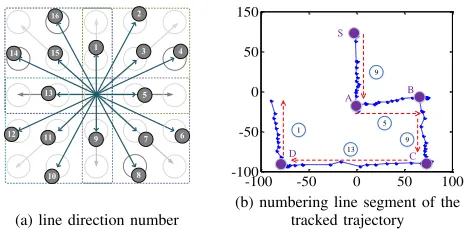
defined as a collection of line segments where each line segment has two properties: the length of the line, l, and the direction of the line, d. Figure 11 shows all the possible directions of a 3×3 pattern grid. We define a pattern,P, as a collection of line segment prosperities, P ={L, D}. Here L ={l1, l2,· · · , ln} is a collection of the lengths of all line
a(1) a(2) a(3) a(4) a(5)
b(1) b(2) b(3) b(4) b(5)
c(1) c(2) c(3) c(4) c(5)
[image:7.612.64.287.50.268.2]d(1) d(2) d(3) d(4) d(5)
Figure 8. Possible mappings for the tracked fingertip movement trajectory presented in Figure 2 (d).
-100 -50 0 50 100 -100
-50 0 50 100
A
B C
D S
E
(a) tracked fingertip movement
S
A
B
C
D
E
[image:7.612.323.566.63.162.2](b) pattern example
Figure 9. This figure shows the tracked fingertip movement trajectory (a) of a pattern (b). Point S on (a) is the the starting point and points A, B, C, and D on (b) represent four turning points.
Algorithm 2 Line Segment Identification
Input:
structT[]: Temporal information of each tracked location
timeT h: Threshold of whether two line segments are overlapping Output:
tp[]Turning points of fingertip movement.
1: for eachfingertip movement with temporal sequencesT[]do
2: tpN um= 0;
3: structlines[]←getLines(T[])
4: lN um←getLinesN umber(lines[])
5: fori= 1 :lN umdo
6: ifcheckOverlap(lines[i], timeT h)then 7: p[tpN um+ +]←getOverlapP oints(line[i])
8: end if
9: p[tpN um+ +]←getT urningP oints(line[i])
10: end for
11: end for
12: tp[] =p[0 :end−1]
segments (that are numbered from 1ton) of the pattern, and D = {d1, d2,· · · , dn} is the collection of directions for all line segments inL. Algorithm 3 describes howP is extracted. We extract the length and the direction of each line segment from the tracked fingertip movement trajectory and store them into arrays L[]andD[]respectively.
Identify Line SegmentsThe first step of geometry information
-100 -50 0 50 100
-40 -20 0 20 40
Line 1 Line 2 Line 3 timeframes
(a) overlapping lines
90 100 110
24 25 26
Line 1 Line 2
1 8
111013 9 12 14
(b) enlargement of timeframe
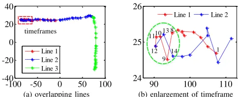
Figure 10. Separating two overlapping line segments by checking the number of overlapping points within a timeframe.
extraction is to identify individual line segments from the trajectory. This can be achieved by finding turning points, the start and the end points of the pattern, because two points define a line segment. For example, turning points, A and B, in Figure 9 defines a line segment, AB. In Algorithm 2, we use a linear fitting method [17] to discover turning points (line 3). A specific challenge here is how to separate two overlapping line segments (see Figure 12 c for an example). It is to note that up to two lines can be overlapped on a pattern grid. The naive linear fitting algorithm would consider two overlapping segments to be a single line as their points stay close to each other. We overcome this problem by using the temporal information (that is recorded by the tracking algorithm) to separate two overlapping points. To do so, we visit all tracked points of each line segment given by the linear fitting algorithm (line 5) within a timeframe (timeTh) of 20 video frames for a video of 30 FPS (40 for a video of 60 FPS). For each point, we calculate its Euclidean distances to all other points within the timeframe. We consider two points to be overlapping if their distance is less than 5 pixels. For a video shot at 30 FPS, we consider there exist two overlapping line segments if 5 (10 for a 60 FPS video) or more overlapping points in the timeframe. Again, these threshold values were determined through our initial design experiments. Finally, we consider the center of all points as the turning point of the two overlapping line segments and use turning point to separate the two lines.
Example: As an example, consider a fingertip movement
trajectory shown in Figure 10 (a). The red rectangle on the figure is a timeframe consisting of 20 tracked points. If we zoom in on the timeframe, we get Figure 10 (b) where a point is labelled with a frame number according to when the point was seen, starting from 1 for the earliest point. In this example, there are more than 6 overlapping points in the timeframe, which are marked by a green circle. We use the center point (No.10) of the overlapping points as the turning point to separate the two line segments.
Extract the Line Length The physical length of a line segment depends on the sizes of the screen and the pattern grid, and the space between two touch dots. To ensure our approach is independent of the device, we normalize the physical length of a line segment to the shortest line found on the tracked trajectory. For the example shown in Figure 9 (a), the line lengths for segments, SA, AB, BC, CD, and DE, are
[image:7.612.60.294.302.402.2]16
1
14 3 4
5
6 7
8 11
13 15
12
2
10 9
(a) line direction number
-100 -50 0 50 100
-100 -50 0 50 150
9
5
13 1
9
S
A B
C D
[image:8.612.319.572.52.412.2](b) numbering line segment of the tracked trajectory
Figure 11. All possible line directions for a3×3Android pattern grid.
Table I. MAPPINGS FROM LINE SLOPES AND FINGERTIP-HORIZONTAL MOVEMENTS TO DIRECTION NUMBERS
Direction No. 1 2 3 4 5 6 7 8
slope (L→R) +∞ 2 1 1
2 0 −
1
2 −1 −2
Direction No. 9 10 11 12 13 14 15 16
slope (R →L) −∞ 2 1 12 0 −1
2 −1 −2
Extract Direction InformationIn addition to the line length, we also want to know to which direction the finger moves. This information is useful for inferring which dots are selected to unlock the pattern. Figure 11 (a) shows all possible 16 directions on a3×3pattern grid. The directions are numbered from 1 to 16 in clockwise. For each line segment of the tracked trajectory, we calculate its line slope and the horizontal movement of the finger (i.e. left → right or vice versa). This information will then be checked against Table I to determine the direction number of the line segment. The horizontal movement of the fingertip is determined by first using the temporal information to find out the start and the end points of the line and then comparing the horizontal coordinates of the two points. The line slope is also computed based on the coordinates of the start and the end points of the line segment. Figure 11 (b) gives the direction number of each tracked line segment of a fingertip movement trajectory.
2) Map the Tracked Trajectory to Candidate Patterns: In
this step, we use the extracted geometry information to map the fingertip movement trajectory to a small number of candidate patterns which will then be ranked using a heuristic. This process is described in Algorithm 3.
Identify Candidate Patterns Our implementation simply enumerates all possible patterns for a given pattern grid to identify candidate patterns, starting from the top-left touch point. We reject patterns that do not meet the requirements that the correct pattern is expected to have. The requirements are the number of line segments (this is checked by counting the number of turning points), and the length and the direction for each line segment. This is anautomaticprocess performed by our software system without any user involvement. We con-sider two line segments having the same length and slope if the difference between them is less than a threshold. Specifically, the relative length threshold,lengthT h, is set to 1.12 and the slope threshold,directionT h, is set to 0.25. To determine the thresholds, we have evaluated a range of possible values in our initial design experiments to chose the best performing values.
Example: We use the pattern depicted in Figure 2 as an
example to describe our algorithm. Figure 8 gives several
Algorithm 3 Candidate Pattern Identification Algorithm
Input:
L[]: Relative line length
D[]: Direction number (see Figure 11)
tn: Number of turning points of fingertip trajectory lengthT h: Threshold of considering two lines to have the same length
directionT h: Threshold of considering two lines to be in the same direction
Output:
P[]: Candidate patterns
1: for eachpossible patternpwithtnturning pointsdo 2: n←getLineN umber(P[])
3: pL[]←getRelativeLength(p)
/*Relatvie line length for patternp*/
4: pD[]←getDirection(p)
5: ifmatch(pL[],L[],lengthT h)then 6: ifmatch(pD[],D[],directionT h)then
7: P[]←p
8: end if
9: end if 10: end for
11: P[]←sort(P[])
2
2 2 5
1
2
(a) line length (b) line intersection
(c) overlapping lines
Figure 12. Illustrations of the terminologies used in Equation 2.
possible mappings for the fingertip movement trajectory shown in Figure 2 (d). For this particular trajectory, the collections of lengths and directions areL={l,√2l, l} andD={5,11,5} respectively. Any pattern that does not meet L or D should not be considered as a candidate pattern for this trajectory. For this reason, Figure 8 a(1)–a(5) will be rejected. Take Figure 8 a(1) as an example, the line lengths and directions for all four line segments of this pattern are{l,
√ 5
2 l, l}and{5,12,5}
respectively. It does not meet the expectedLorD and should be rejected. The patterns presented in b(1)–b(5) and c(1)–c(5) of Figure 8) will also be rejected for the same reason.
[image:8.612.58.292.57.174.2](a) Example patterns belong to the simple category.
(b) Example patterns belong to the median category.
[image:9.612.63.287.49.215.2](c) Example patterns belong to the complex category.
Figure 13. Examples of patterns collected from our participants. Patterns are grouped into simple,medianandcomplexcategories, according to their complexity scores.
complexity score: 43.8
complexity score: 44.7
complexity score: 46.8
Figure 14. Three most complex patterns on a3×3grid based on Equation 2.
V. EXPERIMENTALSETUP
A. Data Collection
The patterns used in our evaluation were collected from users who use at least one Android device (a smartphone or a tablet) on a daily basis. To collect the patterns, we have distributed over 1,000 survey forms and collected back 215 valid forms, resulting in 120 unique patterns4. Our participants include 95 females and 120 males who were undergraduate or postgraduate students in our institution. The majority of our participants are in an age group of under 30.
To collect the patterns, we have conducted a “pen-and-paper” survey by asking participants to fill in an anonymized questionnaire. The questionnaire and survey were approved by the research ethics board (REB) of our institution. We have made sure that our survey complied with strict privacy regulations. For example, we did not collect any personally identifiable information other than the gender and age group of the participant. Our participants were well informed on the purpose of the study and how the data will be managed and used. The survey forms were distributed as voluntary homework so that the participants can take the survey form away to fill in. Users were invited to return the survey form anonymously within three weeks to a dedicated, locked mailbox, if they wish to participate in the study. To avoid a user submits multiple copies of the same form, each survey form is given a unique, randomly generated 32-digital number.
Overall, 37.6% of our participants confirmed that they use pattern lock as the screen lock to protect their Android devices on a daily basis; and 33% of those who do not use a pattern
4Available to be downloaded at: https://dx.doi.org/10.17635/lancaster/
researchdata/113andhttps://github.com/yeguixin/patterns.
6 . 3 4 1 3 . 0 8 1 9 . 8 2 2 6 . 5 6 3 3 . 3 0 4 0 . 0 4
0
2
4
6
8
N
u
m
b
er
o
f
p
at
te
rn
l
o
ck
s
C o m p l e x i t y s c o r e
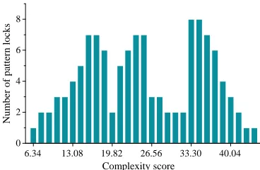
Figure 15. The distribution of complexity scores for the patterns given by our participants.
as their screen lock said that they are often required to use a pattern for authentication by an application like Alipay. Furthermore, 60% of our participants also indicated that the pattern they provided is currently being used or have been used in the past by themselves. Other participants (often those did not use a locking pattern on a daily basis) indicated that they have provided a pattern which they would like to use if a locking pattern is required. Based on this information, we are confident that our patterns represent some of the real world patterns. Finally, all participants believe that a complex pattern provides stronger protection than a simple one.
B. Pattern Complexity Classification
We quantify the complexity of a pattern using the complex-ity (strength) score proposed in [27]. The complexcomplex-ity score, CSP, of a pattern,P, is defined as:
CSP =SP ×log2(LP+IP +OP) (2)
where SP is the number of connected dots, LP is the the total length of all line segments that form the pattern (see Figure 12 a), IP are the number of intersections (which are also termed as “knight moves” in some prior work [30], see Figure 12 b) and OP are the number of overlapping linear segments (see Figure 12 c). To calculate the line length, we assume the length between two horizontally or vertically adjunct dots is one. Thus, our method is independent of the size of the screen and the grid.
Intuitively, the more connected dots (SP), line segments (LP), intersections (IP) and overlapping line segments (OP) that a pattern has, the more complex it is. For example, the patterns shown in Figure 13 (c) use all the nine dots of the grid, and have at least seven line segments and three intersections.
Base on the complexity score, we divide the collected patterns into three complexity categories: simple,medianand
[image:9.612.351.535.52.172.2] [image:9.612.55.290.257.336.2]Table II. SCREEN SIZES FOR THE TEST PHONES
Size
Brands
MI4 Honor7 Note4
Height(cm)×Width(cm) 13.9×6.9 14.3×7.2 15.4×7.9
C. Video Recording and Preprocessing
Recording Devices We used three smartphones for video recording: an Apple iPhone4S, a Xiaomi MI4 and a Meizu2 phones. Each mobile phone was used to record 40 patterns with a 1080p HD resolution of 30 FPS under different settings.
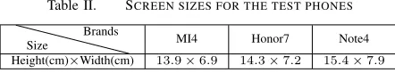
User Participation We recruited ten postgraduate students (five male and five female students) from our institution to reproduce the 120 patterns (collected from the users) and the 60 most complex patterns (see Section VI-A) on three target mobile phones: a Xiaomi MI4, a Huawei Honor7 and a Samsung Note4 smartphones. Table II lists the screen size for each target mobile phone.
Video Recording SetupBy default, we used the Android3×
3 native pattern grid, but we evaluated our approach using other pattern grids with different sizes in Section VI-G. We recorded each pattern under three filming angles, 45, 90 and 135 degrees, by placing the camera on the left-front, front, and right-front of the target device respectively. By default, the video was recorded indoor during daytime under a natural lighting condition. In Section VI-D we evaluated our approach under different lighting conditions both indoor and outdoor. By default, videos were recorded at a distance of 2 meters from the target device and we evaluated the impact of the filming distance in Section VI-G.
Video Filming Before recording, our participants were given the opportunity to practice a pattern several times, so that they can draw the pattern at their natural speed. On average, this practice session took 10 trails per user per pattern. When drawing the pattern, some participants sat, while others stood, some hold the device by hands, while others placed it on a table. Each pattern was drawn on three target devices and recorded under three filming angles. Thus, for the 120 patterns collected from users, we recorded 1,080 videos in total.
Video Preprocessing For each video stream, we used the algorithm described in Section IV-A to cut out the video segment of the unlocking process. We left around 200 to 300 milliseconds of the video segment before and after the pattern unlocking process. To track the fingertip locations, we used Windows Movie Make to highlight two areas of interest on the first frame of the video segment: one area surrounds the fingertip, and the other contains an edge of the phone (see Section IV-B2).
ImplementationOur prototyped attacking system built upon a TLD library [14]. The developed software ran on an Intel Core i5 PC with 8GB RAM. The operating system is Windows 10. Our implementation can be ported onto Android or Apple iOS systems, which is our future work. On our evaluation platform, our software takes less than 30 seconds to process a video to produce candidate patterns.
VI. EXPERIMENTALRESULTS
In this section, we first present the overall success rate for cracking the 120 patterns collected from our participants plus the top 60 most complex patterns on a3×3 pattern grid.
Simple Median Complex 0%
20% 40% 60% 80% 100%
The complexity of pattern locks
Cracking success rate
1attempt 2attempts 3attempts 4attempts 5attempts
Figure 16. For each pattern category, the figure shows the success rate using no more than 1, 2, 3, 4 and 5 attempts.
Our results show that our approach can successfully crack over 95% of the patterns using no more than five attempts. We then analyze how the success rate is affected by the filming distance, filming angles and camera shake. Finally, we demonstrate that direct observations lead to poor performance before evaluating our approach on alternative pattern grids.
A. Overall Success Rate
Result 1: We can successfully crack over 95% of the patterns in five attempts and complex patterns are less secure compared to simple patterns under our attack.
In this experiment, videos were recorded from a distance of 2 meters away from the target device. This mimics a scenario where the adversary sits at the next table to the user in a public space (e.g. a restaurant). The smartphones used for filming in this experiment were hand-held. Figure 16 shows the success rate for cracking different types of patterns within 1, 2, 3, 4 and 5 attempts. For all the patterns used in this evaluation, our approach does not generate more than five candidate patterns. For complex patterns, we are able to crack all except one (with a 97.5% success rate) in the first attempt. For simple and median patterns, the success rate increases with more tries. In one attempt, we are able to successfully crack 60% and 87.5% of the simple and median patterns respectively. With two attempts, the success rate increases to 87.5%, and 95% for simple and median patterns respectively. Using five attempts, we are able to crack all simple patterns and all but one median patterns. The reason that we failed on one median and one complex patterns is because of some blur motions of the video footage (probably caused by the video compressing algorithm), which leads to many tracking failures. But we are able to crack the same pattern using a video filmed by a different device. It is important to note that the Android OS will not lock the device unless seeing more than five failed tries [11]. This means, in practice, our approach is able to successfully crack most locking patterns.
[image:10.612.353.536.54.163.2]1 2 3 4 5 0
10 20 30 40
Number of candidate patterns
Number of patterns
[image:11.612.84.269.53.165.2]Simple Median Complex
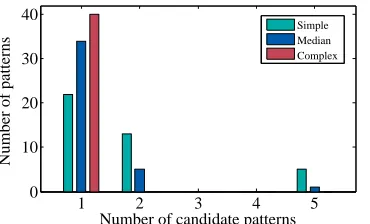
[image:11.612.78.272.207.248.2]Figure 17. The distribution of candidate patterns for each category. No more than 5 candidate patterns were generated by our algorithm.
Table III. TRACKING PRECISION VS FILMING DISTANCE
Distance 1 m 2 m 3 m 3.5 m
fingertip 100% 98.7% 80.9% 68%
device edge 100% 99.4% 90.6% 69%
We also evaluated our approach using the top 60 most complex patterns (according to Equation 2) on a 3×3 grid. To evaluate our approach on a wide range of patterns, we exclude patterns that are simply a rotation to an already chosen pattern. Figure 14 illustrates three highly complex patterns which have a complexity score between 43.8 and 46.8. The three patterns use all the nine dots of the grid and have a larger number of line segments, intersections and overlapping lines when compared to simpler patterns. Because of their complex graphical structures, it would be hard to remember these patterns using direct observation techniques. In this experiment, we can crack all the complex patterns in one attempt. This result reinforces our claim that complex patterns are less security under video-based attacks.
B. Impact of Filming Distances
Result 2: We can crack over 80% of the patterns in five attempts, if the video was filmed using a smartphone within a distance of 2.5 meters away from the target.
We would like to know how the filming distance affects the success rate of the attack. To do so, we used all the 120 collected patterns and we varied the filming distance from 1 meter to 3.5 meters. Figure 19 shows how the cracking success rate changes as the filming distance increases. There is slight differences in the success rate between this diagram and Figure 16 because we used less patterns in this experiment. When the filming distance is less than 2 meters, our approach can crack all patterns in five attempts. The success rate drops significantly when the filming distance is greater than 2.5 meters. The quality of the video filmed by a mobile phone tends to drop significantly with many object deformations. The degradation of the video quality makes it difficult for the TLD algorithm to successfully track objects across video frames. This is confirmed by Table III which shows that the tracking precision for the fingertip and the device edge drops from around 99% to 68% when the filming distance increases from 2 meters to 3.5 meters. The increased tracking failures result in an increased number of missing points on the tracked trajectory, leading to a deteriorative performance in identifying candidate patterns. This can be seen from Figure 18 where the quality of tracking clearly decreases when the filming distance is greater than 3 meters. Nonetheless, our approach can achieve
a high success rate when the filming distance within 2.5 meters. Such a distance allows an attacker to record the video without raising suspicions in many day-to-day scenarios (some of these are described in Figure 1).
We also evaluated our approach on videos filmed using a Nikon D90 single-lens reflex (SLR) camera with a low-end 105mm lens. The SLR camera was placed from a distance of 9 meters away from the target device. For this set of videos, we are able to achieve the same performance when compared to using videos filmed by a mobile phone camera with a 2-meter filming distance. The further filming distance is largely due to better video quality brought by the advanced SLR camera and the lens. Therefore, in practice, an attacker can also use a professional video recording device to launch the attack from a further distance.
C. Impact of Camera Shake
Result 3:Our method can tolerate a certain degree of camera shake in the hand-held mode.
In this experiment, we used an IPhone4S smartphone to record how a pattern is drawn on a Huawei Honor7 phone. This experiment was carried out under three settings: fixed, hand-heldandshaky, where the filming device was respectively fixed using a tripod, hand-held, and hand-held but with constant movements of approximate 2cm in the horizontal or the vertical directions. The recording device was placed on the left-front, front, and right-front of the target device. In the experiment, we fixed the target device on a table using double-sided tapes.
We use a reference point to quantify camera shake. The point is the center position of an area of the target device. The area is marked by a boundary box on the first frame (see Figure 5). We calculate the difference (in terms of pixels) for where the reference point was seen in two consecutive video frames. We then use the difference to measure the degree of camera shake. Figure 20 shows the cumulative distribution function (CDF) of camera shake under the three different filming settings. Here, the wider the distribution is, the less steady the filming is. The shaky mode is least stable where the difference of the reference point between two video frames can be up to 250 pixels.
Figure 21 shows that our approach has the same perfor-mance under the hand-held and the fixed modes. The modest camera sake under the hand-held mode has little impact on performance thanks to our camera-shake-calibration method. We observe deteriorative performance under the shaky mode, but the performance degradation is modest (80% vs 97% in 5 attempts). In reality, an attacker would avoid drastic camera shake by firmly holding the video recording device.
D. Impact of Lighting Conditions
Result 4:Low-light has a negative impact on the success rate of the attack but our approach can still break over 70% of the patterns when the video was filmed in a low-light environment.
−80 −40 0 40 80 −70
−35 0 35 70
(a)
−80 −40 0 40 80
−80 −40 0 40 80
(b)
−80 −40 0 40 80
−80 −40 0 40 80
[image:12.612.92.537.60.154.2](c) (d)
Figure 18. Tracked fingertip trajectories (user’s perspective) for the pattern shown in (d) from a video filmed from a distance of 2m (a), 3m (b), and 3.5m (c) respectively away from the target device. The tracking quality decreases when the filming distance is greater than 3m.
1 1.5 2 2.5 3 3.5
0% 20% 40% 60% 80% 100%
Distance(Meter)
Cracking success rate
[image:12.612.53.268.186.414.2]1 attempt 2 attempts 3 attempts 4 attempts 5 attempts
Figure 19. Impact of the filming distance.
−1500 −100 −50 0 50 100 150
0.2 0.4 0.6 0.8 1
The distance between video frames
CDF
[image:12.612.316.579.196.350.2]fixed hand−held shaky
Figure 20. The cumulative distribution function (CDF) for different video recording modes.
1 2 3 4 5
0% 20% 40% 60% 80% 100%
The number of sucessfull attempts
Cracking success rate
shaky hand−held fixed
Figure 21. Impact of camera shake. Our approach has the same success rate under the hand-held and the fixed modes and the performance degradation under the shaky mode is modest.
of the day-to-day scenarios where filming can take place. For each setting, we tested all the 120 patterns on a Xiaomi MI4 phone and used an iPhone4S phone to record the video. The filming camera was place on the left-front, front, and the right-front of the target device from a distance of 2 meters.
Figure 22 shows that the success rate increases when video filming were performed in a brighter lighting condition as the light intensity changes from 55 lux to 9500 lux. This is expected as low-light leads to increased video noise, blurred motion and poor focus, which all have a negative impact on the TLD algorithm. Nonetheless, our attack can still crack over 70% of the patterns in a filming environment with low light.
Table IV. LIGHTINGCONDITIONS
Scenarios Indoor Indoor Indoor Outdoor
Time nighttime nighttime daytime daytime
Light Source warm LED white fluorescent sunlight sunlight
Light Intensity (Lux) 55−70 70−100 150–240 500–9500
5 5 7 0 1 5 0 - 2 4 0 5 0 0 - 9 5 0 0 7 0 %
8 0 % 9 0 % 1 0 0 %
C
ra
ck
in
g
s
u
cc
es
s
ra
te
D i f f e r e n t l i g h t c o n d i t i o n s ( L u x )
[image:12.612.354.534.386.487.2]S i m p l e M e d i a n C o m p l e x
Figure 22. The cracking success rate within five attempts under different lighting conditions.
0 degree 5 degrees 10 degrees 20%
40% 60% 80% 100%
Simple Median Complex
Figure 23. Impact of estimation errors of filming angles.
E. Impact of Filming Angle Estimation
Result 5:Our attack performs well when the error of filming angle estimation is less than 5 degrees.
The attack needs to transform the fingertip movement trajectory to the user’s perspective based on an estimation of the filming angle (Section IV-C). Because our filming angle estimation algorithm gives highly accurate results, we did not find the estimation error to be a problem in experiments. Nonetheless, it is worth studying how the estimation error affects the success rate of our attack. To do so, we deliberately added an error of 5-10 degrees to the estimation.
Figure 23 shows the results of this experiment. When the error is less than ±5 degrees, there is little impact on
complex patterns and no impact at all on simple and median
[image:12.612.85.266.445.546.2]estimation error is 10 degrees from the true value, on average, 0.8, 2.6 and 4.2 line segments per pattern respectively will be incorrectly labelled for simple,median andcomplex patterns. This explains why the success rate for complex patterns drops significantly when there is an error of 10 degrees.
F. Inferring Patterns with Eyes
Result 6:Our attacking methodology significantly outperform direct observation techniques.
In this experiment, we investigate whether an attacker can infer the pattern by simply watching the video or through direct observations. To answer this question, we asked each of our 10 participants to watch 60 videos (where a pattern was drawn by other participants) to guess the pattern. We only played the video segment during which a pattern is drawn to the participant (around 3 seconds per video). To familiarize participants with the process, we played five sample videos and showed the correct patterns at the end of each video to our participants before the experiment. Each participant then had 10 minutes to watch a video and five chances to guess a pattern. They could adjust the playing speed and replay the video multiple times as they wished.
Figure 24 (a) shows the success rate of pattern guessing with bare eyes. Our participants correctly guessed for nearly half of the simple patterns in five attempts. However, they found that it is difficult to infer complex patterns with many line segments, overlapping lines and intersections. The success rate of guessing complex patterns is less than 10% in five attempts. This is not a surprising result because although it is possible to correctly guess patterns with simple structures by watching the video, doing so for patterns with more complex structures is much harder.
We also asked participants to directly observe how a pattern was drawn from a distance of 2 meters away from the target device. The intuition behind this evaluation is that human eyes can catch richer information over a video camera. The results of this experiment are shown in Figure 24 (b). As can be seen from the diagram, although the success rate is improved compared to directly watching the video, the chances for guessing the correct pattern in 5 attempts are quite low. In fact, the success rates are just 48.3%, 38.3% and 11.7% respectively for simple, median and complex patterns.
G. Evaluation on Other Pattern Grids
Result 7: A pattern grid with more dots provides stronger protection but our attack can still crack most of the patterns.
There are a few applications (such as CyanLock) and customized ROMs available to increase the size of the pattern grid from 3 ×3 to 4 ×4, 5×5, and 6 ×6. Although a
3 ×3 grid remains a popular choice (as it is supported by the native Android OS), it is worth studying whether having more touch dots on a pattern grid leads to stronger security. In this experiment, we first ranked all possible patterns for each grid setting in ascending order according to their complexity scores. We then equally divided the patterns into three groups, simple, medium and complex, and asked our participants to randomly select 20 patterns from each group for evaluation. We report the success rate of our attack within five attempts.
1 2 3 4 5
0% 10% 20% 30% 40% 50%
Number of attempts
Cracking success rate
Simple Median Complex
(a) video watching
1 2 3 4 5
0% 10% 20% 30% 40% 50%
Number of attempts
Cracking success rate
Simple Median Complex
[image:13.612.352.535.53.300.2](b) direct observations
Figure 24. Success rates of guessing patterns through watching the video (a) or direct observations (b).
Simple Median Complex
60% 70% 80% 90% 100%
[image:13.612.354.535.350.448.2]Cracking success rate 4*4 5*5 6*6
Figure 25. Success rates of our attack for different locking grids.
In the experiments, we have adapted our algorithms for each grid setting by adjusting the algorithm parameters (such as the line direction numbers).
VII. DISCUSSIONS
A. Potential Countermeasures
The success of our attack depends on three factors: (1) knowledge of the pattern grid; (2) a decent quality video footage allowing the algorithm to track the fingertip movement; (3) successfully identifying a video segment that captures the entire process of pattern drawing.
For the first factor, the attacker can obtain relevant in-formation via analyzing a device installed with the same operating system and applications as the target. Randomization techniques such as randomized pictures [6, 24] could be a solution for the first factor. However, randomization-based solutions often come at the cost of poorer usability. This can prevent them to be used at a large scale. Regarding the second factor, there are ways, such as KALEIDO [35], to prevent unauthorized videotaping by dynamically changing the colour and brightness of the screen to confuse the filming camera. A non-technical solution for this aspect would be to educate users to fully cover their fingers when drawing a pattern. But doing this on a large-screen device could be awkward especially when the device is held by one hand. For the third factor, the attacker’s solution depends on the type of the pattern. For a screen lock, pattern drawing is the first activity (except for receiving a phone call or making an emergency call) when the device is retrieved. Therefore, identifying the video segment is straightforward. When the pattern is used by applications, we have observed that users typically pause for a few seconds before or after entering the pattern. Therefore, an experienced attacker should also be able to identify the video segment in case our automatic algorithm (presented in Section IV-A) fails to do so. A potential countermeasure is to mix pattern unlocking with other on-screen activities. For examples, before and after pattern drawing, the system can ask the user to type in a sentence using a Swype-like method or to draw some graphical shapes. The problem of this approach is it may annoy users by asking them to do more, especially for screen unlocking – an activity that is performed many times a day.
B. Implications
While pattern lock is preferable by many users [7], this work shows that it is vulnerable under video-based attacks. Our attack is able to break most patterns in five attempts. Consid-ering Android allows five failed attempts before automatically locking the device, our work shows that this default threshold is unsafe. We demonstrated that, in contrast to many users’ perception, complex patterns actually do not provide stronger protection over simple patterns under our attack.
It is worth mentioning that our approach is only one of the many attacking methods that researchers have demonstrated. Examples of these attacks include video-based attacks on keystroke-based authentication [23, 33], sensor-based attacks for pattern lock [34]. Authentication methods that combine different authentication methods [10, 19, 25] to constantly checks the user’s identity could be a solution.
VIII. RELATEDWORK
Our work lies at the intersection between computer vi-sion based attacks and cracking graphical- and touch-based
authentication methods. This work brings together techniques developed in the domain of computer vision and motion tracking to develop a new attack.
Computer Vision-based AttacksNo work has targeted using video footage to crack Android pattern lock and this is the first to do so. Our work is inspired by the work presented by Shukla et al. [23] on video-based attacks of PIN-based passwords. In addition to addressing the new challenges high-lighted in Section I, our work differs to their approach in two ways. Firstly, we target a different authentication method, i.e. graphical-based passwords are fundamentally different from PIN-based passwords. Secondly, our approach does not require knowledge of the size of the screen or the grid. Other work in the area including [33] which attacks PIN-based passwords by analyzing how the screen brightness changes when entering a password. But the subtle changes of the screen brightness can be dramatically affected by the lighting condition. This restricts the application of their approach. There is a body of work using reflections to recover information typed by the user [2, 16, 20, 31]. These schemes require having a clear vision of the content displayed on the screen while our approach does not have such a requirement.
Cracking Graphical-based Passwords Aviv et al. demon-strated that it is possible to reconstruct a locking pattern by analyzing the oily residues left on the screen [1]. This method is highly restricted as oily residues can be messed up by any on-screen activities after pattern drawing. Zhang et al.
exploit the WiFi signal interferences caused by finger motions to recover patterns [34]. Their method requires a complex setup and is highly sensitive to moving objects of the environment because the WiFI signal can be disrupted by a moving object.
Attacks on Touch-based Authentication Ballard et al. im-plemented a forgery attack on handwriting authentication [3]. Using a small number of training examples, they achieve a high success rate for this attack. More recently, Serwadda et al.show that a simple robot can achieve high penetration rates against touch-based authentication systems by analyzing on-screen gestures including swiping and zooming [22]. In this paper, we present a new, video-based attack for graphical-based passwords. Research in this area all demonstrates the need for a closer look of the security risks of touch-based authentication.
Study of Android Pattern Lock Uellebenk et al. study how people use Android pattern lock on a daily basis [29]. They found that in practice many people only use a small set of patterns due to the users’ bias in generating patterns. Løge explored the correlation between human’s characteristics (e.g. ages and genders) and the choice of patterns [18]. Her study shows that users have a bias in selecting the starting dot to form a pattern and people tend to use complex patterns for sensitive applications.