748
©IJRASET: All Rights are Reserved
Review on Effect of Process Variables of High
Pressure Die Casting for Rejection Reduction of
Parts
Santosh. S. Dabhole
1, Suraj Kardile
2, Neeraj Chauhan
3, Rohit Bahirat
4, Rajat Mishra
5 1, 2, 3, 4, 5Department of Mechanical Engineering, PCET’s-NMIET, Talegaon Dabhade, Pune.Abstract: Die casting process is associated with casting defects that degrade the quality of product. Components manufactured from high pressure die casting process shows various defects such as blow holes, porosity, non-filling, core pin failure. To upgrade the productivity of the organization the casting defects should be minimized. In this paper available literature is reviewed and root causes of die casting defects and their relation with the different process parameters are studied and are presented.
Keywords: High pressure die casting; Process capability; Defects in casting; Core pin failure.
I. INTRODUCTION
High pressure die casting (H.P.D.C.) is a specialized die casting process in which molten metal is forced into a die cavity. In this process the molten metal at high temperature is injected at high pressure in the mould cavity. A defect may arise due to many causes which also depends on foundry shop and its resources available. The defect occurred in casting are generally very captious in nature because the root cause is not particularly identified by the foundry men but if a deep scrutiny of defects is done then you may be able to relate the casting defects with the input variants which can be changed considerably. In order to determine the parameters that affect the formation of porosity and shrinkage defects in castings, a number of discussions were made with concerned technicians in the manual as well as mechanized moulding. Any unwanted shift of any parameter leads to cause defects. The defects occurred can be tolerated up to a certain limit. Porosity, blow holes, blisters, core pin failure, hot tear and non-fillings are some of commonly occurring defects.
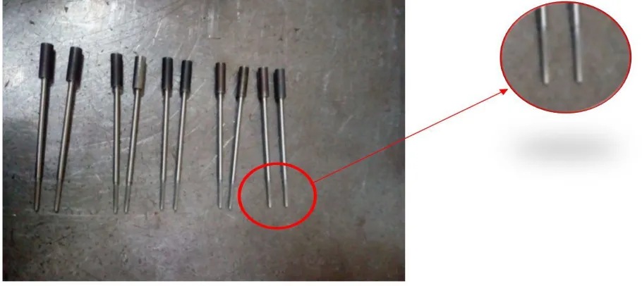
[image:1.595.77.532.535.738.2]During high pressure die casting (HPDC) of aluminium alloys there is a tendency for the molten alloy to react with the tool steel die, core pins and inserts. This reaction is commonly referred to as ‘soldering’ and involves diffusion and the formation of inter-metallic phases. It is a concern to high pressure die casters because of down-time due to regular removal of the soldering, reduced tool life and degradation of product quality. The defects are mostly due to uncontrolled process and lacunas in tool design. In concerned study, core pin failure defect is observed in the die casting process.
749
©IJRASET: All Rights are Reserved
Fig 2: Quantity of core pins failed in month
Contribution of core pin failure to rejection in corresponding months was more. Figure2, shows core pin failure for four months.
II. LITERATUREREVIEW
A. Santosh. S. Dabhole, Chaitanya. A. Kurundwad, Sujit. R. Prajapati - Process Capability Analysis of High Pressure Die Casting Process for Cap Manufacturing [1]–
The purpose of this work is to analyse capability of H.P.D.C. process to manufacture die casted product by using statistical tools. The authors used process capability analysis as a tool to find the capable process for reducing the defects occurred in H.P.D.C process like porosity, blow holes, non-filling. Process capability is the ability of process to manufacture parts within the standard limits .Process capability is technique applied in many stages of product lifecycle helps to determine capability of process to produce components within upper and lower tolerance limits. Process capability is long term performance of process once it is brought under statistical control. Process capability is method of analysing process with the help of statistical tools such as control charts, histogram, etc. developed from normal curve with good engineering judgment. Process capability is analysed by determining values of process capability indices such as process potential index (Cp), process performance index (Cpk). Cp is capability index
which considers overall process variations with respect to specified designed tolerance. For this work, the input data was directly obtained by die casting machine setup.
The work is based on following steps :
1) Assumption in process capability analysis
2) Process capability determination
3) Some thumb rules for checking capability of process
a) If Cp>1; process is capable to produce parts
b) If Cp=1; process is barely capable to produce parts
c) If Cp<1; process is not capable to produce parts
4) Some additional rules
a) If 1<Cpk< 1.33, then process is adequate .
b) If Cp>1. 66, process used is very satisfactory.
c) If Cp=Cpk, process is out of control.
In this paper work a study was conducted on the die casting components for analysing the process capability. A trial of 100 die casting shots was taken with 100 readings of different parameters.
TABLE I
Working temperature and pressure Casting pressure
(kg/cm^2)
Feed metal temperature (C)
U.S.L 850 680
750
©IJRASET: All Rights are Reserved
From these values, capability indices were calculated and complete analysis was done using MINITAB® software.
In this work numerical values for Process Capability Indices (P.C.I) were calculated for different parameters. Thus it is concluded that the process capability of the process in use for the die casting process is directly related to the defects occurring.
B. M. Khalid Imran, Syed Masood, Milan Brandt, Stefan Gulizia, Mahnaz Zahedi - Copper Based Bi-metallic Core Pin Using DMD: Industrial Evaluation [2]–
In this work a study and experiment on copper based bi-metallic core pin & comparison with tool steel core pin was performed. As tool steel core intends to fail due to severe soldering. This failure particularly suggested that the die holding time was not long enough for the casting part around the core pin to be solidified completely. Thus experiments were done using the bi-metallic core pin to reduce this failure.
The experiment was performed at the following conditions :
a) Extreme operating conditions of injection speed (50-55 m/s)
b) Holding pressure (70-75 MPa)
c) Die holding time (30s).
Aluminum alloy was used as casting material and the melt temperature was maintained at 680°C in the crucible. Two sets of core pins were prepared for HPDC. One core was made from tool steel & another one was from copper alloy. Each of the four core pins was designed for fifty HPDC shots. During trials made, the tool steel core pin however survived thirty five HPDC shots and soldering on it started after just 10 shots, while soldering on the bi-metallic core pin was observed after 35 shots and survived till 50 shots. Tool steel core pins did not survived the proposed no. of HPDC shots & resulted in failure due to soldering. Bi-metallic core pins operated without any failure up to the designed number of shots. Bi-metallic core pins facilitated quick solidification of casting material thus reduced the rate of soldering.
C. M. Suguru. Takeda, Norio. Shinmura, Shinji. Sannakanishi - Stress Analysis of Thin Wall Core Pin in Aluminum Alloy High Pressure Die Casting [3] –
In this work the study related to the heat flow pattern from casting area to core pin under different conditions and developed an efficient cooling system. It provides the information about the development of thin wall core pin shape from the perspective of heat flow and mechanicals of core pin. The problems such as soldering of core pin due to insufficient cooling, leakage, etc. arises. The authors have studied the heat flow pattern and surface temperature of core pins by using direct measurement techniques in order to reduce the inherent problems of aluminium die castings. Experiments done to optimize and verify the shape of thin wall core pins by CAE, considering the mechanicals of core pins, the virtual experiment was carried out, using ABAQUS simulation software. The core pin was made of alloy tool steel with heat treatment that was hardened up to HRC 47. Material data used in the computation is shown in Table II.
TABLE II Properties of material used in experiment Material DAC(SKD16)
1. Young’s modulus 206 GPa 2. Poisson’s ratio 0.25
In actual operation, core pins should be maintained and replaced between and shots, die releasing force also affect the core pin stress. If there is no soldering on the core pin, the die releasing force is given by equation below.
F = 2 × a × l × μ × Y × ln(b/a) Where,
Y= young’s modulus.
μ= Poisson’s ratio. a= Diameter of pin. b= Length of pin.
751
©IJRASET: All Rights are Reserved
increases the possibility of core pin failure. The above situation can be eliminated by using hollow core pins and by flowing an appropriate amount of high pressure water to efficiently remove heat so that the core pin surface temperature will drop below the solidus temperature quickly. The total stress values become lower providing better pin life.
D. Santosh. S. Dabhole, Anu. Raje, Sonal. Khandave, Pavankumar. Ghule, Akash. Shinde- Review on Implementation of Six Sigma for Controlling Defects [4]–
This work presents how the six sigma technique is used to identify the cause and defect produced and also helped to minimize the defects. The manufacturing industry under consideration was observed with high defect formation which caused increased cycle time and material loss to the industry.
In this the six sigma and the Define-Measure-Analyse-Improve-Control (DMAIC) approach is used to solve the problem. Six sigma is a disciplined process that helps to focuses on developing and delivering near-perfect products and services. It is the most widely applied technique. The Six Sigma methodology involves DMAIC phases.
Tools and techniques used in different phases of the framework are :
1) Define Phase
a) Affinity diagram.
b) Plan-Do-Check-Act (PDCA)cycle.
2) Measure Phase
a) Pareto chart
b) Process capability
c) Histogram
3) Analyze Phase
a) Cause and effect diagram b) Scatter diagram
4) Improve Phase
a) Tree diagram
b) Failure mode effect analysis
5) Control Phase
a) Standard operation procedure
b) Statistical process control
Pareto chart for component was drawn on the basis of data check sheet that described the occurrence of defects on weekly basis. By using the six sigma tools and techniques the increase in performance and decreased process variation lead to the reduction of defects, reduction of material wastage and thus improving the profit. Also the work was done on reducing the cycle time in a manufacturing firm.
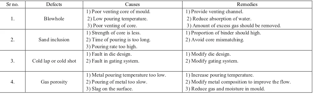
E. Vaibhav Ingle, Madhukar Sorte- Defects, Root Causes in Casting Process and Their Remedies: Review [5]-
[image:4.595.37.561.592.749.2]In this work the authors describes various casting defects their causes and their remedies, which are further described in table III.
TABLE III various casting defects their causes and their remedies
Sr no. Defects Causes Remedies
1. Blowhole
1) Poor venting core of mould. 2) Low pouring temperature. 3) Poor venting of core.
1) Provide venting channel. 2) Reduce absorption of water.
3) Amount of excess gas should be removed.
2. Sand inclusion
1) Strength of core is less. 2) Time of pouring is too long. 3) Pouring rate too high.
1) Proportion of binder should high. 2) Avoid core mismatching.
3. Cold lap or cold shot
1) Fault in die design. 2) Fault in gating system.
1) Modify die design. 2) Modify gating system.
4. Gas porosity
1) Metal pouring temperature too low. 2) Pouring of metal too slow. 3) Slag on the surface.
1) Increase pouring temperature.
752
©IJRASET: All Rights are Reserved
Fig 3: Cause and effect diagram for pin failure
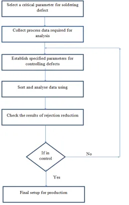
III.METHODOLOGY
The purpose of this work is to determine the root cause of failure due to soldering and to analyse the various process parameters. Following figure shows the steps followed in analysing the root cause of failure.
[image:5.595.177.436.320.730.2]753
©IJRASET: All Rights are Reserved
IV.CONCLUSION
In this work various literature about process parameters in high pressure die casting process was reviewed and presented. Thus by analysing those work it can be concluded that various process parameters or tools such as six sigma, process capability index, die casting temperature, die casting pressure must be maintained under designed value to minimize the core pin failure rate. Also some other factors such as using bi-metallic alloy and surface treatment of core pins tends to reduce the rate of core pin failure up to a remarkable limits.
REFERENCES
[1] Santosh. S. Dabhole, Chaitanya. A. Kurundwad, Sujit. R. Prajapati, “Process Capability Analysis of High Pressure Die Casting Process for Cap Manufacturing,” IJRASET,2017.
[2] M. Khalid Imran, Syed Masood, Milan Brandt, Stefan Gulizia, Mahnaz Zahedi, “Copper Based Bi-metallic Core Pin Using DMD: Industrial Evaluation,”
IJASEIT, 2012.
[3] M. Suguru. Takeda, Norio. Shinmura, Shinji. Sannakanishi, “Stress Analysis of Thin Wall Core Pin in Aluminum Alloy High Pressure Die Casting,” 2016. [4] Santosh. S. Dabhole, Anu. Raje, Sonal. Khandave, Pavankumar. Ghule, Akash. Shinde, “Review on Implementation of Six Sigma for Controlling Defects,”
IJRASET,2017.