Experimental and Comparison Study of Heat
Transfer Characteristics of Wickless Heat Pipes by
using Various Heat Inputs
N. Mukilarasan1, M. Varistus Anto Romilton2, S Ismath3, I. Venkatraman4, R Vignesh5 1
Assistant Professor, 2,3,4,5Students , Mechanical Engineering, Jeppiaar SRR Engineering College, Padur, Chennai – 603 103, Tamil Nadu,
Abstract: A wickless heat pipe is a heat transfer device which combines the principles of both thermal conductivity and phase transition without the usage of wick structure. The heat pipe generally consists of three sections namely evaporator section, adiabatic section and condensation section. An apparatus set up consisting of four heat pipes made up of different materials namely Copper, Aluminium, Brass and Stainless steel along with heater and cooling duct was designed and fabricated. Various working fluids such as Acetone, Toluene, Ethanol and Dichloro methane are used to determine which among the above working fluids can be used efficiently in heat pipes to improve its performance. The heat inputs are varied from 80 W to 460 W to determine the efficient heat input for the heat pipes. Thus the experiment was carried out to study the thermal efficiency of the heat pipes by using different materials, different working fluids and different heat inputs. At the end of the experiments, copper was found to be the material with high thermal conductivity when compared to the other materials. Dichloromethane was found to be one of the most efficient working fluid to be used in heat pipes at the heat input range of 160 W.
Keywords: Heat pipe, heat transfer characteristics, working fluid inventory
I. INTRODUCTION
Heat pipe is a heat transfer device which transports large quantities of heat with minimum temperature gradient without any additional power between the two temperature limits. It consists of three different sections namely evaporator, adiabatic section and condenser section. These three parts have equal importance and can significantly affect the performance of a heat pipe [1]. The heat input is added to the evaporator section of the container, the working fluid present in the wicking structure which is kept in the container is heated until it vaporizes. Since the latent heat of evaporation is large, considerable quantities of heat can be transported with a very small temperature difference from end to end. Thus, the structure will also have a high effective thermal conductance. The high temperature and corresponding high pressure in the evaporator section cause the vapour to flow to the cooler condenser section, where the vapour condenses and releases its latent heat of vaporization. The capillary forces existing in the wicking structure then pump the liquid back to the evaporator [2]. The evaporator and condenser sections of a heat pipe function independently, needing only common liquid and vapour streams.
A mathematical model and its numeric solution for the laminar two-phase flow of liquid and vapor of working fluid in the capillary structure of micro heat pipes was investigated by Garcia et al. [3]. The mathematical model is formulated for steady state, one-dimensional flow for the vapor and quasi-one one-dimensional flow for the liquid. The relation between the maximum heat transfer capacity and the capillary pressure is analyzed. To verify the mathematical models, the results obtained are compared with data reported in the specialized literature.
the capillary limit among operating limits of a heat pipe. The selection of the proper heat pipe cooling solution is dependent upon the developer’s specifications, design constraints and budget [8].
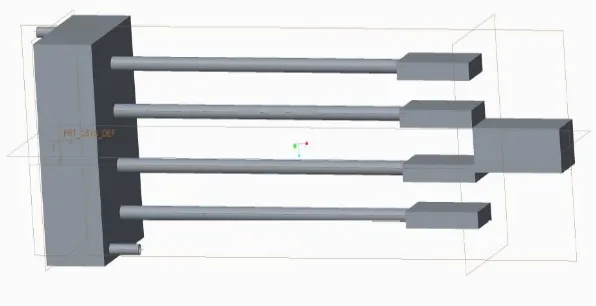
[image:2.612.158.456.159.312.2]Hence it is understood clearly that the performance of heat pipes vary depending upon the pipe materials, working fluids and heat inputs.
Figure 1 Schematic arrangement of experimental setup
II. DESIGN PARAMETERS
Outer diameter of pipe = 32 mm Inner diameter of pipe = 29 mm Thickness of pipe = 1.5 mm
Working fluids = Ethanol, Acetone, Toluene and Di chloro methane Pipe materials= Copper, Aluminium, Brass and Stainless steel Evaporator length = 100 mm
Condenser length = 100 mm Adiabatic length = 800 mm Cooling water temperature = 32o C Quantity of working fluid filled = 10 ml
III. EXPERIMENTAL PROCEDURE
The heat pipe generally consists of three sections namely, evaporating section, adiabatic section and condensation section. There are four RTDs in each pipes. One in the evaporating section, one in the condensation section and two in the adiabatic section. Thus the temperatures in the various sections of the pipes can be determined. In the evaporating section, band heaters are used to convert the working fluids into vapour. In the condensation section, water flow is used as the method to condensate the vapour into liquid. The rate of flow of water in the cooling duct is calculated. Also, the temperatures of the coolant at entry and exit are found out to determine the amount of heat transferred from the pipe to the cooling duct.
The band heaters are connected in parallel to supply same amount of heat supply with help of auto transformer. Ammeter and Voltmeter are used to calculate the amount of heat input to the pipes. The auto transformer is used to alter the voltage. Thus the required amount of voltage can be supplied.
Figure 2 Experimental setup
IV. MATHEMATICAL EQUATIONS USED
Effectiveness of the heat pipe is indirectlybrought in terms of thermal resistance
R= °C/W --- (1)
And the overall heat transfer co-efficient is given by h= W/m2 °C --- (2)
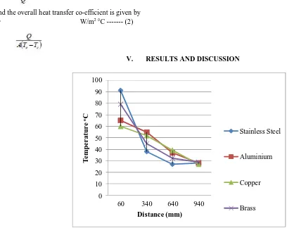
V. RESULTS AND DISCUSSION
Fig. 3: Axial temperature profile of Ethanol at 80 W 0
10 20 30 40 50 60 70 80 90 100
60 340 640 940
T
e
m
p
e
r
a
tu
r
e
oC
Distance (mm)
Stainless Steel
Aluminium
Copper
[image:3.612.50.458.387.711.2]0 10 20 30 40 50 60 70 80
60 340 640 940
Te
m
p
e
r
atu
r
e
oC
Distance (mm)
Stainless Steel
Aluminium
Copper
Brass
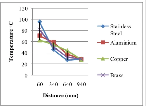
[image:4.612.182.433.79.256.2]Fig. 4 Axial temperature profile of Ethanol at 108 W
0 20 40 60 80 100 120
60 340 640 940
T
e
m
p
er
a
tu
re
oC
Distance (mm)
Sta inless Steel
Aluminium
Copper
[image:4.612.183.433.288.470.2]Bra ss
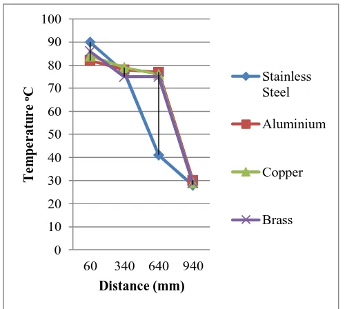
Fig. 5: Axial temperature profile of Ethanol at 140 W
0 20 40 60 80 100 120
60 340 640 940
T
e
m
p
e
r
a
tu
r
e
oC
Distance (mm)
Stainless Steel
Aluminium
Copper
Brass
[image:4.612.183.430.501.711.2]0 20 40 60 80 100
60 340 640 940
T
e
m
p
e
r
a
tu
r
e
oC
Distance (mm)
Sta inless Steel
Aluminium
Copper
Bra ss
Fig. 7 Axial temperature profile of Ethanol at 416 W
0 10 20 30 40 50 60
60 340 640 940
T
e
m
p
e
r
a
tu
r
e
oC
Distance (mm)
Sta inless Steel
Aluminium
Copper
Bra ss
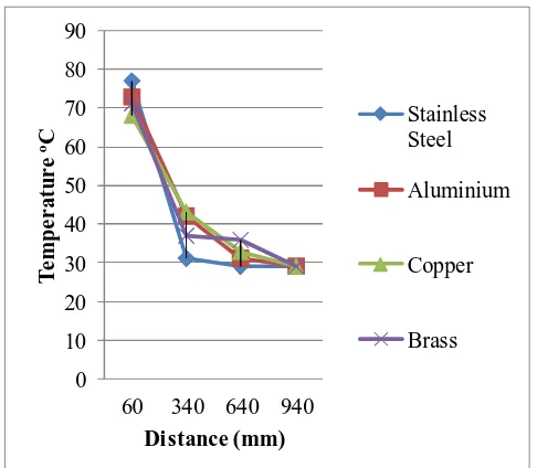
[image:5.612.182.432.493.717.2]Fig. 8 Axial temperature profile of Dichloromethane at 80 W
0 10 20 30 40 50 60 70 80 90 100
60 340 640 940
Te
m
p
e
r
atu
r
e
oC
Distance (mm)
Stainless Steel
Aluminium
Copper
Brass
0 10 20 30 40 50 60 70 80
60 340 640 940
T
e
m
p
e
r
a
tu
r
e
oC
Distance (mm)
Stainless Steel
Aluminium
Copper
[image:6.612.185.428.78.290.2]Brass
Fig. 10: Axial temperature profile of Dichloromethane at 140 W
0 10 20 30 40 50 60 70 80 90 100
60 340 640 940
T
e
m
p
e
r
a
tu
r
e
oC
Distance (mm)
Stainless Steel
Aluminium
Copper
Brass
Fig. 11: Axial temperature profile of Dichloromethane at 165 W
0 10 20 30 40 50 60
60 340 640 940
T
e
m
p
e
r
a
tu
r
e
oC
Distance (mm)
Stainless Steel Aluminium
Copper
Brass
0 10 20 30 40 50 60 70
60 340 640 940
T
e
m
p
e
r
a
tu
r
e
oC
Distance (mm)
Sta inless Steel
Aluminium
Copper
Bra ss
[image:7.612.185.428.78.252.2]Fig. 13: Axial temperature profile of Acetone at 80 W
0 10 20 30 40 50 60 70 80 90
60 340 640 940
T
e
m
p
e
r
a
tu
r
e
oC
Distance (mm)
Stainless Steel
Aluminium
Copper
[image:7.612.188.426.288.503.2]Brass
Fig. 14: Axial temperature profile of Acetone at 108 W
0 10 20 30 40 50 60 70 80 90
60 340 640 940
T
e
m
p
e
r
a
tu
r
e
oC
Distance (mm)
Stainless Steel
Aluminium
Copper
Brass
0 20 40 60 80 100
60 340 640 940
T
e
m
p
e
r
a
tu
r
e
oC
Distance (mm)
Stainless Steel
Aluminium
Copper
[image:8.612.182.430.79.290.2]Brass
Fig. 16: Axial temperature profile of Acetone at 209 W
0 10 20 30 40 50 60 70 80 90
60 340 640 940
T
e
m
p
e
r
a
tu
r
e
oC
Distance (mm)
Stainless Steel
Aluminium
Copper
Brass
[image:8.612.182.430.326.519.2]Fig. 17: Axial temperature profile of Acetone at 448 W
0 20 40 60 80 100 120
60 340 640 940
T
e
m
p
e
r
a
tu
r
e
oC
Distance (mm)
Stainless Steel Aluminium
Copper
Brass
[image:8.612.186.429.556.712.2]0 20 40 60 80 100 120 140
60 340 640 940
Te
m
p
e
r
atu
r
e
oC
Distance (mm)
Stainless Steel
Aluminium
Copper
Brass
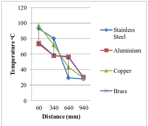
[image:9.612.186.427.78.250.2]Fig.19: Axial temperature profile of Toluene at 476 W
0 20 40 60 80 100 120 140 160
60 340 640 940
Te
m
p
e
r
atu
r
e
oC
Distance (mm)
Stainless Steel
Aluminium
Copper
[image:9.612.187.425.491.699.2]Brass
Fig. 20: Axial temperature profile of Toluene at 540 W
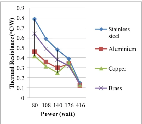
0 0.1 0.2 0.3 0.4 0.5 0.6 0.7 0.8 0.9
80 108 140 176 416
T
h
e
r
m
a
l
R
e
si
st
a
n
c
e
(
oC
/W
)
Power (watt)
Stainless steel
Aluminium
Copper
Brass
0 0.05 0.1 0.15 0.2 0.25 0.3 0.35 0.4
80 108 140 165 416
Th
e
r
m
al
R
e
si
stan
c
e
(
oC
/W
Power (watt)
Stainless steel
Aluminium
Copper
Brass
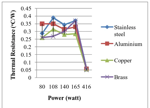
Fig. 22: Variation of thermal resistance with different heat inputs while using Dichloromethane as working fluid
0 0.1 0.2 0.3 0.4 0.5
80 108 150 209 448
T
h
e
r
m
a
l
R
e
si
st
a
n
c
e
(
oC
/W
)
Power (watt)
Sta inless steel
Aluminium
Copper
Bra ss
Fig. 23 Variation of thermal resistance with different heat inputs while using Acetone as working fluid
0.17 0.175 0.18 0.185 0.19 0.195 0.2
416 476 540
T
h
e
r
m
a
l
R
e
si
st
a
n
c
e
(
oC
/W
)
Power (watt)
Stainless steel
Aluminium
Copper
Brass
[image:10.612.181.432.78.259.2]
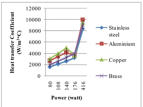
0 2000 4000 6000 8000 10000 12000 8 0 1 0 8 1 4 0 1 7 6 4 1 6 H e a t tr a n sf e r C o e ff ic ie n t (W /m 2 oC ) Power (watt) Sta inless steel Aluminium Copper Bra ss
Fig. 25: Variation of heat transfer coefficient with different heat inputs while using Ethanol as working fluid
0 5000 10000 15000 20000 25000 30000 8 0 1 0 8 1 4 0 1 6 5 4 1 6 H e a t tr a n sf e r C o ef fi c ie n t (W /m 2 oC ) Power (watt) Sta inless steel Aluminium Copper Bra ss
Fig. 26: Variation of heat transfer coefficient with different heat inputs while using Dichloromethane as working fluid
0 2000 4000 6000 8000 10000 12000 14000 16000 18000
80 108 140 165 416
H e a t tr a n sf e r C o e ff ic ie n t (W /m 2 oC ) Power (watt) Stainless steel Aluminium Copper Brass
5800 6000 6200 6400 6600 6800 7000
416 476 540
H
e
a
t
tr
a
n
sf
e
r
C
o
e
ff
ic
ie
n
(W
/m
2
oC
)
Power (watt)
Sta inless steel
Aluminium
Copper
Bra ss
[image:12.612.182.429.80.272.2]
Fig. 28: Variation of heat transfer coefficient with different heat inputs while using Toluene as working fluid
VI. CONCLUSION
A setup consisting of four heat pipes made up of different materials has been successfully developed, fabricated and tested. Different operating characteristics are presented at different heat inputs from 80 W to 460 W. From the
investigation, the following findings are obtained:
A. The overall heat transfer coefficient of heat pipe increases with increase in heat input, in the range of inputs tested for Dichloromethane.
B. The pipe made up of copper shows better characteristics when compared to other materials.
C. The heat input of 160 V is proved to be the heat input where the heat pipe can work efficiently.
D. Aluminium is found to be the effective heat pipe while using Ethanol and Dichloromethane as the working fluids.
E. Brass is found to be the effective heat pipe while using Acetone as the working fluid.
F. Copper is found to be the effective heat pipe while using Toluene as the working fluid.
REFERENCES
[1] Senthilkumar R, Vaidyanathan S, Sivaraman B 2011, “Effect of Inclination Angle in Heat Pipe Performance Using Copper Nanofluid” Procedia Engineering 3715 – 372
[2] Tourniera, J. M. and El-Genka, M. S., March 1994, “A heat pipe transient analysis model”, International Journal of Heat and Mass Transfer, Volume 37, Issue 5, pp. 753-76
[3] Garcia, F., Segura, J. and Zarea, S. June 2000 “Thermal fluid dynamic steady state behavior of micro heat pipes”, Universidad, Ciencia y Tecnologia, Vol. 4, no. 14, pp. 59-6
[4] R.A. Hossain, M.A.K Chowdhuri, C. M. Feroz, 2011 “Design, Fabrication and Experimental Study of Heat Transfer” Jordan Journal of Mechanical and Industrial Engineering ,volume 4, Pages 531- 54
[5] J. M. Ha and G. P. Peterson, “The Heat Transport Capacity of Micro Heat Pipes”, J. Heat Transfer, November 1998, Volume 120, Issue 4, 1064 (8 pages) doi:10.1115/1.282589
[6] Senthilkumar R, Vaidyanathan S, Sivaraman B, 2011, “Performance Analysis of Heat Pipe Using Copper Nanofluid with Aqueous Solution of n-Butanol”, International Journal of Mechanical, Aerospace, Industrial, Mechatronic and Manufacturing Engineering, Vol:5, No:2, 201
[7] Dunn, P. and Reay, D.A., 1982, Heat Pipes, Pergamon Press New York, Third Editio