Corresponding Author: A. Semmah, Department of electrical engineering, Djillali Liabes University, Sidi Bel Abbès, Algeria.
297
the line current and improve the power factor. The DPC principle is based on the control of instantaneous active and reactive powers. The principal idea of DPC was suggested initially by Ohnishi (1991) and developed then by Noguchi and Takahachi in 1998. This concept is similar to DTC applied to induction motors. With the aim of ensuring a stable active power exchange, a fuzzy inference system is adopted for the DC voltage control. A digital simulation, in Matlab/Simulink/ SimPowerSystems and Fuzzy Logic Toolbox, was carried out and given in the end of this paper. Simulation results show clearly the effectiveness of the of the adopted control strategies.
Key words: PWM rectifier, direct power control, voltage, estimation, instantaneous active and reactive powers, fuzzy control.
INTRODUCTION
The actual development in power electronics made that static converters are used in several industrial fields. But these devices represent nonlinear loads, which absorb a no sinusoidal current and behave like harmonics generators. Moreover, they consume sometimes reactive energy. Consequently, the wave shape of the source current loses its sinusoidal form and one also obtains a degradation of the power-factor. By this fact, electric power distributors are thus seen obliged to impose standards and to protect themselves from these disturbances.
Several control strategies were proposed in recent works for the PWM rectifier (Azizi, H.; Malinowski, M., 2003; Kazmierkowski, M.P., 1998). Although they can achieve the same total goal, such as a high power factor and sinusoidal current, but their principles differ. Particularly, the voltage orientation control (VOC) and virtual flux orientation control (VFOC), can guarantee a high dynamics and static performances by internal loops of current control (Kazmierkowski, M.P., 1998; Malinowski, M., 2001; Jian, Kang Yong, 1999). These control strategies became very popular and consequently they are developed and improved. Final configuration and performances of the VOC techniquedepend largely on the quality of the current control strategy.
Another approach is based on instantaneous direct active and reactive power control, and is called direct power control (DPC). Proper switching states are selected for next switching table, based on hysteresis controllers’ outputs and the position of the line voltage space vector. However, high sampling frequency requirement is a main drawback of the switching table based direct power control scheme (Malinowski, M., 2001).
The first developed application of direct control was the stator flow control and the electromagnetic torque of an electric machine without any modulation block. Such structure was called Direct Torque Control,DTC. (Manninen, V.; Attaianese, C.,). Then, Direct Power Control (DPC) was inspired from DTC and was proposed in (Noguchi, T., 1998). In 2001, DPC was developed in (Malinowski, M., 2001) for controlling rectifiers connected to the network. In this case, active and reactive instantaneous powers represent the controlled variables. DPCand VF-DPC are based on instantaneous control active and reactive powers (Malinowski, M., 2001). In this control technique internal currents control loops and modulation block are eliminated.
In this case, logical states of PWM rectifier are generated from a switching table based on instantaneous errors between estimated active and reactive powers and theirs reference values. These new techniques allow controlling the PWM rectifier without network voltages sensors.
The active power exchange must be stable by insuring a DC voltage equal to its reference so that the PWM rectifier operates with a good efficiency. This can be carried out by using a control system able to regulate DC voltage.
298 Fig. 1: General diagram of th PWM rectifier.
II. PMW Rectifier Structure:
The power circuit of the PWM rectifier contains a bridge of six power transistors with anti-parallel diodes, which is used to carry out the PWM generation as well as the power bidirectional conversion.
The converter is supplied by a voltage source in series with an inductance and a resistance, which model the network.
Generally, the network inductance is insufficient. To attenuate the ripples due to the switching operation of the PWM rectifier, a series filter having a more significant inductance is needed.
A load and a capacity are connected simultaneously at the output of the converter. The capacity is used as a voltage source and allows the rectifier to also operate as an inverter.
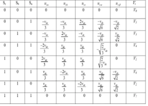
Logical states impose rectifier input voltages and check:
(1)
Thus the operation principle of the rectifier is illustrated by the following matrix system:
(2) The AC side can be modeled by the following equations:
(3)
AC currents ia, ib and ic are generated by voltage drops at impedances network boundaries (ea-uca), (eb-ucb)
and (ec-ucc), and then these currents will be cut out through the switches to provide the D.C. current idc such as:
(4)
299
The vector representation of voltage vectors generated by the rectifier is illustrated in fig.2:
Fig. 2: Voltage vectors generated by the rectifier.
III. DPC Strategy
DPC principle is based on a control vector selection according to a switching table found on the digitized errors Sp, Sqof instantaneous active and reactive powers, provided by two level hysteresis regulators, as well as
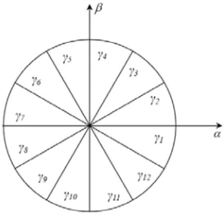
on angular position of the estimated voltage vector. According to this position value, the plan (α -β) is divided into twelve sectors where one must associate at each sector a logical state of the rectifier. The reference of the active power is reactive power reference is chosen equal to zero. Hence the key point for implementing DPC strategies is a correct and a fast estimation of active and reactive line powers.
The estimation of instantaneous active and reactive powers is carried out by:
(5)
(6)
The line voltage can be estimated by the following equation:
(7)
300 Fig. 3: α-β plant divided into 12 sectors.
The outputs hysteresis regulators given by the boolean variables Spand Sq, indicate higher or lower limits of
powers errors according to the below logic:
(8)
Where hp, hqare the variations of the hysteresis regulators.
By neglecting line voltage variations (Bouafia, A., 2009; Chaoui, A., 2008), dynamics of active and reactive powers can be given as follows:
(9)
(10)
Logical states of the rectifier switches are generated basing on the switching table given as below:
Table 2: Switching table.
IV. Fuzzy DC Voltage Control
The goal of a DC side control system is to regulate DC voltage and to generate magnitude of the reference line current witch will be multiplied by the dc voltage to obtain the reference of the instantaneous active power. To have unity power factor condition, reference reactive power must be equal to zero.
The regulation function is ensured by a PI corrector shown in the figure below:
301 Fig. 5: Membership functions of input and output variables.
NB: Negative Big; NM: Negative Medium; NS: Negative Small; ZE: Zero; PB: Positive Big; PM: Positive Medium; PS: Positive Small;
Fuzzy rules are gathered in an inference matrix shown in Table.3:
Table 3: Inference table of the DC voltage fuzzy controller.
V. Simulation and Discussion:
To validate the effectiveness of the control strategy studied in this paper, a digital simulation was carried out under MATLAB/SIMULINK environment.
The DC voltage control system is tested as well as the DPC method following a DC voltage step variation occurred at t=0.5s from 380V to 470V.
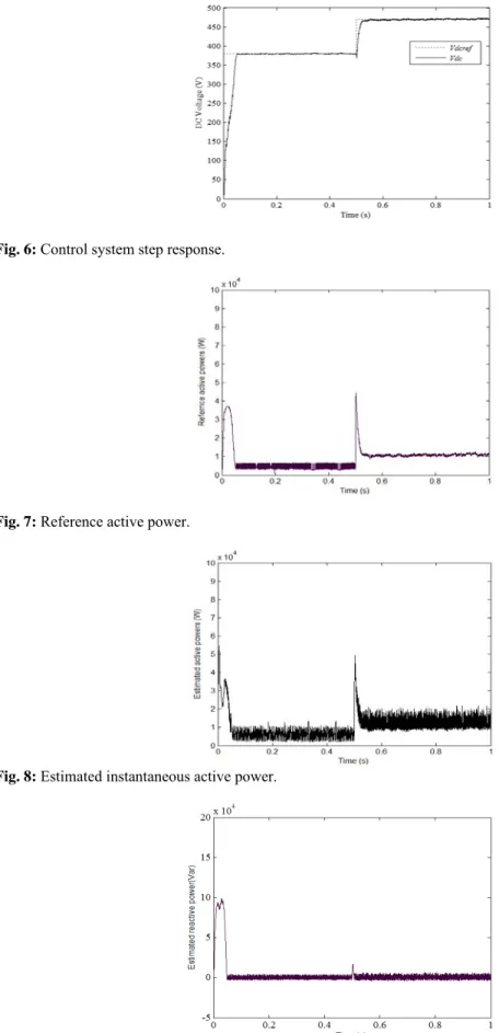
The effectiveness of the DC voltage fuzzy control is illustrated by fig.6. We can see that the system became stable and robust. The system response is very fast, and does not present any overshoot
Fig.8 shows that when the DC voltage reaches the new reference value, the active power and consequently the line current increase. In this case the power increase is limited, what avoids dangerous overcurrents for the system operation.
In fig. 9, we can see that the reactive power flow is small, what is very beneficial for the system performances.
The line voltage and current are almost in phase (see fig.10), and thus the power-factor is almost equal to 1. The wave shape of the line current close to the sinusoid, and hence the THD (Total Harmonic Distortion) was reduced.
302 Fig. 6: Control system step response.
Fig. 7: Reference active power.
Fig. 8: Estimated instantaneous active power.
303 Fig. 10: Sinusoidal line current in phase with the line voltage.
VI. Conclusion:
In this article we presented a new control strategy for a PWM rectifier. It concerns the use of the direct power control principle via a fuzzy control system on the DC side, it reduces the number of sensors used, and to offer a fast power response following a disturbance. In order to obtain a stable exchange of the active power flow between the converter and the electrical network, the dc voltage is controlled using a fuzzy regulator. Simulation results showed that the DPC technique combined to a dc voltage fuzzy control improves the system performances.
These improvements affect the performances of the system response on the DC side (overshoot and response time), as well as the power-factor and the THD of the line current.
APPENDICE - System parameters
R=88m, L=3.127mH, C=1mF, Rload=100, Vdcref=380V ,Peak amplitude of line voltage=200V, Source voltage
frequency=50Hz.
REFERENCES
Attaianese, C., G. Tomasso, A. Damiano, I. Marongiu, A. Perfetto, "Direct Torque and Flux Control of Induction Motor Drives", PEDS’97, Singapore.
Azizi, H., A. Vahedi, "Performance Analysis of Direct Power Controlled PWM Rectifier under Disturbed AC Line Voltage", ICREPQ’05, Zaragoza- Spain.
Bouafia, A., F. Krim, J.P. Gaubert, 2009. "Design and implementation of high performance direct power control of three-phase PWM rectifier, via fuzzy and PI controller for output voltage regulation", Energy Convers Manage, 50(1): 6-13.
Chaoui, A., F. Krim, J.P. Gaubert, L. Rambault, 2008. "DPC controlled three-phase active filter for power quality improvement", Int J Electric Power Energy Syst., 30(8): 476-85.
Jian, Kang Yong, Duan Shan Xu, Zhang Kai, Chen Jian, 1999. "Simplified control circuit of three phase PWM rectifier", Applied Power Electronics Conference and Exposition, APEC ' 99(1): 229 -233.
Kazmierkowski, M.P., L. Malesani, 1998. "Current control techniques for three-phase voltage-source PWM converter: a survey", IEEE Trans Ind Electron, 45: 691-703.
Malinowski, M., M.P. Kazmierkowski, S. Hansen, F. Blaabjerg, G.D. Maeques, 2001. "Virtual flux based direct power control of three phase PWM rectifiers", IEEE Trans Ind Appl., 37: 1019-1027.
Malinowski, M., M.P. Kazmierkowski, Trzynadlowski, 2003. "A. Review and comparative study of control techniques for three-phase PWM rectifiers", Mathematics and Computers in Simulation, 63(17): 349-361.
Manninen, V., "Application of Direct Torque Control Modulation Technology to a Line Converter", EPE’95: 1292-1296, Sevilla, Spain.