Sanju Kumbar, Dr. S. Ranganath IJSRE Volume 4 Issue 12 December 2016 Page 6099
Volume||4||Issue||12||December-2016||Pages-6099-6107||ISSN(e):2321-7545 Website: http://ijsae.in
DOI: http://dx.doi.org/10.18535/ijsre/v4i12.05
Effect of Tantalum Carbide (Tac) Coating on Performance of Rolling Element in Ball
Bearing: An Experimental Study Using Four Ball Test Rig
Authors
Sanju Kumbar1, Dr. S. Ranganath2 1
M.E. Student, Dept. of mechanical engineering,UVCE,Bangaluru 2
Professor, Dept. of mechanical engineering,UVCE,Bangaluru Email: [email protected]
ABSTRACT:
The performance of rolling elements in ball bearings is a very important parameter from the point of reliability and durability of machines. The advances in aeronautical engineering demands more reliable and long lasting motors which have to be design for very high speed. The literature indicates atoms of different people aiming at improving the performance of roller bearing. The literature highlights that giving coating to ball element is a very potential method of improving the performance of bearings.
In the present investigation the High Carbon High Chromium [HCHCr] balls were coated with Tantalum Carbide [TaC] and experiments were conducted employing “Four Ball Test Rig”. The test rig simulates the field conditions in the bearing. The system was lubricated with SAE 20w40 oil, the experiments were conducted at an ambient temperature of 75±2 o C and speed was maintained at 1200 rpm. The state of stress was monitored by loading 100N, 300N and 500N by loading pan. The contact area of both upper and lower balls was studied in Scanning Electron Microscope for identifying the deformation and damage mechanisms. The test results indicated that the coefficient of friction was found to be correspondingly very from 0.25, 0.12 and 0.12 as load increased from 100N, 300N and 500N. The coefficient of friction was found to decreased and stabilized as load increased. The microscopic study reveals that the deformations were more uniform as load increased.
Keywords: Contact Stresses, Surface Deformation, Surface Coating, Tantalum Carbide, Four Ball Testing and Coefficient of Friction
1. INTRODUCTION
In case of non-conforming contact surface, the geometry of contact gives rise to Hertzian contact stresses. These Hertzian contact stresses are independent of external loads. The Hertzian contact stresses vary from minimum value to a large value. Since stresses varying over a large range, elastic, inelastic and fracture takes place. In addition, these stresses vary with respect to time and lead to fatigue type of loading. Lubricants are extensively used in case of ball bearings and roller bearings and other contacts. Though lubricants are used in many times, these lubricants fails and leads to dry contact. Prediction of performance of these bearings needs the knowledge of contact stresses, response to fatigue loading and characteristics of lubricants.
In practice it has been found that the ball bearings and roller bearings are found to fail due to fatigue loading. The defects like Pitting and Spalling are observed. Many researchers have tried to characterize the performance of such bearings by conducting laboratory test, such as rolling disc contact, sliding contact and rolling of ball surfaces.
Sanju Kumbar, Dr. S. Ranganath IJSRE Volume 4 Issue 12 December 2016 Page 6100 stresses are called contact stresses. This concept was first experimentally and mathematically determined by Heinrich Hertz. Hertz developed a theory to calculate the contact area and pressure between the two surfaces contact stress forms the foundation for the equations for load bearing capabilities and fatigue life in bearings, gears, and any other bodies where two surfaces are in contact. [1]
1.1 Tribology and Rolling Contact
In our daily lives we come across many manifestation of tribology. Walking on the floor, gripping anything in our hands, sliding of materials, brushing operation, motions involved in machineries, interaction between skin and clothes all involve the impact of tribology.
Tribology is the science of study in case of objects which interacts with each other. The most important factors non active frictional force and alteration of contact surface due to wear.
Friction & Wear:
Friction and wear are the factors used to quantify the effects of interaction between two contacting interfaces. The contact is established between two surfaces either to transfer force or motion. The quantified friction and wear depends on material pair, extent of loading, type of deformation and operational conditions. Friction and wear are not material properties but depends on the system. In all machineries rotational motion exists. It is also required to transfer loads between the elements which are under rolling contacts. Bearings of different types like bush bearing, roller bearing, ball bearing etc. are extensively used in case of where rolling between two rotate elements.
1.2 Coating
Coating is a covering that can be applied to the surface of an object, normally called as substrate by improving its appearance, corrosion resistant property, wear resistance, etc. Process of coating involves application of thin film of functional material to a substrate. The functional material may be metallic or non-metallic; organic or inorganic; solid, liquid or gas. The different of coatings are classified as follows.
Non-metallic coatings Wire and cable coating Planner coating
Contour coating Metallic coatings Electroplating Chrome Plating Alloy Plating
2. METHODOLOGY 2.1 Procurement of Material
Carbon Steel balls (Mild Steel) of High carbon high chromium [HCHC/HCHCr] or D2 Diameter of ball= 1/2” = 12.7 mm ± 5µ
Diameter inspection trials in mm: 12.7, 12.697, 12.696, 12.702, 12.698, 12.704, 12.700, Composition:
2% Carbon [C] 12% Chromium [Cr]
0.2 – 0.35% Silicon [Si] and Manganese [Mn] SAE 20W40 grade oil for lubrication
This is a direct hardening material and can be hardened to 58-60 HRC. 2.2 Test Conditions
The test shall be conducted under the following conditions of the four ball tester: Temperature: -75 ± 2 °C
Sanju Kumbar, Dr. S. Ranganath IJSRE Volume 4 Issue 12 December 2016 Page 6101 Duration: - 60 ± 1 min
Load: - 3 Trials
Trial 1: 10 kgf (100N) Trial 2: 30 kgf (300N) Trial 3: 50 kgf (500N) 2.3 Coating of Material
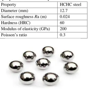
Steel balls made of high carbon high chromium steel (HCHC steel) confirming to AISI specifications are used in the static experiment. The dimension and physical properties of ball elements are shown in Table 4.1.
Table 2.1 Dimension and physical properties of test samples
Property HCHC steel
Diameter (mm) 12.7
Surface roughness Ra (m) 0.024
Hardness (HRC) 60
Modulus of elasticity (GPa) 200
Poisson’s ratio 0.3
Fig. 2.1 Mild steel (HCHCr) ball elements without coating
The above mentioned ball elements were coated with Tantalum Carbide (TaC) for investigation of this study. The coating for ball elements was given by Physical Vapor Deposition (PVD) plasma spray coating method. The coating was done at Oerilikon Blazers Coating India Pvt. Ltd, Bengaluru-560099. The characteristics of coatings are tabulated in bellow table.
Table 2.2: characteristics of coating of ball elements
Property Details
Coating material Tantalum Carbide
Micro hardness 5000 (HV 0.05)
Coating thickness range (µm)
100 microns
Maximum service
temperature
500 ºc
Coating temperature < 150 ºc
Coating color Black Rainbow
Coating structure Monolayer
Sanju Kumbar, Dr. S. Ranganath IJSRE Volume 4 Issue 12 December 2016 Page 6102 3. EXPERIMENTATION
3.1 Four Ball Test Rig
The four ball testing machine shown in 3.1 is intended for bench mounting and is carried on a steel base plate. The body of the machine is a cylindrical steel fabrication, the upper part of which carries the driving spindle, which supports the rotating test ball in a collet chunk. The spindle, which oil mist lubricated ball bearings, is driven by a flat belt from the motor which is supported by a plate on the side of the main casting.
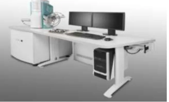
Fig. 5.1 Four Ball Test rig 3.2 Scanning Electron Microscope
Scanning Electron Microscope (SEM) is used for the micro structural investigation of the specimen with much higher resolution in conjunction with energy dispersive spectroscopy (EDS). The TESCON VEGA3 LMU is a high performance, scanning electron microscope with a high resolution of 3 nm. The low vacuum mode (which can be accessed by the click of mouse), Allows for observation of specimens which cannot be viewed at high vacuum, due to excessive water content or due to non-conductive surface. Its asynchronous 5 axis mechanically eccentric stage with comp eccentric rotation and tilt can accommodate a specimen of up to 8 inches in diameter. Standard automated features include autofocus/auto stigmator, Autogun (saturation, bias and alighnment) and automatic contrast and brightness.
Sanju Kumbar, Dr. S. Ranganath IJSRE Volume 4 Issue 12 December 2016 Page 6103 4. RESULTS AND DISCUSSION
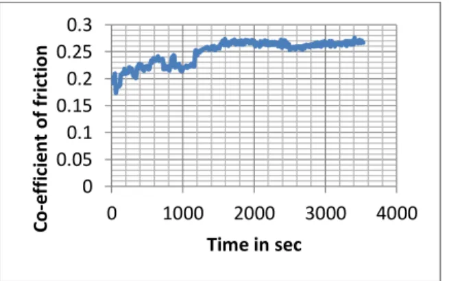
The performance of rolling elements in engineering application is demanding because of evolution of high speed engines. A systematic approach has been employed in the present investigation for understanding the role of coating materials on ball elements in roller bearing system. The Tantalum Carbide coating was given on ball elements by physical vapor deposition plasma thermal spray coating method. These coated ball elements were tested in “Four Ball Testing Rig”. The typical dependency of coefficient of friction on sliding time is shown in figures 5.1, 5.2 and 5.3
Fig. 5.1 Dependent of coefficient of friction on sliding time vs. Normal load for 100N
Fig. 5.1 shows the dependency of coefficient of friction on sliding time for normal load of 100 N. The coefficient of friction is varying from approximately 0.2 to 0.275 over a time from 0 seconds to 1500 sec. The coefficient of friction was found to be stabilized at about 0.275 after 1500 seconds.
Fig. 5.2 Dependent coefficient of friction on sliding time vs. Normal load for 300N
Fig. 5.2 shows the dependency of coefficient of friction on sliding time for normal load of 300 N. The coefficient of friction was found to be gradually increasing from 0.095 to 0.12 from 0 to 800 sec. The coefficient of friction was fond to be stabilized at about 0.12 after 800 sec.
Fig. 5.3 Dependent coefficient of friction on sliding time vs. Normal load for 500N
The Fig. 5.3 shows the dependency of coefficient of friction on sliding time for normal load of 500N. The coefficient of friction was fond to be approximately 0.12 over a period of 0 sec to 1000 sec. The coefficient of friction was found to be 0.119 which is almost equal to 0.12 after 1000 sec. This result shows the
0 0.05 0.1 0.15 0.2 0.25 0.3
0 1000 2000 3000 4000
Co -e ff ici e n t of f ri ct ion
Time in sec
0 0.05 0.1 0.15
0 1000 2000 3000 4000
Co -e ff . of f ri ct ion
Time in seconds
0.117 0.118 0.119 0.12 0.121 0.122 0.123
0 500 1000 1500 2000
Co -ef fi ci en t. o f fr ic ti o n
Sanju Kumbar, Dr. S. Ranganath IJSRE Volume 4 Issue 12 December 2016 Page 6104 coefficient of friction indicated that the average coefficient of friction was more at lower loads and stabilized as load increased.
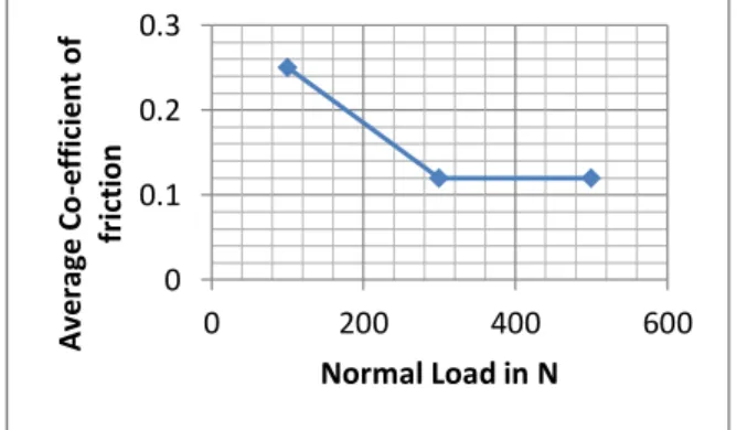
The average coefficient of friction was estimated from above graphs at different level of loadings and tabulated in table 5.1
Table 5.1: The average coefficient of friction and corresponding applied load
Applied load (in newton) N
Average Co-efficient of Friction
100 0.25
300 0.12
500 0.12
The average coefficient of friction is 0.25 at a normal load of 100N. It was found to be 0.12 when normal loads were 300N and 500N. The results of average coefficient of friction indicated that the average coefficient of friction was more at lower loads and stabilized as load increased.
The test results indicated that the coefficient of friction was found to be correspondingly very from 0.25, 0.12 and 0.12 as load increased from 100N, 300N and 500N. The coefficient of friction was found to decreased and stabilized as load increased. The microscopic study reveals that the deformations were more uniform as load increased.
The dependency of average coefficient of friction on normal load which are given in Table 5.1 are plotted and shown in Fig. 5.4 below.
Fig. 6.4 Graph of average coefficient of friction and corresponding normal load
The figure 5.4 indicates that the average coefficient of friction is getting stabilized to a constant value of 0.12 as load increased though the average coefficient of friction was 0.25 when initial load level was 100N. The scanning electronic microscopic study, for understanding the dependency of coefficient of friction on sliding distance or time of sliding was carried out. The micrographic images were taken many iterations of working depth at above 500x for clear understanding of this study.
(a) Coating: TaC, Load: 100N, Upper Ball
0 0.1 0.2 0.3
0 200 400 600
A
ve
ra
ge
C
o
-e
ff
ici
e
n
t
of
fr
ict
ion
Sanju Kumbar, Dr. S. Ranganath IJSRE Volume 4 Issue 12 December 2016 Page 6105 (b) Coating: TaC, Load: 100N, Upper Ball
Fig. 5.5 Scanning Electron Micrograph for Upper Balls at 100N Normal Load.
Fig. 5.5 (a) & (b) corresponds to scanning electron micrograph of the contact area of upper ball. The micrographs shows no peeling of coatings, but shows light grooves on the coatings.
(a) Coating: TaC, Load: 100N, Lower Ball
(b) Coating: TaC, Load: 100N, Lower Ball
Fig. 5.6 Scanning Electron Micrograph for Lower Balls at 100N Normal Load.
Fig. 5.6 (a) & (b) micrographs shows the contact area of lower ball. The micrograph shows mild grooves in coating which run horizontal in direction. These grooves are found to be more prominent when compare to grooves observed in case of contact area of upper ball.
(a) Coating: TaC, Load: 300N, Upper Ball
Sanju Kumbar, Dr. S. Ranganath IJSRE Volume 4 Issue 12 December 2016 Page 6106 Fig. 5.7 shows the contact area of upper ball. The micrograph reveals damage of coating unlike in case of 300N load, here the damages are appreciated to be verticle in direction indicating peeling possibility of coating.
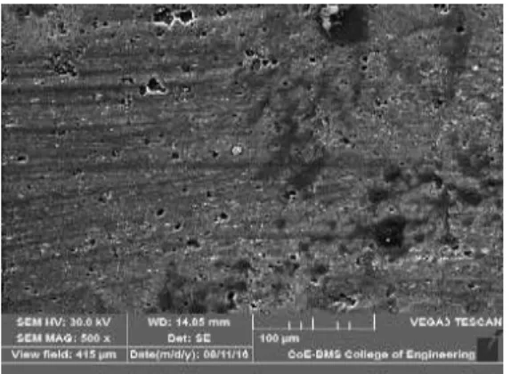
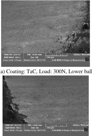
(a) Coating: TaC, Load: 300N, Lower ball
(b) Coating: TaC, Load: 300N, Lower Ball Fig. 5.8 Scanning Electron Micrograph for Lower Balls at 300N Normal Load.
Fig. 5.8 (a) & (b) shows contact area of lower balls at 300N load. The micrograph shows no grooves which suggest the deformation are more uniform and suggesting a reseason for observed low coefficient of friction at 300N.
(a) Coating: TaC, Load: 500N, Upper Ball
(b) Coating: TaC, Load: 500N, Lower Ball
Sanju Kumbar, Dr. S. Ranganath IJSRE Volume 4 Issue 12 December 2016 Page 6107 Fig 5.9 (a) shows the micrograph of contact area of upper ball and Fig. 6.9 (b) shows the micrograph of contact are of lower balls for 500N. The micrograph shows no uneven deformation. The deformation in this case appear to be not as uniform as 300N load. The micrographic features explains the observed dependency of coefficient of friction on normal load.
5. CONCLUSION
The normal load was found to influence the deformation and coefficient of friction in case of coated ball elements.
The coefficient of friction was found to be more at lower level of normal loads. The coefficient of friction was found to be stabilized as load increased.
The deformation was more uniform as load increased.
REFERENCES:
1. K. L. Johnson, (1985) “Contact Mechanics”, Cambridge University Press.
2. Farshid Sadeghi, Behrooz Jalalahmadi, Trevor S. Slack, Nihar Raje and Nagaraj K. Arakere, Journal of Tribology, ASME October 2009, Vol 131 1-15.
3. K. Thoma , L. Rohr, H Rehaman, S. Roos And J. Michler, Tribology International. 37 (2004) 463-471.
4. Waldemar Karaszewski, Tribology International, 41 (2008) 889-895. 5. W.Piekoszewski, M.Szczerek and W.Tuszynski, Wear, 249(2001) 188-193.
6. P.Zhao, M.Hadfield, Y.Wang and C.Vieillard, Wear, Vol. 257, Issue 9-10, Nov 2004, P. 1047-1057. 7. T.Lesniewski and S. Krawiec, Wear, 264 (2008) 662-670.
8. P.Clayton and D.N. Hill, Wear, 117(1987) 319-334. 9. Y.Wang and M. Hadfield, Wear, 250(2001) 282-292.