Mathematical and Software Engineering, Vol. 3, No. 2 (2017), 201-208. Varεpsilon Ltd, varepsilon.com
Determination of Single Knife Edge Equivalent
Parameters for Double Knife Edge Diffraction
Loss by Deygout Method
Isaac A. Ezenugu
1*,
Harrison Osasogie Edokpolor
2,
and
Uwakwe Chikwado
21Department of Electrical/Electronic Engineering, Imo State University, Owerri,
Nigeria.
2Department of Electrical/Electronic Engineering Imo State Polytechnic, Umuagwo,
Owerri, Nigeria.
*Corresponding Author: Isaac A. Ezenugu, e-mail: [email protected]
Abstract
In this paper, the computation of dual knife edge diffraction loss by Deygout multiple knife edge diffraction loss method is presented for a 6 GHz C-band microwave link. Also, the computation of equivalent single knife edge obstruction that will replace the dual obstruction by giving the same diffraction loss as the dual obstructions is presented. The results shows that for the dual obstructions M1 and M2 the total diffraction loss is 54.57746 dB as computed by the Deygout method. The individual diffraction loss from obstructions M1 and M2 are 32.85901 dB and 21.71845 dB respectively. Furthermore, a single knife edge obstruction located at the middle of the link (a distance of 1275m from the transmitter and receiver) and with line of sight clearance height of 483.5089m will be give the same diffraction loss as the dual knife edge obstructions M1 and M2. Essentially, the line of sight clearance height of the equivalent single knife edge obstruction are much more than the sum of the line of sight clearance height of the two initial obstructions.
Keywords: Diffraction Loss; Diffraction Parameter; Dual Knife Edge Obstruction; Single Knife Edge; Equivalent Single Knife Edge; Deygout Method
1. Introduction
During propagation, if electromagnetic waves encounter obstruction in its path, the waves tend to bend or move round the obstruction [1-5]. This phenomenon is called diffraction. When the phenomenon of diffraction takes place , the received signal can be severely attenuated [6-10]. It is therefore important to determine the attenuation of the received signal over such obstructions.
The diffraction concept can be explained by the Huygens-Fresnel principle [11-13]. Particularly, in order to simplify the analysis of diffraction loss, an isolated obstruction like hill or building can be considered as a knife edge obstruction [14-16]. When there are two or more of such knife edge obstructions, then multiple knife edge diffraction loss methods can be employed to determine the effective diffraction loss of all the knife edge obstructions [17].
approximate and rely on simple geometrical constructions. Bullington’s, [18-23], method replaces the whole profile by an equivalent single knife-edge and practically gives far too optimistic results. Deygout’s, [18, 20-21,24-29], model calculates the knife edge diffraction of the major or dominant obstacle as if the second obstacle did not exist and the diffraction of the secondary obstacle referenced to its horizons and adds the two knife edge losses to produce the total loss. It reduces to single- knife edge diffraction when there are no secondary obstacles.
In this paper Deygout multiple knife edge diffraction loss method is used to compute the diffraction loss of two knife edge obstructions. Furthermore, the single knife edge equivalent obstruction and its associated parameters are determined based on the dual knife edge diffraction loss obtained with the Deygout method.
2. Deygout Multiple Knife Edge Diffraction Loss Method
In the Deygout method the dominant edge is first determined. The dominant edge is primarily responsible for the attenuation due to diffraction, while the other edges are playing secondary role [28-29]. The dominant edge is the edge with the highest
/ratio , where is the LOS clearance height at location x and is the radius of the first Fresnel zone at location x.
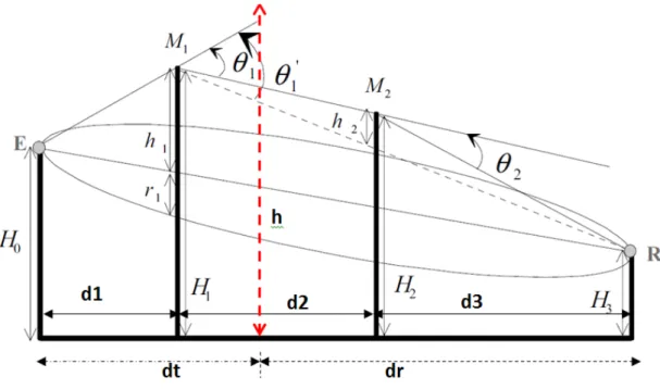
Figure 1: Geometry for the Double Knife
2.1.
Edge Diffraction Computation with Deygout method [29]
Let λ be the wavelength of the radio wave; let c be the speed of the radio wave (where c = 3x10/ and let f be the frequency of the radio wave in Hz, then, the radius of the first Fresnel zone at location x is denoted as which is at a distance of
()from the transmitter and at a distance of () from the receiver, then:
λ in metres is given as:
ʎ = "# (2) For obstruction M1,
()= d% (3)
() =d% + d'+ d( (4) Let hh% be the LOS clearance if only obstruction M1 is in the path, then:
hh% = H%− H+ − ,-.-.!-2!-0(/01 /.)3 (5)
4= ʎ(-.(-. ! -2!-0 ))(-2!-0 ) (6) For obstruction M2,
()= d%+ d' (7)
() =d( (8) Let hh' be the LOS clearance if only obstruction M2 is in the path, then;
hh' = H'− H+ − ,(-.!-2-.!-2!-0)(/01 /2)3 (9)
5 = (-ʎ(-.!-2. ! -2!-0 ))(-0) (10) In this case, obstruction M1 is considered as the dominant obstruction. Then, according to Deygout method , the LOS heights ℎ% and ℎ'are defined by the relations [28-29]:
h% = H%− H+ − ,-.(/01 /7)-.!-2!-03 (11)
h' = H'− H% − ,-2(/01 /.)-2!-0 3 (12) The knife-edge diffraction parameter v for h% is given as v% where:
v% = h%9(-.)(-2!-0)'(-.!-2!-0) (13) The knife edge diffraction loss due to v% is denoted as A%and according to ITU-RP 526-13 [31] the knife-edge diffraction loss A%is defined as:
A% = 6.9 + 20Log B,C(v%− 0.1)'+ 13 + v%− 0.1 D (14) Similarly, the knife-edge diffraction parameter v for h% is given as v% where;
v' = h''( -2!-09(-2)(-0)) (15) The knife edge diffraction loss due to v' is denoted as A'and according to ITU-RP 526-13 [30] the knife-edge diffraction loss A'is defined as:
A' = 6.9 + 20Log B,C(v'− 0.1)'+ 13 + v' − 0.1 D (16) The total diffraction loss due to the dual knife edge is A where:
A = A%+ A'
diffraction loss E defined as:
A = 6.9 + 20Log B,C(v − 0.1)'+ 13 + V − 0.1 D (17) Conversely, the diffraction parameter v can be computed from the knife-edge diffraction loss, E as follows:
Let P be defined as
10,GHI.J27 3= K (18) Also, let U be defined as
U =V -0.1 (19) Then the ITU Rec 526-13 knife-edge diffraction loss gives:
C(L'+ 1) + U = P (20) Hence,
C(L'+ 1) = P−U (21)
L'+ 1 = K'− 2(K)(L) + L' (22)
L'+ 1 = K'− 2(K)(L) + L' (23)
U =N'(N)21% (24) Then
V = OP%+
,GHI.J27 3Q21%
'P%+,GHI.J27 3Q R + 0.1
(25)
So, the single knife edge equivalent of the dual knife edge is given by equation 17. Let the single knife edge equivalent obstruction be located at a distance of ()from the transmitter and at a distance of () from the receiver, then, the diffraction parameter, V is given as:
V = h' ()! ()9() () (26) Then form
h = S
TU2, V()WV ()3 X,V()3,V ()3Y
(27)
The Percentage Clearance , Pc(%) is given as ;
Pc(%) = ,Z3 100%=(\)%++
√' (28) The excess path length (∆_`a) is the difference between the direct path and the diffracted path it is given as:
∆_`a = ,ʎb 3 c' (29) The phase difference (ϕ) between the direct path and the diffracted path is given as:
Φ = ,e' 3 c' (30) Let fg_ bethe Fresnel zone in which the tip of the obstruction lies, then:
3. Results and Discussions
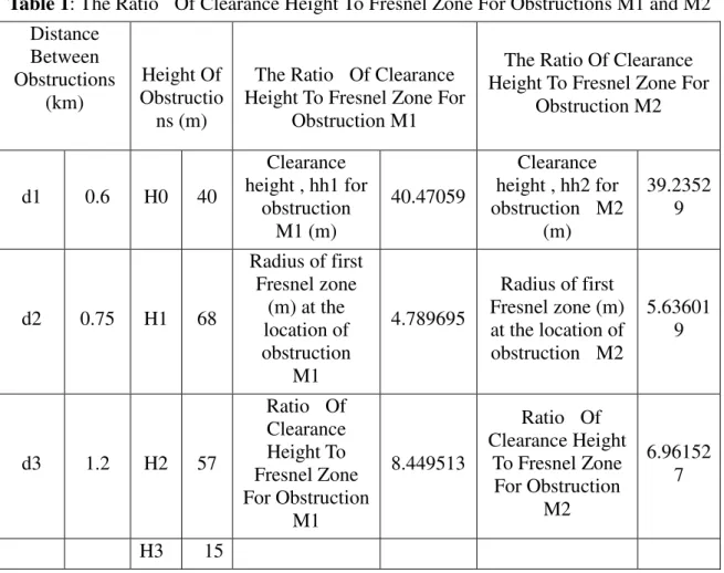
Sample dual edge obstruction is used to demonstrate the computation of single knife edge equivalent of dual knife edge obstruction based on the Deygout multiple knife edge diffraction method. Table 1 shows the height of the obstructions, the distance between the obstructions and the ratio of LOS clearance height to Fresnel zone for obstructionM1 and M2. H0 and H3 are the heights of the transmitter and the receiver respectively while H1 and H2 are the heights of the obstructions M1 and M2 respectively. From Table 1 it can be seen that the ratio of LOS clearance height to Fresnel zone for obstruction M1 is 8.449513 whereas that of M2 is 6.961527. Hence , M1 is the dominant obstruction.
Table 1: The Ratio Of Clearance Height To Fresnel Zone For Obstructions M1 and M2 Distance Between Obstructions (km) Height Of Obstructio ns (m)
The Ratio Of Clearance Height To Fresnel Zone For
Obstruction M1
The Ratio Of Clearance Height To Fresnel Zone For
Obstruction M2
d1 0.6 H0 40
Clearance height , hh1 for
obstruction M1 (m)
40.47059
Clearance height , hh2 for obstruction M2
(m)
39.2352 9
d2 0.75 H1 68
Radius of first Fresnel zone
(m) at the location of obstruction
M1
4.789695
Radius of first Fresnel zone (m) at the location of obstruction M2
5.63601 9
d3 1.2 H2 57
Ratio Of Clearance Height To Fresnel Zone For Obstruction M1 8.449513
Ratio Of Clearance Height
To Fresnel Zone For Obstruction
M2
6.96152 7
H3 15
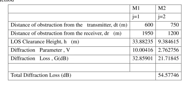
Table 2 shows the total diffraction loss of 54.57746 dB as computed by the Deygout method. The individual diffraction loss from obstructions M1 and M2 are 32.85901 dB and 21.71845 dB respectively.
Table 2: The Effective Diffraction Of The Dual Knife Edge Computed By The Deygout Method
M1 M2
j=1 j=2
Distance of obstruction from the transmitter, dt (m) 600 750 Distance of obstruction from the receiver, dr (m) 1950 1200 LOS Clearance Height, h (m) 33.88235 9.384615
Diffraction Parameter , V 10.00416 2.762756
Diffraction Loss , G(dB) 32.85901 21.71845
Total Diffraction Loss (dB) 54.57746
Table 3: The Single Knife Edge Equivalent Of The Dual Knife Edge Obstructions Single Knife
Edge Diffraction
Loss G(dB) 54.57746
Single Knife Edge Radius of First Fresnel
Zone Fr1 5.645795
Single Knife Edge
Diffraction
Parameter V 121.114
Percentage Clearance Of The Single Knife
Edge Obstruction P(%) 8564.053 Single Knife
Edge Obstruction Distance From
transmitter dt (m) 1275 Excess path length
∆_`a
(m) 183.3575 Single Knife
Edge Obstruction Distance From
transmitter dr(m) 1275 The phase difference Φ (radians) 23044.37
LOS Clearance Height of the Single Knife Edge
Obstruction h 483.5089
The Fresnel zone where the tip of the knife edge
obstruction is located ntip 7334.3
4. Conclusions
obstructions. Similar result applies to the diffraction parameter of the equivalent single knife edge obstruction in relation to the dual obstruction. Essentially, dual or multiple knife edge obstructions has more impact than a very high single knife edge obstruction.
References
[1] Corps, U. M. (1999). Antenna Handbook. Washington, DC.
[2] Bardwell, J. (2003). Math and physics for the 802.11 wireless LAN
engineer. Download from http://www. wildpackets.
com/elements/whitepapers/math_physics_jbardwell. pdf (February 5th 2009).
[3] Seybold, J. S. (2005). Introduction to RF propagation. John Wiley & Sons.
[4] Wang, F. (2006). Physics-based modeling of wave propagation for terrestrial and
space communications (Doctoral dissertation, The University of Michigan).
[5] Seun, A. T. (2007). Mobile Satellite Communications (Doctoral dissertation,
Blekinge Institute of Technology).
[6] MacCartney Jr, G. R., Deng, S., Sun, S., & Rappaport, T. S. (2016). Millimeter-Wave Human Blockage at 73 GHz with a Simple Double Knife-Edge Diffraction Model and Extension for Directional Antennas. arXiv preprint
arXiv:1607.00226.
[7] Tuset‐Peiró, P., Anglès‐Vazquez, A., López‐Vicario, J., & Vilajosana‐Guillén, X. (2014). On the suitability of the 433 MHz band for M2M low‐power wireless communications: propagation aspects. Transactions on Emerging
Telecommunications Technologies, 25(12), 1154-1168.
[8] Rao, P.S. (2013) Performance Analysis of Diffraction Gain (Gd) Due to presence of Knife-Edge as Compared to Free Space E-Field and Identifying the Position of Obstacle in a Fresnel Zone. International Journal of Scientific and Research Publications, Volume 3, Issue 1, January 2013, 1-7.
[9] Bassey, D. E., Akpan, A. O., & Udoeno, E. (2016). UHF Wave Propagation Losses Beyond 40 Percent Fresnel Zone Radius in South-South, Nigeria. International Journal of Science and Research (IJSR), 5(2), 470-475.
[10] Akkaşlı, C. (2009). Methods for Path loss Prediction. Reports from MSI, School of
Mathematics and Systems Engineering, Report, 9067.
[11] Tyson, R. K. (2014). Fresnel and Fraunhofer diffraction and wave optics.
In Principles and Applications of Fourier Optics. IOP Publishing, Bristol, UK,
3.1—3.14.
[12] Pedrotti, L. S. (2008). Basic physical optics. Fundamentals of Photonics, 1.4.,
152-154.
[13] Bock, R. D. (2016). On the Conventionality of Simultaneity and the Huygens-Fresnel-Miller Model of Wave Propagation. arXiv preprint
arXiv:1608.01544.
[14] Östlin, E. (2009). On Radio Wave Propagation Measurements and Modelling for Cellular Mobile Radio Networks, Blekinge Institute of Technology Doctoral Dissertation Series No 2009:03.
[15] Baldassaro, P. M. (2001). RF and GIS: Field Strength Prediction for Frequencies between 900 MHz and 28 GHz, Thesis, Blacksburg, Virginia.
[16] Qing, L. (2005). GIS Aided Radio Wave Propagation Modeling and Analysis
[17] Barclay, L. W. (2003). Propagation of radiowaves (Vol. 502). IET.
[18] Lazaridis, P. I., Kasampalis, S., Zaharis, Z. D., Cosmas, J. P., Paunovska, L., & Glover, I. (2015, May). Longley-Rice model precision in case of multiple diffracting obstacles. In URSI Atlantic Conference, Canary Islands.
[19] Bullington, K. (1947). Radio propagation at frequencies above 30 megacycles. Proceedings of the IRE, 35(10), 1122-1136.
[20] Vargas, T. A. A., Peña, J. E. A., Medina, J. G. B., Pulido, J. D. Z., & Peñaloza, M. L. S. (2015, October). Configuration of propagation models for computational simulation of different telecommunications services. In Engineering Applications-International Congress on Engineering (WEA), 2015 Workshop on (pp. 1-6). IEEE.
[21] Topcu, S., Goktas, P., Karasan, E., & Altintas, A. (2015, September). A new approach to diffraction modelling for line-of-sight (LOS) paths. In Antennas and Propagation in Wireless Communications (APWC), 2015 IEEE-APS Topical
Conference on (pp. 696-699). IEEE.
[22] Grecu, I. V., & Nicolaescu, M. (2016, June). Automatic propagation model tuning process in TETRA networks. In Communications (COMM), 2016 International
Conference on (pp. 229-232). IEEE.
[23] Göktas, P. (2015). Analysis and implementation of prediction models for the
design of fixed terrestrial point-to-point systems (Doctoral dissertation, Bilkent
University).
[24] Kvicera, M., Pechac, P., Grabner, M., Kvicera, V., Valtr, P., & Martellucci, A. (2015). Experimental Study on Terrestrial Links Enhancement at 11 and 38 GHz. IEEE Transactions on Antennas and Propagation, 63(7), 3179-3186.
[25] Malila, B., Falowo, O., & Ventura, N. (2015, September). Analysis of diffraction loss in NLOS small cell backhaul links deployed in urban canyons. In EUROCON
2015-International Conference on Computer as a Tool (EUROCON), 1-6.
[26] Cadavid, A. N., Rojas, R. D. F., & Bernal, M. P. (2016, October). Digital terrestrial television measurement and coverage models comparison: Evaluation of measurements and simulations on urban enviroment for DVB-T2 signals.
In Antennas and Propagation (APSURSI), 2016 IEEE International Symposium
on (pp. 1257-1258). IEEE.
[27] Deygout, J. (1961). Transmissions Multivoies par Faisceaux Hertziens. EAT
(Montargis), titre III, Fasc, 1, 139-141.
[29] Deygout J (1966) Multiple knife-edge diffraction of microwaves. IEEE Transactions on Antennas and Propagation vol AP-14, 4: 480-489
[30] Sizun, H., & de Fornel, P. (2005). Radio wave propagation for telecommunication applications. Heidelberg: Springer.
[31] ITU-R P.526-13, Propagation by diffraction, Series of ITU-R Recommendations, Nov, 2013.