Volume III, Issue XI, November- 2016
13
A STUDY OF FLOW FIELD MEASUREMENTS OF RADIAL GAB WITH
DIFFERENT RPM BY USING COMPUTATIONAL FLUID DYNAMICS
1
*S.Senthilkumar , 2Dr.Ankur Awashthi 1
* Research Scholar,Department of Mechanical Engineering, Maharishi University of Information Technology, Lucknow
2
Associate Professor, Department of Mechanical Engineering, Maharishi University of Information Technology, Lucknow
[email protected], [email protected]
Abstract
A modern trend in flow analysis in slurry impellers has long been an concentrated subject of research. The Computational Fluid Dynamics (CFD) is the present day state-of-art technique for fluid flow analysis. It was found that Un-steady as follows are created in different part with modern design conditions which result in the decreasing efficiency different radial gaps. The operating characteristic curves by the numerical simulation of velocity vectors were c o m p a r e d w i t h t h e results o f model testing and are found in good agreement. The test case consists of an enshrouded centrifugal impeller with seven blades. A large number of measurements are available in the radial gap between the impeller and the diffuse, making this case ideal for validating numerical methods with velocity vectors. Results of steady and unsteady calculations of the flow in the slurry impellers are compared with the CFD experimental ones.
Keywords: Slurry impeller model, STANDARD K-ε Model, (RNG)K- ε Model.
1. Introduction
The slurry impeller is used to transport fluid by the
conversion of the rotational kinetic energy into the
hydrodynamic energy. The pressure at outlet is a
reflection of the centripetal force that curves the
path of the water and guide to move circularly
inside the slurry impeller. This force supplied by a
pressure gradient is set up by the rotation, and the
outside pressure, at the wall of the volute, can be
considered as a reactive centrifugal force.
2. LITERATURE SURVEY
For designers, the prediction of the operating
characteristics curve is the most important. An
optimum design consideration of a mixed-flow
impeller blade was the main focus of the research
by (Li et al 2012) and the analysis was carried out
using CFD improvement of the performance of the
designed impeller achieved by under-filing the
impeller blades at the trailing edge. The
investigators emphasized the need to integrate CFD
software to the design process on a continuous
basis. Further, some important considerations from
the manufacturing viewpoint were enumerated.
These include selecting the suitable blade and vane
thicknesses, blade swirl and vane angles.
3. RESEARCH OBJECTIVE
i. Achieving the very best practice of CFD to
International Journal On Engineering Technology and Sciences – IJETS™
ISSN(P): 2349-3968, ISSN (O): 2349-3976 Volume III, Issue XI, November- 2016
14 ii. To compare various turbulence models such
as K Epsilon RNG Model and K Epsilon
STD Model
4. DESIGN AND SPECIFICATION OF
THE SLURRY IMPELLER
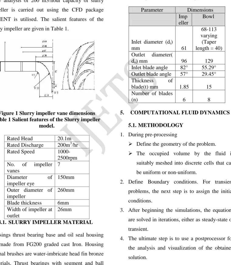
Flow analysis of 200 m3/hour capacity of slurry
impeller is carried out using the CFD package
FLUENT is utilised. The salient features of the
slurry impeller are given in Table 1.
Figure 1 Slurry impeller vane dimensions Table 1 Salient features of the Slurry impeller
model.
Rated Head 20.1m
Rated Discharge 200m3/hr
Rated Speed
1000-2500rpm No. of impeller
vanes
7
Diameter of
impeller eye
150mm
Outer diameter of impeller
260mm
Blade thickness 6mm
Width of impeller at outlet
26mm
4.1. SLURRY IMPELLER MATERIAL
Housings thrust bearing base and oil seal housing
are made from FG200 graded cast Iron. Housing
journal brushes are water-imbricate head fin bronze
materials. Thrust bearings with segment and ball
type are used to ensure wide thrust heads. Winding
is made by poly wrap wires, which are cooled by
water. The parameters identified for this existing
impeller model is listed below in Table 2
Table 2 Specification of the impeller and bowl
Parameter Dimensions
Imp eller
Bowl
Inlet diameter (di)
mm 61
68-113 varying
(Taper length = 40) Outlet diameter(
do) mm 96 129
Inlet blade angle 82° 55.29° Outlet blade angle 57° 29.45°
Thickness of
blade(t) mm 1.85 15
Number of blades
(n) 6 8
5. COMPUTATIONAL FLUID DYNAMICS
5.1. METHODOLOGY
1. During pre-processing
Define the geometry of the problem.
The occupied volume by the fluid is
suitably meshed into discrete cells that can
be uniform or non-uniform.
2. Define Boundary conditions. For transient
problems, the next step is to assign the initial
conditions.
3. After beginning the simulations, the equations
are solved in iterations, either as steady-state or
transient.
4. The ultimate step is to use a postprocessor for
the analysis and visualization of the obtained
ISSN(P): 2349-3968, ISSN (O): 2349-3976 Volume III, Issue XI, November- 2016
15
5.2.MESHING OF SLURRY IMPELLER
ASSEMBLY:
In Computational Fluid Dynamics, meshing is a
discrete representation of the geometry involved in
the case. Essentially, it assigns cells or smaller
regions over which the solution is obtained. Several
parts of the mesh are grouped into regions where
boundary conditions may be applied to solve the
problem. Moreover, the uses of meshing are not
limited to computational fluid dynamics. Also,
meshing can be used to solve partial differential
equations using Numerical Techniques.
5.3. GRID GENERATION
Using ICEM CFD, the grid for the 3-D model was
created. Care was taken in distribution of grid
elements in the model, because of the size and
complexity of the impeller. Considering the
geometric complexity, unstructured grid which
consists of tetrahedral and triangular element with
ICEM CFD scheme was used.
5.4. BOUNDARY CONDITIONS AND
TURBULENCE MODELS
The simulations were carried out over a six
different operating points with two different
turbulence models namely renormalization group
(RNG) k-ε model and shear stress transport (SST)
k- ε model. Mass flow rate corresponding to
different operating points were specified at the
suction of impeller while total pressure was defined
at the casing outlet
Table 3 Boundary condition
Parameters CFD
Fluid used for simulation Water at 25°C
Pressure at Inlet Pressure = 0 Pa
Total Pressure at Outlet 328438.85 Pa
Density of Fluid 1000 Kg/m3
Viscosity 1.0031e-3 kg/m-s
Turbulence Model K-ε , RNG Model
RPM range 1000 to 1500
5.5. CONVERGENCE CRITERIA
The residual of mass flow rate between inlet and
outlet should be kept at e-5 (5th decimal accuracy)
as shown in Figure 2.
Figure 2 Convergence monitoring
Table 4: Mesh count
Case Study
Surface Mesh Count
Volume Mesh count
Q - CFD at BEP Lps
Case 1 1,15,624 8,23,175 9.77
Case 2 1,91,645 14,64,522 9.32 Case 3 3,32,579 16,00,292 9.25 Case 4 4,31,462 20,22,124 9.19 Case 5 4,89,513 26,23,489 9.20 Case 6 5,11,336 29,46,178 9.20
Mesh count is a significant variable which the CFD
results rely on. Mesh count ranges from 8 lakh
tetrahedrons to around 29 lakh tetrahedrons
International Journal On Engineering Technology and Sciences – IJETS™
ISSN(P): 2349-3968, ISSN (O): 2349-3976 Volume III, Issue XI, November- 2016
16
6. RESULTS AND CONCLUSIONS
6.1.VELOCITY MAGNITUTE VALUES
6.1.1. K-Epsilon RNG model results
In this functions of the velocity magnitude values
variation is uniform at rated discharge 1035rpm and
1150rpm ,1265 rpm are compared in Kepsilon
-realizable functional equation to apply equation
form analysis based analyzed model but
comparatively non-uniform at other operating
conditions. single Plane and single radial gap are
attached of casing for different operating
conditions. Shows the velocity variation in the
central pressure acting in the different parts.
Fig 3 contour plot Velocity contour 1035 RPM
Above figure 3 this functionally flow equation in
K-Epsilon turbulence model analyzed in rotational
wall functions based to take a result to be done in
static pressure - initialization operating conditions
are 1035 rpm. Results achieved in maximum values
accrue velocity 1.80e+01 m/s
Fig 4 contour plot Velocity contour 1150 RPM
Above figure 4 this functionally flow equation in
K-Epsilon turbulence model analyzed in rotational
wall functions based to take a result to be done in
static pressure - initialization operating conditions
are 1150 rpm. Results achieved in maximum values
accrue velocity 3.0e+07 m/s
Fig 5 Contour plot Velocity contour 1265 RPM
Above figure 5 this functionally flow equation in
K-Epsilon turbulence model analyzed in rotational
wall functions based to take a result to be done in
static pressure - initialization operating conditions
are 1265 rpm. Results achieved in maximum values
accrue velocity 2.31e+05 m/s.
6.1.2. K-EPSILON STANDARD
MODEL RESULTS
In this functions of the velocity magnitude values
variation is uniform at rated discharge 1035rpm and
1150rpm ,1265 rpm are compared in Kepsilon
-realizable functional equation to apply equation
form analysis based analyzed model but
comparatively non-uniform at other operating
conditions. Single Plane and single radial gap are
ISSN(P): 2349-3968, ISSN (O): 2349-3976 Volume III, Issue XI, November- 2016
17 conditions. Shows the velocity variation in the
central pressure acting in the different parts.
Fig 6 contour plot Velocity contour 1035 RPM
Above figure 6 this functionally flow equation in
K-Epsilon turbulence model analyzed in rotational
wall functions based to take a result to be done in
static pressure - initialization operating conditions
are 1035 rpm. Results achieved in maximum values
accrue velocity 1.80e+07 m/s
Fig 7 contour plot Velocity contour 1150 RPM
Above figure 7 this functionally flow equation in
K-Epsilon turbulence model analyzed in rotational
wall functions based to take a result to be done in
static pressure - initialization operating conditions
are 1265 rpm. Results achieved in maximum values
accrue velocity 2.10e+02 m/s
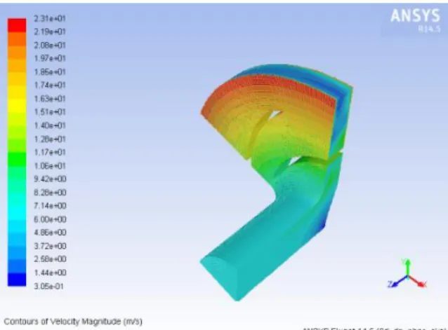
Fig 8 contour plot Velocity contour 1265 RPM
Above figure 8 this functionally flow equation in
K-Epsilon turbulence model analyzed in rotational
wall functions based to take a result to be done in
static pressure - initialization operating conditions
are 1265 rpm. Results achieved in maximum values
accrue velocity 2.31e+01 m/s
Table 5 Velocity Magnitude Comparison
Sl.
No. RPM
K-EPSILON
RNG MODEL
K-EPSILON STANDARD
MODEL
1 1035 1.8e+01 1.8e+07
2 1150 3.0e+07 2.10e+02
3 1265 2.31e+05 2.31e+01
7. CONCLUSION
Based on the numerical analysis of CFD for slurry
impeller the following results are achieved they are
1. Out of various mesh counts 20, 22, 124
elements was found to be optimum.
2. K- ε minimum deviation from the
International Journal On Engineering Technology and Sciences – IJETS™
ISSN(P): 2349-3968, ISSN (O): 2349-3976 Volume III, Issue XI, November- 2016
18 3. Second order discretization scheme with
simple algorithm for velocity contours hold
good for this analysis.
The flow through a slurry impeller was analyzed
using commercial CFD package FLUENT for
which model test results were available. The
simulations were carried out at six different
operating points between 10% to 20% radial gab
different discharge, to cover the wide range of
operation, with two different turbulence models.
The following conclusions were drawn from the
analysis:
A Reynolds-averaged Navier- Stokes code with a
two equation turbulence model is able to predict the
important flow physics in a slurry impeller.
It was found that k-ε SST turbulence model
provides better results compared to RNG k- £
The selection of speed ranges to simulate in
different flow study equations basis to following this
method.
It was found that speed range 1035 rpm k- ε SST
turbulence model provides better results compared to
k- ε RNG model. Dynamically apply the overhead
pressure are flowed.
It was found that speed range 1265 rpm K- ε
RNG turbulence model provides better results
compared to k- ε SST model. Dynamically apply the
overhead pressure are flowed in higher velocity.
It was found that speed range 1150 rpm K- ε
RNG turbulence model provides better results
compared to k- ε SST model. Dynamically apply the
overhead pressure are flowed in higher velocity.
The given operating condition slurry impeller
which executes maximum velocity value at 1150 rpm.
REFERENCES
1. Muggli F.A., Eisele K., Casey M.V., Gulich J., Schachenmann A., 1997. Flow analysis in a pump diffuser-part2: validation and limitations of cfd for diffuser flows, Journal of Fluids Engineering, 119, 978-984.
2. Patel K. and Ramakrishnan N., CFD analysis of mixed flow pump. Spence R., Teixeira J.A., 2009. A CFD parametric study of geometrical variations on the pressure pulsations and performance characteristics of a centrifugal pump. Computers & Fluids, 38, 1243–1257. 3. Combès, J.F., "Test Case U3: Centrifugal Pump
with a Vaned Diffuser", ERCOFTAC Seminar and Workshop on Turbo machinery Flow PredictionVII, Aussois, Jan 4-7 , 1999.
4. Ubaldi, M., Zunino, P., Barigozzi, G. and Cattanei, A., "LDV Investigation of the Rotor-Stator Aerodynamic Interaction in a Centrifugal Turbomachine", 8th International Symposium on Applications of Laser Techniques to Fluid Mechanics, Lisbon, 1996.
5. Canepa, E., Cattenei, A., Ubaldi, M. and Zunino, P., "Wake-boundary layer interaction on the vaned diffuser of a centrifugal state", Proc. IMechE, vol. 219, Part A: J. Power and Energy, 401-411, 2005.
6. Bert, P.F., "Modélisation des écoulements instationnaires dans les turbomachines par une méthode éléments finis", Doctoral Thesis, Institut National Polytechnique de Grenoble, 1996.
7. Bert, P.F., Combès, J.F. and Kueny, J.L., "Unsteady Flow Calculation in a Centrifugal Pump Using a Finite Element Method", Proceedings of the XVIII IAHR Symposium on Hydraulic Machinery and Cavitation, 371-380, 1996.
8. Torbergsen, E. and White, M.F., "Transient Simulation of Impeller/Diffuser Interactions", Proceedings of the 1997 ASME Fluids Eng Division Summer Meeting, FEDSM97-3453, 1997.
9. He, L. and Sato, K., "Numerical Solution of
Incompressible Unsteady Flows in
Turbomachinery", Proceedings of the 3rd
ASME/JSME Joint Fluids Eng Conf,
ISSN(P): 2349-3968, ISSN (O): 2349-3976 Volume III, Issue XI, November- 2016
19 10.Prashant Bhatt, Rajesh Satankar, '
Computational Fluid Dynamics analysis of wind turbine rotor blades- A review', IJCRR, 4(21).
11.Ban,J.O, Lee,U.S, Ahn, B.H, Kin,Y.S, 'Application of Computational Fluid Dynamics to Rotary Compressor Efficiency and Noise', International Compressor Engineering Conference.