Modeling and Analysis (Gravity & Seismic) of Two Different Buildings
with and Without Infill Walls Using Software Sap2000
1P.Kumar,2S.Sivacharan,3C.Rajesh,4Ch.Bhaskara Rao
1M.Tech (Student) Structural Engineering,2Associate Prof.,3Bridge Design Engineer,4Asst.Prof.
1,2,4Aditya college of engineering & technology, Surampalam
3
feedback infra private limited, Bangalore.
Abstract
Reinforced Concrete framed structures are consistentlyincluded in the building developments which are framed as exposed edge structures and for the most part the casings in the uncovered edge structures are filled by workmanship infill or concrete pieces in numerous nations arranged in seismic districts. The nearness of infill divider in RC Frames offers a monetary and tough arrangement as well as improving the quality and solidness of edge by acting like pressure strut in the middle of the void space of segment and shaft in RC Framed structures and exchange the compressive powers starting with one hub then onto the next. It is plainly frames that the nearness of infill divider has noteworthy basic ramifications within the sight of buildings in earthquakes (like Bhuj quake). The execution of RC Framed buildings with and without infill walls is seen by this investigation. Here investigated and frame the workmanship infill walls as pressure struts by receiving identical corner to corner strut idea, to evaluate the contribution of infill divider in seismic resistance of customary RC Buildings. Modeling the two diverse multi storied buildings (G+5, G+9) with and without infill walls and planned it and investigated for horizontal burdens utilizing programming (SAP 2000). Modeled the strut buildings as double strut model, triple strut models for both the structures and looking at the got comes about because of the modernized model investigation for with and without infill divider structures. At long last, we check the outcomes for add up to weight of building, Base shear, time period, and zone of steel required by building and model interest mass proportion for the looking at of results
Keywords: Seismic Analysis of Multi-Story Building,Bare-frame, Infill Walls, Equivalent Diagonal Strut.
I. Introduction
these lines the commitment of infill stone work widy affects multi story stuctures, despite the fact that emphatically relying upon the attributes of the ground movement, particularly for frames which has been planned without considering the seismic powers. At the point when sudden change in solidness happens along the building tallness, because of its stature varieties, the story at which this exceptional difference in firmness happens is known as a delicate story. As per IS 1893(Part-I): 2000, a delicate story is the one in which the sidelong firmness is under half of the story above or beneath. Another essential issue is identified with the numerical reenactment of infilled frames. The diverse systems for glorifying this basic model can be isolated into two nearby or small scale models and streamlined full scale models. The primary gathering includes the models, in which the structure is isolated into various components to assess the nearby impact in detail, though the second gathering incorporates disentangled models in light of a physical comprehension of the conduct of the infill board. In this examination the quality and solidness of the block stone work infill is considered and the block brick work infill is modeled utilizing slanting strut, as two askew parallel strut and three corner to corner parallel strut, has been model under programming bundle SAP 2000.The investigation is performed utilizing "Straight static investigation" for understanding the change in firmness parameters of the structure.
II. Related Work
Stafford-Smith B [1] To propose the viable width of the equal strut and presumed that this width ought to be an element of the solidness of the in-load as for that of jumping frame, by considering versatile hypothesis. He characterized the dimensionless relative parameters to decide the level of edge in-fill association and in this way, the powerful width of the strut by investigating a shaft on versatile establishments. And furthermore characterized the detailing of exact conditions to the ascertain the infill divider parameter as strut model, for example, contact length of strut, powerful width of the strut.
Holmes [2] was the first in supplanting the infill by a proportionate stick jointed inclining strut. He influenced a proposition on the modeling of infill to divider as the slanting strut of the investigation and plan of the single story single-cove structure of know the better exhibitions of the structure with its parallel
solidness and the time period of the building. He presented the hypothesis of finding the successful width and contact length of the inclining strut.
Das and C.V.R. Murty [3] together did a non-straight weakling investigation on five RC frame buildings with block stone work in-fill walls, and he intended for the same seismic peril as per the Euro-code, Nepal Building Code and Indian code and the comparable propped frame strategy given in writing. He expressed that the In-fill walls of structure are found to build the quality and firmness of the structure, and decrease the float limit alongside basic harm. Toward the end saw that, in-fills decrease the general structure pliability, yet increment the general quality. Building composed by the proportional supported edge strategy demonstrated better general execution.
Amato et al. [4] talked about the mechanical conduct of single story-single cove in-filled casings and disentangled logical techniques accessible in the writing for the separation of a stick jointed strut comparable to the in-fill to consider the impact of vertical burdens. Point by point numerical examination on in-filled cross sections has demonstrated that within the sight of vertical burdens it is conceivable that a solid connection between's the measurement of the comparable corner to corner strut model and a solitary parameter, which relies upon the qualities of the framework. A group of bends has acquired for various estimations of vertical load.
V.K.R.Kodur et al. [5] considered a three story RC frame building models for the investigation by thought of examination of three cases in RC frames like I) Bare edge ii) Infilled frame iii) Infilled frame with openings. In view of the examination comes about they found that Base shear of infilled frame is more than infilled frame with openings and exposed casing. Time period of infilled frame is less as contrast with infilled frame with openings and uncovered casing. The characteristic recurrence of infilled frame is more as contrast with infilled frame with openings and uncovered edge.
nonlinear static weakling examination is completed to decide the limit bends. It is watched that the quality of the edge with infill is 10 times more than the conventional exposed edge. The infill divider viably takes an interest in opposing the parallel powers alongside the RC frame, and furthermore there is a gigantic variety of float limits between a similar size of an uncovered casing and an edge with infill. Consequently the pliability of the edge increments with the inclusion of the infill walls. While expanding in number of stories, the quality of the uncovered edge increments, clearly, though the quality of the edge with infill diminishes one might say that the distinction in conduct of exposed casing ought be confirmed on a solitary story as well as to be checked with various number of stories.
Haroon Rasheed Tamboli [6] considered the uncovered casing and infill model structures and plays out the seismic investigation to watch the variety in both the structures. In this infill frame, structures acts stiffer when contrasted with exposed edge structure and furthermore open ground story impact the structure amid the tremor which cause sudden crumple amid the solid ground shaking. His paper says that the infill will expand the quality and firmness of structure and in nearness of infill divider it influences the seismic conduct of RC framed structure to huge degree.
III. Modeling & analysis of bare-frame buildings
Considered two buildings of G+5 & G+9 storeys having same floor height and similar properties of the structures. Both the buildings are modeled as bare-frame i.e., buildings without considering infill walls between the vertical and horizontal elements of the building. These are analyzed for gravity loads and seismic loads in the software as per IS 1893(Part-1):2002 condition of analysis.
Preliminary Data
Considered two different building of different heights like G+5 and G+9 storeys RC framed buildings of same storey levels to analyse the seismic performance of those buildings. The general parameters required for the modelling of the two buildings, G+5 and G+9 and has the same parameter are taken as follows:
Type of frame :Special RC moment resisting frame fixed at the base
Seismic zone V
Number of storeys :G+5 & G+9
Floor height :3.5 m
Plinth height :1.5 m
Depth of Slab :150 mm
Spacing between frames :5m along both directions
Live load on floor level :4 kN/m2
Live load on roof level :1.5 kN/m2
Floor finish :1.0 kN/m2
Terrace water proofing :1.5 kN/m2
Materials :M 20 concrete, Fe 415 steel and Brick infill
Thickness of infill wall :250mm (Exterior walls)
Thickness of infill wall :150 mm (Interior walls)
Density of concrete :25 kN/m3
Density of infill :20 kN/m3
Type of soil:Medium
Response spectra :As per IS 1893(Part-1):2002
Damping of structure :5 %
**Live load on floor level and roof level are taken from IS-875 (Part-) considered RC framed buildings as commercial usage.
Member Properties
Dimensions of the beams and columns are determined on the basis of trial and error process in analysis of SAP2000 by considering nominal sizes for beams and columns and safe sizes are as show in the table below.
Type of Anal
Gravity Building
ysis building
Member s
BE AM
COUL UMN
BE AM
COUL UMN
G+5 store y
Buil ding
INITIA L
PROPE RTIES
0.30 x 0.30 m
0.40 x 0.40 m
0.30 x 0.30 m
0.40 x 0.40 m
Final propertie s
0.40 x 0.40 m
0.50 x 0.50 m
0.50 x 0.50 m
0.60 x 0.60 m
G+9 store y
Buil ding
INITIA L
PROPE RTIES
0.45 x 0.45 m
0.50 x 0.50 m
0.50 x 0.50 m
0.60 x 0.60 m
Final propertie s
0.50 x 0.50 m
0.60 x 0.60 m
0.55 x 0.55 m
0.70
0.70 m
Load Calculations
In among the models,like bare frame model, two diagno-parellel strut model and three diagno-parellel strut models of both the G+5 and G+9 buildings have the same load pattern in which loads of slab is transferred on to beams using yield line theory. As per Yield line theory, the load distributes on slab into triangle and trapezoidal form of distribution as shown in the figure.
Figure: Load Carried By Supported Beams
As per IS CODE: SP-24-(1983) bending moments generated by the beams may be determined with sufficient accuracy by assuming that the loading is
equivalent to a uniform load per unit length of the beam is as follows:
On the short span UDL
On the long span UDL
Where, lx= Shorter span, ly= Longer span W =
Load per unit length The slab panel of considered structure length is equal in both the span directions as lx = ly, so we have the used the formula for
calculating uniform load per unit length is ).
Also wall load is induced on the beam as uniform load only which is calculated as: Uniform wall load in beam(w) = Thickness of wall x Height of wall x Unit Weight of brick masonry.
Design Imposed Loads for Earthquakes Force
As per IS 1893-2002 (Part-1), Clause 7.3.1, for various loading classes as specified in IS 875-1987 (Part 2), the earthquake force shall be calculated for the summation of full dead load and the percentage of imposed load as given in table 3.3. The percentage of imposed load is also known as mass source of the building.
Table: Percentage of Imposed Load
Imposed Uniformity Distributed Floor
loads
(kN/m2)
Percentage of Imposed Loads
(%)
Up to and including 3.0 25%
Above 3.0 50%
** Here,in the calculation of seismic weight manually and analysis in SAP2000 considered percentage of imposed load of 50% as if we have live load 4 kN/m2.
IV. Modelling & Analysis of R.C. Framed building Without Infill Walls (Bare Frame Model)
Considered G+5 and G+9 R.C framed buildings were modelled in SAP2000 software package based on the preliminary data mentioned in earlier sections. The building is modelled as 3D-framed building with member and material properties as bare frame model without infills walls but considered the load and strength of the brick masonry on the beams. Modelled two buildings which are G+5 and G+9 storey buildings with same floor height of 3.5m and plinth height of 1.5m and lengths in both x, y-direction is 5m and with similar properties of the building without infill walls. The model of the buildings, shown in the figures.
Figure: Plan of G+5 & G+9 storey building of all models
Figure: 3D-view of G+5 storey Bare-frame model
Figure: 3D-view of G+9 storey Bare-frame model
Figure: Dead load on G+5 storey Bare-frame model on Interior frame
V.Analysis of RC Frame Buildings with Infill Walls (As Two Diagonally Parallel Strut Model)
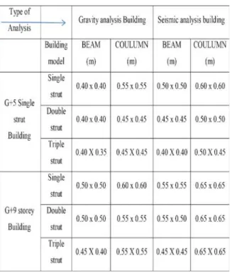
Member properties
and its properties of members are noted in the table as shown.
Table: Member Properties of G+5 & G+9 Storey Strut Model Buildings
Material Properties
M-20 grade of concrete and Fe-415 grade of reinforcing steel are used for all the frame models used in this study. Elastic material properties of these materials are taken as per Indian Standard IS 456: 2000. The short-term modulus of elasticity (Ec) of
concrete is taken as:
fckis the characteristic compressive strength of
concrete cube in MPa at 28-day (20 MPa in this case). For the steel rebar, yield stress (fy) and
modulus of elasticity (Es) is taken as per
IS 456:2000. The material chosen for the infill walls was masonry whose compressive strength (fm’) from
the literature was found out to be 20 MPa and the modulus of elasticity
of masonry is considered as 13800MPa. Considered Poisson’sratio of concrete, rebar steel and masonry is 0.3, 0.3 and 0.2 respectively.
Case study of R.C Framed Buildings With Infill Walls–Diagonal Strut Models(Single strut)
In the previous chapters, bare frame buildings are analyzed for both gravity and seismic loads separately and have seen the results of it. Now, by considering the wall as an element in the structure and the building is analyzed here for both gravity and seismic loads. These masonry infill walls are modelled as the equivalent diagonal strut. The material properties of the strut are similar to that of masonry infill wall. The model of equivalent diagonal strut is shown in the fig.
Figure 4.1: Equivalent Diagonal Strut model
In modelling the equivalent diagonal strut major part is to find the effective width of the strut in which it depend on length of contact between wall and column and between wall and beam. Stafford smith estimated the formulations for αhand αLon the basis
of beam on an elastic foundation. Hendry introduced the equation to find the equivalent diagonal strut width. The following equations are proposed to determine αh and αL, which depend on the relative
stiffness of the frame and infill walls, and on the geometry of panel.
Where,
Emand Ef= Elastic modulus of the masonry wall and
L, h, t = Length, height and thickness of the infill wall, respectively
Ic, Ib = Moment of inertial of column and
the beam of structure, respectively
= angle of inclination of diagonal strut
The equation is used to determine the equivalent or effective strut width (wd), length (Ld) and area of strut
( Ad), where the strut is assumed to be subjected to
uniform compressive stress.
By using these formulas the effective width, length and area of the diagonal strut is calculated.
Modelling & Analysis of Double–Strut Buildings
It must be noted that the stiffness depends on the contact length of beam and column to the strut. Double strut will act mores stiffer than the single strut comparatively based on the base shear and the time period of the structure. The difference in the number of bays and number of storey will show the changes in the increase of stiffness and shear but not decreases the displacement of the structure.
Figure: Diagonal Double-Strut Model
Here the double strut model is done for G+5 and G+9 storey building using the properties defined in Sec.4.1.1. Chap-4, and the properties of struts like height and area of section are calculated as formulas
defined in previous section and the width of the strut in double strut model is half the single strut model.
i.e., W 1= Wd2= Wd= Width of the double strut
Vertical distance between the struts
Figure: Elevation of G+5 storeys Double-Strut Model Building
Figure: Extrude View of G+5 storeys Double-Strut Model Building
VI. Comparison of Analysis Results
Comparison of Gravity Load analysis & Earthquake analysis of Bare-Frame Buildings
Table: Comparison of Manual & SAP 2000 Results of Bare–frame Buildings
Comparison of Manual & SAP 2000 Results of Bare–frame Buildings
Type of struct ure Anal ysis Total weight (kN) Time period (Sec.) Base shear (kN) Man ual SA P 200 0 Man ual SA P 200 0 Man ual SA P 20 00 G+5 Gravi ty 4211 4 511 95 - 1.7 5 - -Seis mic 4623 5 558 92 0.77 4 1.1 85 3935 47 59 G+9 Gravi ty 7630 9 921 23 - 2.0 03 - -Seis mic 8168 8 979 76 1.11 3 1.6 7 4868 58 02
Comparison of results of Bare-frame & Strut Model Buildings
In this report completed the analysis of bare-frame and strut models on both G+5 & G+9 storey buildings in which strut model includes the three different model of strut. For the modelled structures performed gravity and seismic load analysis using the software SAP 2000 and drawn-out the results and compared as show in the table.
Table: Comparison of Gravity Load Analysis Results of all Struts
Type of structure
Model Analysis Total Weight (kN) Time period (Sec.) G+5 Bare frame
Gravity 51195 1.705
Double strut
Gravity 50527 0.282
Triple strut
Gravity 49827 0.253
G+9
Bare frame
Gravity 92123 2.003
Double strut
Gravity 90811 0.499
Triple strut
Gravity 86961 0.452
Table: Comparison of Modal Participation of Mass ratio for
Seismic Analysis of all Model Buildings
Comparison of Modal Participation Mass Ratio for Seismic Analysis
Type of struct ure Mod el Mode 1 (Unit-less) Mode 2 (Unit-less) Mode 3 (Unit-less)
Ux Uy Ux Uy Ux Uy
Dou ble Stru t
0.3 36
0.3 40
0.3 21
0.3 17
0.1 16
0.1 19
Trip le Stru t
0.3 18
0.3 43
0.3 15
0.2 90
0.1 18
0.1 26
Seismic Analysis of G+5 storey Models in X-direction
Seismic Analysis of G+5 storey Models in Y-direction
Seismic Analysis of G+9 storey Models in X-direction
Seismic Analysis of G+9 storey Models in Y-direction
In the above charts drawn for both the buildings for comparison of modal mass participation ratio of both the structures models and considered only first three mode shape values only. In this observed that modal ratio varies from model to model and also depend on stiffness of the structure and also the time period of the structure. From the charts it shows that stiffer the structure then the lesser the time period, and lesser the modal mass ratio of the structure. Also the triple strut shows the better performance of the buildings because the struts are connected between column-beam and distribution of mass is also good comparing to other strut models.
VII. Conclusion
the during the earthquakes in the high seismic prone regions which can with stand for high seismic intensity also.
This concludes that while doing the analysis and design of the buildings it is better to analysis by considering the stiffness of infill walls(triple strut model) which helps in knowing the actual performance of the building and is safe to design building with stiffness of infill consideration. As if we have seen the collapse of buildings during the Bhuj earthquake which are analyzed and designed without considering the stiffness walls which causes sudden failure of the structure. So, better to analyses the structures by considering stiffness of infill walls.
Future Scope
i. Perform non-linear pushover analysis for both bare-frame and strut models to know the failures in the structures.
ii. Analysis the buildings by modelling wall as an area element and can compare the performance with the strut models and bare-frame model.
References
1. a. Stafford Smith B, Lateral stiffness of infilled frames, Journal of Structural division, ASCE, 88 (ST6), 1962, pp. 183-199.
b. Stafford Smith B. Behaviour of Square Infilled Frames. Proceedings of the American Society of Civil Engineers, Journal of Structural Division, 92, no STI, 381-403, 1966.
c. Stafford Smith B, Carter C. A method of analysis for infill frames. Proc. Inst. Civil Engineering, 1969.
2. Holmes M. Steel frames with brickwork and concrete infilling. Proceedings of the Institution of Civil Engineers 19, 1961.
3. A. DAS D AND MURTY C V R, Brick Masonry Infills in Seismic Design of RC Frame Buildings: Part 2- Behaviour, TheIndian Concrete Journal, 2004.
4. A. AMATO G, CAVALERI L, FOSSETTI M, AND PAPIA M, Infilled Frames: Influence of Vertical Load on The Equivalent Diagonal Strut Model, The 14th World Conference on Earthquake Engineering, Beijing, China, 2008.
5. V.K.R.Kodur, M.A.Erki and J.H.P.Quenneville “Seismic analysis of infilled frames” Journal of Structural Engineering Vol.25, No.2, July 1998 PP 95 -102.
6. HaroonRaheedTamboli and UmeshN.Karadi, Seismic Analysis of RC Frame Structures With and Without Masonary Walls, Indian Journal of Natural Sciences, Vol.3/Issue14, Oct.2012.
7. Patnala V S Neelima, Ramancharla Pradeep Kumar, Seismic Behaviour of RC Frame with URM Infill: A Case Study, International Journal of Education and Applied Research (IJEAR), Vol.4, Issue Spl-2, Jan-June 2014..
8. A.Mohebkhah, A.A.Tanimi, and H.A.Moghadam, A Modified Three-Strut (MTS) Model for Masonry-InfilledSteel Frames with Openings, Journal of Seismology and Earthquake Engineering, Vol.9, No.1,2 , Spring and Summer 2007.
9. Robin Davis, Praseetha Krishnan, DevdasMenon, A. Meher Prasad, Effect of Infill Stiffness on Seismic Performance of Multi-Storey RC Framed Buildings in India, 13th World Conference on Earthquake Engineering, Vancouver, B.C., Canada, Paper No. 1198, August 1-6, 2004