An Introduction to SCADA-ICS
System Security
Document Number
IG-101
Document Issue
0.1
Overview
Supervisory Control And Data Acquisition (SCADA) for Industrial Control Systems has become a topic of concern from a security perspective since these technologies control much of the infrastructure that we rely on in our everyday life: from lifts in buildings, to air-conditioning, to power generation, to aircraft management. They all rely on networked, interconnected control systems.
Historically, the threat was minimal because the protocols used by SCADA/ICS systems were bespoke, and local. However, as standardisation has created interoperable equipments and networking technology has migrated towards IP connectivity, SCADA/ICS systems are now accessible, and increasingly, attackable from the Internet.
This short whitepaper is intended to introduce the reader to SCADA/ICS systems, the standards and documents involved, and an understanding of the basis of the potential threats and risks.
Supervisory Control
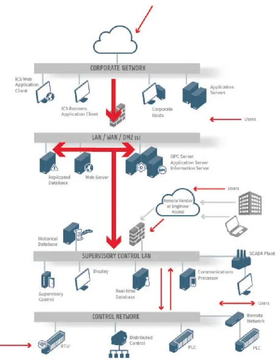
The following diagrams (Figures 1-3) illustrate a typical SCADA/ICS system1. It is drawn as an interconnected set of networks, each providing a different operational function. This concept of ‘zoning’ the network into multiple security levels or ‘zones’, interlinked with
‘conduits’ is good practice as described in ANSI/ISA-992.
The Business System
The Corporate (or Enterprise) Network hosts the business services (sometimes termed Business Support Systems – BSS, Business Information Systems – BIS or Management Information Systems - MIS) of the company. These services typically ‘reach down’ into the SCADA system to extract business information such as uptime, failures, and other metrics that affect performance and costs. In some cases the Operations
and Maintenance (O&M) functions (sometimes termed Operational Support Systems – OSS) may also be at this level, though typically they exist in the supervisory SCADA layer of the framework. In larger organisations a Network Operations Centre (NOC) approach is taken for O&M/OSS operations with multiple centres implemented in some cases in order to meet recovery point and recovery time objectives. The terms of reference for the O&M/OSS include managing the system, coordinating outages for repairs and maintenance, and interfacing with third party service providers, e.g. network connectivity, Machine-to-Machine (M2M) radio connection services, and so on.
1 CPNI document “Cyber Security Assessments of Industrial Control Systems – A Good Practice Guide”
2 ANSI/ISA-99 describes a suite of standards many of which have not yet been completed. They are listed under ISA-62443 and include a
number of releases of subsets of the suite under the ANSI-99 standard name. A description of the standard can be found here: http://isa99.isa.org/ISA99%20Wiki/WP_Overview.aspx, and a summary of the standard in the ICS context here:
http://www.tofinosecurity.com/sites/default/files/ANSI_ISA-99%20and%20Intrinsically%20Secure%20Systems%20%28May%202009%29.pdf
Figure 2 – Illustrative SCADA/ICS system with typical attack vectors between the security zones marked in red
Large organisations typically have Wide Area Network (WAN) connectivity to support multiple site locations and business offices. These may be connected using the Inter-Control Centre Communications Protocol (ICCP). Across this WAN (or local network LAN in some smaller business cases) data is captured from the SCADA (Supervisor control and data acquisition) network.
The Corporate network is typically protected with a dual or triple firewall DMZ (from the term de-militarised zone – a segregated area of the network that usually hosts services that need to be accessed by both trusted/secure internal LAN and un-trusted/insecure public internet e.g. Web & proxy servers, Historian Database, e-mail, DNS, FTP, VoIP etc).
Supervisory Control Connectivity
A number of SCADA/ICS servers are typically connected using the WAN, using the OPC protocol3. OPC-HDA is typically used to ‘reach down’ into the SCADA/ICS Data Historians (marked ‘Historical Database’ in Figures 1, 2) to offer the data ‘upwards’ to the BSS on the corporate/enterprise network. This data includes trend information, anomalies or events in the plant process being monitored, and so on. In small, and some legacy installations, OPC (specifically OPC-DA1, 2 or 3) may also be used for direct control of, and connection between, equipments and Human Machine Interfaces (HMI) on the control network.
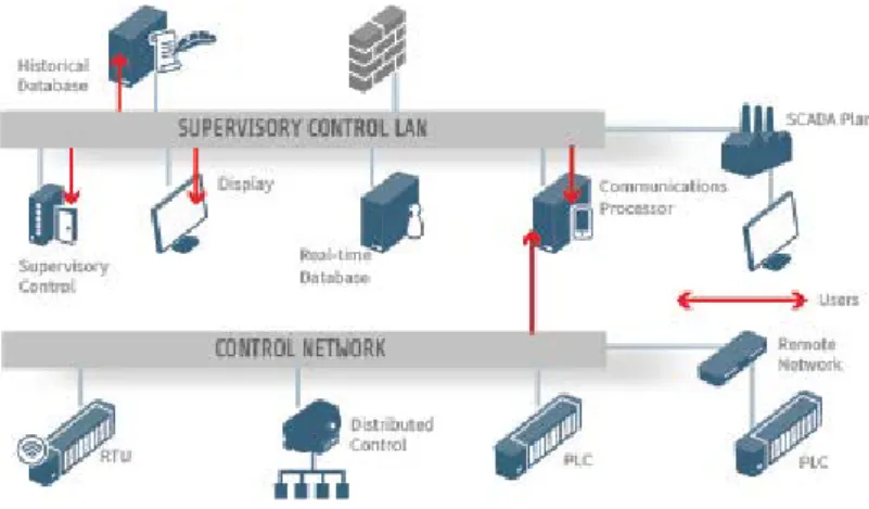
Figure 3 - a typical SCADA/ICS system
In the figures - also connected to the WAN/LAN - a web server and replicated database is located. The web server may be an externally facing web server for the company or may be a web server displaying information retrieved from the SCADA/ICS system. The implication of the existence of a web server is that there is some form of browser that is using it and that HTTP and HTTPS protocols are being used. The use of browsers introduces a range of security risks and issues.
Between the WAN/LAN, and the SCADA/ICS and its LAN, a ‘cloud’ connection is indicated in the figures. This cloud represents the fact that the SCADA/ICS system and business operations may or may not be co-located. Since the connectivity between the two is remote, either across the Internet or using M2M or other services across a number of potential communication bearers, a firewall is shown, which is being used to protect the SCADA/ICS system from remote access threats. However, it is not unusual for equipment vendors to provide network connectivity either directly using mobile phone M2M connections or connection through the Internet to their devices for patch updates, management and equipment status purposes. It is clear that in some cases engineering teams operating such equipment may be unaware of these connections, with the insight that it is not unusual for the engineering team to state that their system is secure because it is ‘air-gapped’ but when asked how they do their system management, they state that the equipment vendors remotely update and manage the systems for them. Similarly, few people realise that SAP implementation in the BSS, for example, typically has remote web access and connections back to the SAP provider in order for them to provide support and patch updates. These remote connections are typical vectors used in attacks against SCADA/ICS systems.
3 There are four ‘flavours’ or the OPC; the legacy Windows DCOM based protocol (OPC-DA), the extensions of OPC-DA to cover historians
(OPC-HDA) and Alarms and Events (OPC-AE), and a recent attempt to move OPC away from Windows reliance by using more generic SOAP/XML protocols (OPC-UA) which is described in standard IEC 62541.
Supervisory Control Implementation
The Supervisory Control system in the context shown in Figure 2 represents a small control system, perhaps in a factory or other plant. It is connected via a Communications processor to the control network, which may use the MODBUS/TCP4 protocol in industrial systems, BACNet/IP5 protocol in building management systems, LonWorks6 protocol in transport and building systems, DNP3 and IEC 60870-1047protocols in electrical systems, or other open or proprietary protocols and fieldbuses. In the general case, the control networks are typically IP protocol based (except in some legacy systems) in order to take advantage of modern ubiquitous LAN & WAN equipment and connectivity and are used for control and status of end effectors (motors and valves, for example) and sensors. For historic, and cost reasons it is unusual for motors, valves and in particular sensors to have direct IP connections, favouring serial Modbus RTU or similar standards. This is changing with the move towards ‘digital oilfields’ for example: resulting in 2-Wire and 4-Wire Modbus becoming legacy in some systems.
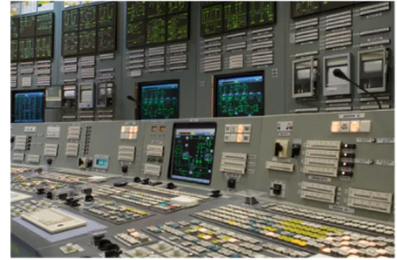
Supervisory Control has typically been implemented on Windows machines with GUIs and HMIs implemented as custom Windows or .NET mimics (Figure 4) and/or web browsers (some PLCs run WinCC controlled via local or supervisory mimics on web browsers, for example). Until very recently security of these GUIs and HMIs has been very lax leading to a frantic race to retrofit and install security capability to prevent attacks or illegal access. Typical examples of such high risk systems can be found by using the search term ‘scada’ on the Shodan search engine found on the Internet, for example.
As noted previously, data is captured, trends identified and audit information stored on the data historians (historical database in Figure 2). The main protocol used for data historians is OPC-HDA. However, it should be noted that there are typically bespoke messages and features in addition to this standard.
Some SCADA/ICS implementations contain a real-time database, which maintains state across the system and can be used for coordinated action across the underlying effectors and sensors. Propriety Distributed Control Systems (DCSs) often use a distributed control database in order to reduce the dependence on the control networks and increase reliance, should a network disruption occur a degree of operation in isolation by each control node is allowed (control island mode).
4 Modbus specifications for Modbus over Serial and Modbus/TCP are held by the Modbus Organisation
http://www.modbus.org/specs.php. See also IEEE 1711
5 BACNet and BACNet/IP are defined in ASHRAE/ANSI Standard 135 in 1995 and ISO 16484-5-2003
6 LonWorks is defined in ANSI/CEA-709.1-B and ISO/IEC 14908-1, and is used as a basis for IEEE 1473-L (in-train controls) and EN 14908
(European building automation standard)
7 DNP3 is defined in IEEE Std 1815, see also IEC 62351-5 and IEEE 1379 Figure 4 – Example of a SCADA/ICS mimic panel
Programmable Logic Controllers (PLCs) and Related Equipments
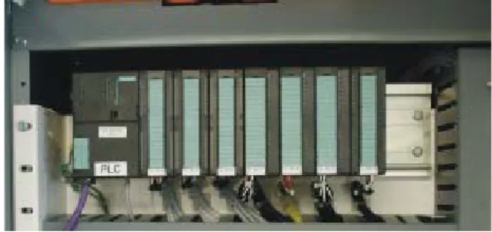
The last item shown on the Supervisory Control LAN is a communications processor. This provides the connectivity that creates the overall Control Network which links Supervisory control with multiple controllers – PLCs (Programmable Logic Controller) (Figure 5), DCSs (Distributed Control Systems – used to provide hundreds of control loop connections to the PLC), RTUs (Remote Terminal Units – essentially these are PLCs focussed on telemetry functions) and so on – at multiple positions, typically at multiple sites. Typically PLCs, DCSs, RTUs and Intelligent Electronic Devices (IEDs) run Windows based or related operating systems, such as WinCC with some older systems running or VxWorks. Some standardisation of control software language was introduced with EIC61131, although most manufacturers retain some unique characteristics not covered by the standard.
The communications that form the control network may or may not be homogeneous and typically include a mix of technologies from mobile phone M2M systems, through WiMAX and Zigbee, through to satellite. Typical sizes of such systems are one or two PLCs and a local supervisory control system with flat-panel mimic on the machine itself for CAD/CAM installations or robotic manufacturing cells, through to several hundred controllers across the factory plant covering everything from conveyors to heavy machinery, through to several thousand remote sites for water management or electrical management systems, through to thousands of nodes for large oil and gas installations and pipelines in multiple geographic regions of the world.
Summary
With connectivity to the Internet, and business systems using typical IT equipments, the majority of the attack vectors and attendant risks at the business level can be mitigated using standard IT countermeasures. However, at the supervisory layers and plant control the protocols are specific to the Industrial Control market and are not well protected by IT equipments. OPC is a good example of this, where it requires ‘holes’ to be left in the firewall via the security policy in order for it to operate. Allowing these ‘holes’ introduces a large security risk into the system. Further
into the plant equipments, multiple protocols operate simultaneously – everything from MODBUS through to OPC-HA, and HTTP through to file transfers. Supporting these protocols with firewalls is difficult and expensive because of the complexity of the zoning.
At IGUANA Security we take an alternative approach which uses a solution based on our legacy of high security products. Using the IGUANABlue Data Guard to protect individual equipments at the plant level through to the business systems
Figure 5 – Example Programmable Logic Controller (PLC) mounted in a rack
Figure 6 – IGUANABlue Data Guard for DIN-rail and plant applications
level is a cost effective solution to securing SCADA and ICS systems, particularly those in Critical National Infrastructure (CNI) applications.
At the plant level, a DIN rail, or ‘flat-back’ mountable unit provides ‘zero touch’ security of plant ICS protocols (Figure 6).
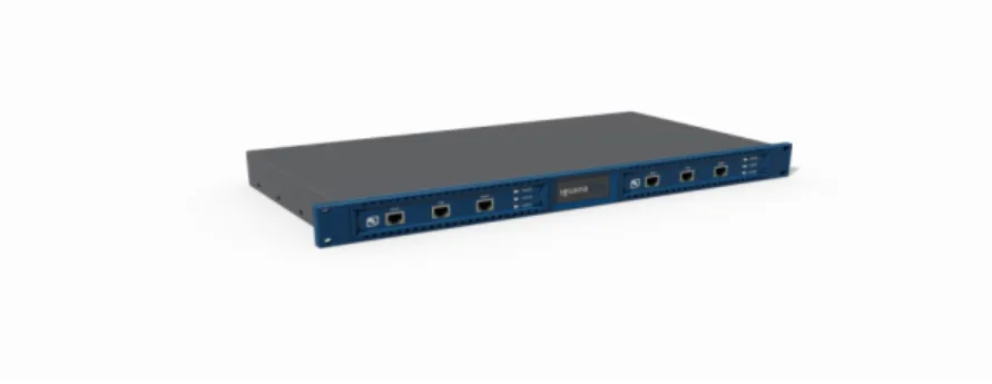
Figure 7 – IGUANABlue High Availability CNI Data Guard: 19” rack mount variant
For more information on these products, please contact IGUANA Security: IGUANA Security
Sigma Close, Tewkesbury, Gloucestershire, GL20 8ND, UK +44 (0) 1684 212447
www.iguanasecurity.com [email protected]