Email: [email protected], [email protected], [email protected]
Received July 17th, 2013; revised August 15th, 2013; accepted September 11th, 2013
Copyright © 2013 Pedro J. Castro et al. This is an open access article distributed under the Creative Commons Attribution License, which permits unrestricted use, distribution, and reproduction in any medium, provided the original work is properly cited.
ABSTRACT
Metamaterial one-dimensional periodic structures are composed of split-ring resonators, which can display electric per- mittivity and magnetic permeability simultaneously negative, are studied experimentally. In the present study, each resonator is made up of two concentric circular copper rings patterned on a substrate of kapton, with slits diametrically opposite each other and with the line of the splits along the longitudinal direction of the periodic array containing seven split rings evenly spaced. The experiments consist in inserting the metamaterial slab into a square waveguide of side length 6 mm, corresponding to a cutoff frequency of 25 GHz. Transmission bands due to magnetic and electrical re- sponses are identified for slits with aperture widths of 1 mm and 2 mm, centered at 5.67 and 6.12 GHz frequencies, re- spectively, values well below the 25 GHz frequency cutoff, so characterizing a medium with negative permeability and permittivity.
Keywords: Metamaterials; Split-Ring Resonators; Magnetic Response; Electric Response; Left-Handed Transmission Band
1. Introduction
Metamaterials are artificially structured materials espe- cially constructed to interact with electromagnetic waves so as to control their propagation characteristics. Usually incorporating concentric split-ring resonators (SRR), such materials can exhibit electric permittivity and mag- netic permeability both simultaneously negative due to the electric and magnetic responses to an incident elec- tromagnetic wave. Magnetic resonance is induced by the slits and by the separation region between the inner and outer rings, which behave as capacitive elements. Owing to the resonant behavior of the rings, such a structure can support wavelengths much larger than the dimension of the rings. According to the peculiar properties of circuits made of metamaterials, a periodic structure formed by concentric rings can be used to allow wave propagation inside miniaturized waveguide operating below cutoff [1,2]. Even smaller than the operation wavelength these structures find applications in frequency ranges spanning from microwave up to terahertz frequencies [3], as sub- wavelength waveguides and resonators, filters and delay lines. Several aspects of metamaterials research and pro- gress in this area have been reported in the literature
[4-16]. The experiments presented here concern micro- wave propagation through a waveguide loaded by arrays of seven split-ring resonators. Measured spectra show their inherent transmission characteristic and how closed rings and split rings of widths of 1 mm and 2 mm are re- lated to the magnetic and electric resonances.
2. Split-Ring Resonator Design and
Construction
Figure 1. Schematics of the split-ring resonator (design pa- rameters: d = 0.3 mm, w = 0.4 mm, t = 1.6 mm, r = 1.4 mm, a = 10.2 mm, dielectric constant of the substrate = 3.2, and g = 0, g = 1.0 mm, g = 2.0 mm).
the equivalent circuit shown in Figure 2, where L is the mutual inductance of the rings and Cg, the capacitance of the slit (gap) between the edges of rings, such that the resonance frequency can be estimated by [1] :
0
0 g 2
C C L
(1)
As mentioned earlier, the structure under study con- sists of two concentric rings with diametrically opposite splits. The magnetic response is induced through these splits which provide a negative permeability [4]. Electric resonance also occurs for the charge distribution associ- ated with the induced electric dipoles [14].
3. Experimental Arrangements and
Experiments
Figure 3 depicts three different ring arrays with seven cells used in this work: cells with closed rings, i.e., g = 0, an array with g = 1 mm, and the third one with g = 2 mm. Experiments were implemented by loading a metallic square waveguide with a periodic array of split-ring reso- nators (Figure 4). The array is placed on the plane of symmetry of a square waveguide with 6 mm side, with a corresponding cut-off frequency of 25 GHz for the dominant mode TE10. As can be seen in Figure 4, the first and the last cells of the array were placed partially out of the waveguide to strengthen its excitation. The whole experimental setup is shown in Figure 5, where the loaded waveguide is symmetrically connected at both ends to identical J-band coaxial cable adapters, used to excite and detect the propagating signal through the combined medium, i.e., metamaterial slab and waveguide. An Agilent N5230C vector network analyzer was used to measure the transmission coefficient S21 through the
Figure 2. Two-port equivalent network of the SRR unit and the corresponding transmittance spectrum.
Figure 3. Arrays of concentric rings with closed rings g = 0, and slits g = 1.0 mm, g = 2.0 mm.
Figure 4. Waveguide loaded with split-ring resonator.
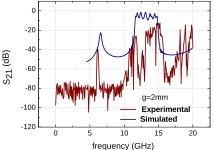
respectively, which correspond to the magnetic response of the split rings [1,2]. These values are well below the frequency cutoff at 25 GHz, thus featuring a medium with negative permeability and permittivity. Simulation results from the software CST Microwave Studio are compared with the experimentally measured transmission coefficients. A second band corresponding to the elec- trical response is most clearly observed in the simulated curves. For the array with slit width g = 1.0 mm a narrow magnetic passband is absolutely coincident with the si- mulated curve. For the slit with g = 2.0 mm, experiments confirm that the electric and the magnetic bands are both blue shifted with respect to the spectrum of the 1-mm- gap array (Figure 6). The resonator with larger slit has a higher resonance frequency because the wider the gap between the ring ends, the lower the gap capacitance and the lower mutual inductance, which in turn, according to Equation (1), both increase the resonance frequency. More- over, as the spacing d between the rings remains fixed, varying the slit width barely affects the mutual capa- citance.
Figure 8 compares the simulated (blue curve) and measured transmission coefficient S21 (red curve) for the periodic structure with closed rings (CRRs (g = 0)).
Note that for g = 0, the simulated results predict with great accuracy the location and width of the electric band (~10.9 - 14.0 GHz) with respect to the experimental curve. The presence of seven peaks in the electrical band, which corresponds to the seven resonant coupled rings, can be clearly observed. As was expected, the magnetic response signal does not appear, thus confirming that the magnetic response occurs solely with split rings. There- fore, closing the split rings no current flows across the annular gap separating the inner and outer rings and, in this way, the magnetic resonance does not arise.
To point out the transmisson band characteristics around 5.67 and 6.12 GHz, Figures 9 and 10 display, respectively, the transmission phase plot for the periodic arrays here investigated. We see that the transmission passband (with both negative permittivity and permeabi- lity) extend from 5.46 to 6.96 GHz and from 5.90 to 6.40 GHz, respectively, for the cases when g = 1.0 mm and g = 2.0 mm, thus covering a band of about 0.40 GHz in both cases (Figures 9(a) and 10(a)). We also note that the transmission band correlates with phase compression as shown in Figures 9(b) and 10(b), which can be inter-
0 5 10 15 20
-120
-100 Experimental Simulated
frequency (GHz)
Figure 6. Magnitude of the transmission coefficient S21 (dB) for the periodic structure with seven SRRs, with g = 1.0 mm, immersed in the waveguide. The blue curve shows the simu- lated coefficient while the red curve is the one measured ex- perimentally.
0 5 10 15 20
-120 -100 -80 -60 -40 -20 0
S2
1
(
d
B
)
frequency (GHz)
Experimental Simulated
[image:3.595.321.524.486.648.2]g=2mm
Figure 7. The same as in Figure 6 but with g = 2.0 mm.
Figure 8. The same as in Figure 6 but with g = 0.
preted as the signature of simultaneously negative per- mittivity and permeability. In fact, within the transmision band the slope of the unwrapped phase curve is higher than the slopes of the straight segments (Figures 9(c) and
Figure 9. (a) Measured magnitude and phase [(b) wrapped and (c) unwrapped] of the transmission coefficient S21 cor- responding to the magnetic response of the SRR with g = 1.0 mm.
Figure 10. (a) Measured magnitude and phase [(b) wrapped and (c) unwrapped] of the transmission coefficient S21 cor- responding to the magnetic response of the SRR with g = 2.0 mm.
5. Conclusion
A study of periodic arrays consisting of an array of split- ring resonators immersed in a waveguide below cutoff was performed experimentally, whereby magnetic and electric transmission bands were determined. Experimen- tal features are similar to those obtained from electro- magnetic simulation, with magnetic response peaks being almost coincident. Analyzing the behavior of structures without slits, it was verified that such resonators do not originate magnetic responses, thus demonstrating that the separation of the rings is determinant to the magnetic response. Such structures allow for the miniaturization of devices, and in the present work, the diameter of the rings is much smaller than the operating wavelengths of magnetic response, a ratio of about 1/10. The observed slopes in all cases concerning unwrapped phases along the transmission magnetic band can be interpreted as an evidence of simultaneously negative permittivity and permeability of the combined medium.
6. Acknowledgements
This work has been supported by FAPESP (São Paulo Research Foundation) and CNPq (National Council for Scientific and Technological Development) in Brazil.
REFERENCES
[1] J. J. Barroso, P. J. Castro and J. P. Leite Neto, “Experi- ments on Wave Propagation at 6.0 GHz in a Left-Handed Waveguide,” Microwave and Optical Technology Letters, Vol. 52, No. 10, 2010, pp. 2175-2178.
doi:10.1002/mop.25435
[2] R. Marqués, J. Martel, F. Mesa and F. Medina, “Left- Handed-Media Simulation and Transmission of EM Waves in Subwavelength Split-Ring-Resonator-Loaded Metallic Waveguides”, Physical Review Letters, Vol. 89, No. 18, 2002, pp. 183901-183904.
doi:10.1103/PhysRevLett.89.183901
[3] H. O. Moser, B. D. F. Case, O. Wilhelm and B. T. Saw, “Terahertz Response of a Microfabricated Rod-Split- Split-Ring-Resonator Electromagnetic Material,” Physi- cal Review Letters, Vol. 94, No. 6, 2005, pp. 063901- 063904. doi:10.1103/PhysRevLett.94.063901
[4] J. B. Pendry, A. J. Holden, D. J. Robbins and W. J. Stew- art, “Magnetism from Conductors and Enhanced Nonlin- ear Phenomena,” IEEE Transactions on Microwave The- ory and Tecnique, Vol. 47, No. 11, 1999, pp. 2075-2084. doi:10.1109/22.798002
[5] W. C. Chew, “Some Reflections on Double Negative Ma- terials,” Progress in Electromagnetics Research, Vol. 51, No. 1, 2005, pp. 1-26. doi:10.2528/PIER04032602
[6] J. Pendry, “Manipulating the Near Field with Metamateri- als,” Optics and Photonic News, Vol. 15, No. 9, 2004, pp. 32-37. doi:10.1364/OPN.15.9.000032
[image:4.595.75.271.83.356.2] [image:4.595.74.272.419.689.2][10]D. R. Smith, W. J. Padilla, D. C. Vier, S. C. Nemat-Nas- ser and S. Schultz, “Composite Medium with Simultane- ously Negative Permeability and Permittivity,” Physical Review Letters, Vol. 84, No. 18, 2000, pp. 4184-4187. doi:10.1103/PhysRevLett.84.4184
[11]K. Aydin and E. Ozbay, “Identifying Magnetic Response of Split-Ring Resonators at Microwave Frequencies,” Opto-Electronics Review, Vol. 14, No. 3, 2006, pp. 193- 199. doi:10.2478/s11772-006-0025-x
[12]K. Aydin, I. Bulu, K. Guven, M. Kafesaki, C. M. Sou- koulis and E. Ozbay. “Investigation of Magnetic Reso- nances for Different Split-Ring Resonators Parameters and Designs,” New Journal of Physics, Vol. 7, No. 168,
[15]K. Aydin, K. Guven, M. Kafesaki, L. Zhang, C. Soukoulis, E. Ozbay, “Experimental Observation of True Left-Hand- ed Transmission Peaks in Metamaterials,” Optics Letters, Vol. 29, No. 22, 2004, pp. 2623-2625.
doi:10.1364/OL.29.002623
![Figure 9. (a) Measured magnitude and phase [(b) wrapped and (c) unwrapped] of the transmission coefficient Sresponding to the magnetic response of the SRR with g = 1.0 mm](https://thumb-us.123doks.com/thumbv2/123dok_us/7863372.737380/4.595.74.272.419.689/measured-magnitude-unwrapped-transmission-coefficient-sresponding-magnetic-response.webp)
