Development of DC-AC Link Converter for
Wind Generator
A.Z. Ahmad Firdaus*, Riza Muhida*, Ahmed M. Tahir*, A.Z.Ahmad Mujahid**
* Department of Mechatronics Engineering, International Islamic University Malaysia, Gombak, Kuala Lumpur,
Malaysia. Email: [email protected]
** Department of Mechanics, Faculty of Mechanical and Manufacturing Engineering, University of Tun Hussein Onn
Malaysia, Parit Raja, Malaysia. Email: [email protected]
Abstract— The usage of wind power as alternative source of
energy in Malaysia is very scarce and perhaps limited to several private establishments. There is urgent need to locally develop the low cost wind turbine generator that has the capability to not only supply electricity to respective household but can be connected to power grid so that excess power could be sold back to the local utility company. Recent developments of power electronic converters allow stable supply needed for grid transfer in respect to nature of wind dynamics, enhanced power extraction and low total harmonic distortion (THD). In this project, an inverter circuit with suitable control scheme design is developed to be used with a wind turbine generator. From DC output of the generator, the DC-DC boost converter will step up the voltage to a nominal DC voltage at the grid. The inverter then will turn the voltage to sinusoidal AC to be transferred at grid. The duty cycle of signal controlling MOSFET transistors in the inverter will be controlled voltage source Pulse-Width Modulated (PWM) signal generated by microcontroller PIC16F877A based on pure sine wave data stored in the microcontroller memory. The lab-scale experimental rig involves simulation wind speed by running geared DC motor coupled with 500W wind generator where the prototype circuit will be connected at generator output. Expected circuit output is single phase 240V sine wave voltage which is nominal grid voltage. The next phase of the rig will involve testing the prototype circuit with site installed 500W wind generator. The necessary performance parameter will be evaluated.
Keywords—microcontroller, inverter, buck converter, boost
converter, grid, PWM, THD.
I. INTRODUCTION
In the beginning, scope of energy supply from alternative sources is limited to remote and isolated area, i.e not accessible to utility grids. Ever since, several techniques to connect alternative source (from wind, solar or hybrid of both) of energy to the supply grid has been developed and proposed by [2-5]. While grid-connecting capability is said to be more practical and economical when supply taken from wind farms, manufacturing plants, involving MW scale, supply from residential housing should also be considered in order to increase energy efficiency. Through proper planning, small scale wind generator can be installed to each individual
housing units of a residential park. This way the usage of electricity supplied from utility company can be reduced during windy times and excess energy generated can be re-supply back to utility company through the grid [3]. Inverter circuit with suitable control scheme must be incorporated in the system to supply AC voltage for domestic use as well as to enable power resupply back to the grid.
Due to varying nature of wind, the designed system must be able to operate under various wind speed condition while maintaining optimum power supply, maintaining constant voltage and frequency [4]. Need to develop simple working inverter control circuit that takes DC input from Wind Turbine Induction Generator and can transfer energy to the grid. For prototype, the inverter should be able to work with 500W Wind Turbine and supply 240V single phase AC to grid. The quality of power supply also must have high power factor particularly when dealing with high load, and low total harmonic distortion (THD), preferably below 3%.
II. THEORITICAL CONSIDERATION
A. Wind Power Consideration
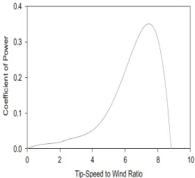
Total rotational power captured by wind energy system is given by formula [2]:
A v AC
Pt P W3
2
1
ρ
= (1)
Where
ρ
is Air density (kg.m-3), Wv is Wind speed (m/s), CP is Coefficient of performance, and A is Rotor rotational area (m2).
Figure 1: Relationship of TSR and Cp
TSR is calculated by formula below [2]:
W
v r
TSR =
ω
(2)Where vW is Wind speed (m/s),
ω
is Turbine rotational speed, (rad/sec),r
is Turbine rotor radius (m). [image:2.595.303.539.186.472.2]The dynamic nature of wind speed will cause small variations of voltage, current and power generated under normal operating condition. Figure 2 [7] shows the wind generator manufacturer performance datasheet on voltage generated at various wind speed.
Figure 2: 500W Wind Generator Manufacturer Performance Datasheet
[image:2.595.56.289.393.572.2]B. Principle of Boost (Step-up)DC-DC Converter
Figure 3: Boost converter schematic
Figure 3 [6] above is the basic schematic circuit of boost DC-DC converter. The basic principle of step-up (boost) DC-DC converter is as follows. When switch SW is closed for the time t1, inductor current rises and energy
is stored in inductor L. If switch is opened for time t2, energy stored in the inductor is transferred to load through diode D1 and the inductor current falls. For a continuous current flow, waveform for the inductor current is as in figure. If large capacitor C is connected across the load, output voltage is continuous and becomes average value. Voltage across the load can be stepped up by varying duty cycle and the minimum output voltage is Vi when k = 0 [6].
The average output voltage is [6]
k
V
t
t
V
t
I
L
V
V
o i i i−
=
+
=
∆
+
=
1
1
)
1
(
2 1
2
(3)
For a resistive load, ripple current is given by [6]
kT
L
V
I
=
i∆
(4)C. Principle of H-Bridge Circuit
Figure 4: Standard H-Bridge circuit
In Figure 4 [3,6] a standard H-Bridge configuration is presented. 4 switches A1, A2, B1 and B2 are arranged in this configuration. Input to the circuit VCC which is DC voltage. Output of the circuit is positive and negative pulse voltage measured across the load. The load voltage varies accordingly and is in the range of +VCC and – VCC. Bipolar mode switching technique has to be implemented to achieve the required output. This means that the inputs of switches A1 and A2 are switched simultaneously at one half while the switches B1 and B2 are simultaneously switched at the other half. In circuits the switch is represented by MOSFET transistors.
An inverter control circuit must be included in the design to control the switching of the H-bridge gates. Usually a microcontroller is used to perform the job due to capability to sense signals and generate trigger signals, performing comparator function, among others [3,6,8].
III. METHODOLOGY
[image:2.595.101.259.627.711.2]DC-AC inverter circuit and simulate performance of the inverter circuit to obtain desired voltage output of 240V, 50Hz where the scope of system design consists of:
o Design of bridge rectifier at generator output.
o Design of suitable boost DC-DC converter to step up from low wind voltage.
o Design of H-bridge circuit to output AC from DC.
o Design of microcontroller circuit and programming software to control duty cycle of H-bridge circuit.
o To test the inverter circuit in lab-scale with Wind Generator to get experimental performance data.
[image:3.595.309.534.281.469.2]o To test the performance of inverter circuit with site-installed Wind Generator to get experimental performance data. Refer Figure 4 for actual permanent magnet synchronous generator manufacturer performance datasheet.
Figure 5: Block diagram of proposed system
A. Bridge Rectifier Circuit Design
The voltage generated at terminal by wind generator will be AC waveform type of magnitude 10V to 30V depending on the wind speed. Figure 2 [7] shows the wind generator manufacturer performance datasheet on voltage generated at various wind speed. A bridge rectifier circuit is connected at wind generator terminal to convert the waveform to DC. Figure 6 below shows the bridge rectifier circuit design.
D 1 D 1 N 4 1 4 8
D 2 D 1 N 4 1 4 8 D 3
D 1 N 4 1 4 8 D 4 D 1 N 4 1 4 8
C 1 4 7 0 0 u
1 0 0 V
W i n d g e n e r a t o r
1 8 V a c 0 V d c
0
[image:3.595.64.282.303.480.2]D C O u t p u t
Figure 6: Bridge rectifier circuit
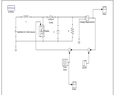
B. Boost DC-DC Converter Design
The DC output voltage from the rectifier circuit is in relatively small amplitude compared to standard nominal single phase voltage rating for use with domestic household products or to be transferred at grid [3,7]. The dynamic nature of wind speed will cause small variations of voltage generated under normal operating condition. The boosts DC-DC converter circuit will step-up the unregulated DC voltage to 240V DC regulated [6]. In this design the output of the converter is feedback and compared to set value equivalent to 240V. Then the carrier signal will be compared with the error signal to generate PWM signal. The duty cycle of PWM signal, k is determined by error gap between circuit output and setpoint. Output voltage is stabilized and regulated by minimizing ripple output voltage and current. The value of L and C is determined by formula related with (4).
Figure 7: Design of Boost DC-DC converter in SIMULINK
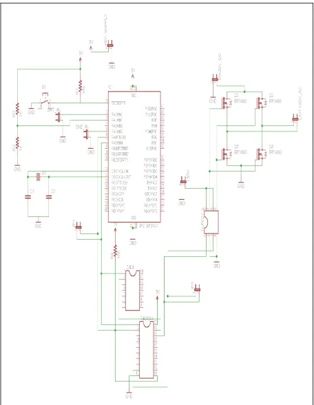
C. Design of Inverter Control Circuit
Figure 8 below shows the proposed inverter control circuit comprising the H-bridge circuit and the control circuitry.
The type of inverter implemented in the system is voltage-source-inverter (VSI) and the control technique implemented in the system is Sinusoidal pulse-width modulation (SPWM) [6]. Using this technique, the microcontroller PIC 16F877A is used to generate the required PWM train of pulses to drive and switch on the H-bridge MOSFET transistors.
[image:3.595.62.287.612.742.2]Transciever. The output is two channels of PWM train pulse switching ON and OFF at 180 degree out of phase. The two signals are then connected to necessary conditioning elements to be able to switch ON the MOSFET transistors at the H-bridge. Now the generated PWM will switch two diagonal MOSFET transistors of the H-bridge simultaneously at one of the two halves and the other two diagonal transistors at the other half. The output of H-bridge is connected the load through LC filtering to achieve desired AC sinusoidal waveform.
Figure 8 Inverter Control Circuit
D. Experimental Rig and Hardware Setup
In the lab-scale experimental rig, a 300W geared DC motor will be coupled with wind generator through an inertia disk to simulate wind speed and wind blade rotor. Bridge rectifier is connected after wind generator to feed DC voltage to the inverter control circuit as the output is AC. The output of inverter will be connected to either dump load or grid. The DC motor will be programmed to run at various speed to simulate variability of wind speed while necessary performance parameter will be evaluated.
At the next stage, the wind generator will be erected at proper site where the generator output will be connected to the system and necessary performance parameter will be evaluated.
Figure 9: Proposed Lab-scale experimental rig
IV. ANALYSISAND RESULTS
A. Simulation Results
[image:4.595.59.287.196.490.2]The DC/DC boost converter and H-bridge was simulated in SIMULINK environment to get the general output.
[image:4.595.309.537.349.510.2]Figure.10: Simulated output of Boost DC-DC Converter
[image:4.595.319.524.523.697.2]Figure 12: Simulated response H-bridge circuit
B. Experiemental Results
[image:5.595.65.284.72.188.2]Figure 13: Sine wave generated by microcontroller PIC16F877A
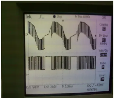
[image:5.595.62.283.245.391.2]Fig.14: Trigger SPWM signals to the H-bridge gates
Fig.15: Voltage output of the half bridge of the H-bridge shown in channel 2 of the oscilloscope
V. CONCLUSION
Based on experimental results, research objective to generate 240V AC waveform at 50Hz frequency has been partially achieved. The output waveform has been generated through half bridge and has yet to be successfully implemented in full H-bridge circuit. The waveform could be improved further with improvisation of PWM signal and inclusion of proper filtering elements in circuit design.
REFERENCES
[1] Mihet-Popa, L.; Blaabjerg, F.; Boldea, I., "Wind Turbine Generator Modeling and Simulation where rotational speed is the controlled variable," Industry Applications, IEEE Transactions on , vol.40, no.1, pp. 3-10, Jan.-Feb. 2004
[2] Arifujjaman, Md.; Iqbal, M.T.; Quaicoe, J.E., "Maximum Power Extraction from a Small Wind Turbine Emulator using a DC - DC Converter Controlled by a Microcontroller," Electrical and Computer Engineering, 2006. ICECE '06. International
Conference on , vol., no., pp.213-216, 19-21 Dec. 2006
[3] Beck, Y.; Bishara, B.; Medini, D., "Connecting an alternative energy source to the power grid by a DSP controlled DC/AC inverter," Power Engineering Society Inaugural Conference and
Exposition in Africa, 2005 IEEE , vol., no., pp. 120-124, July
11-15, 2005
[4] Jamal A. Baroudi, Venkata Dinavahi, Andrew M. Knight, A review of power converter topologies for wind generators, Renewable Energy Volume 32, Issue 14, , November 2007, Pages 2369-2385
[5] Ning Zhu, Hui Liang, Implemetation and Control of Dual Grid Connected Inverter for Wind Energy Conversion System,"
Industry Applications, IEEE Transactions on , vol.40, no.1, pp.
3-10, Jan.-Feb. 2006
[6] Muhammad H. Rashid, Power electronics: circuits, devices, and
applications, 3rd Ed., 2004, Pearson/Prentice Hall.
[7] Hummer 500W Wind Turbine Operation Manual by Anhui Hummer Dynamo Co. Ltd
[image:5.595.57.288.423.612.2]