Analysis on Effect of Parameters of Different Wind
Generator on Power Grid Transient Stability
*
Zhi-wei Wen1, Li Ding 2, Shi-en He3 1Gansu Electric Power Research Institute, Lanzhou, China
2Beijing Electric Research Institute of Economics and Technology, Beijing, China 3Wind Power Technology Center of Gansu Electric Power Corporation, Lanzhou, China
Email: [email protected]
Received January, 2013
ABSTRACT
To analyze the factors which affecting transient stability of power system, the dynamic model of doubly-fed induction generator and direct-drive PM synchronous generator has been built using PSCAD. Impact of different wind farm inte-gration on grid typically in China has been presented. The influence of the variations of transient reactance, negative sequence reactance and rotary inertia on critical clearing time of power system transient stability is analyzed by time-domain simulation. Mixture operation of DFIG and PMSG to optimize the stability of system has been analyzed firstly. The digital simulation results show that doubly-fed induction wind turbines is a better choice to meet the re-quirement of system instability due to large wind farm integration in comparison with direct-drive PM synchronous wind turbines. With a rather large rotary inertia, the proper ratio of direct-drive PM synchronous wind turbines used in wind farm could be comprehensive planning by optimized the stability of system. Analysis of this paper should be pro-vided as academic reference for improving design of wind farm system.
Keywords: Wind Farm; Doubly-fed Induction Generator; Direct-drive PM Synchronous Generator; Parameter; Transient Stability
1. Introduction
Unlike coal and other conventional resources used for power generation, some renewable energy, such as wind power, is random, intermittent and uncontrollable. Acci- dent of grid or the tripping of wind farm will increase the difficulty of system recovery with significant penetration of wind power, even leading to the grid collapse. During the past decades, wind power penetration limit has been exceeded from about 5 percent to 20 percent in many countries based on the reactive power compensators and reinforcement of networks[1]. The choice of wind gen- erator has been an important technical and economic target to power system because analysis results show that parameters of induction motor, such as stator reactance, initial rotor slip, have influence on power system tran- sient stability[2]. Effect of mechanical parameters of induction generator (IG) and doubly-fed induction gen- erator (DFIG) has been analyzed in conference[3]. Com- parative analysis between IG, DFIG and direct-drive permanent magnetism synchronous generator (PMSG) on power system transient stability shows that variable speed wind generator is a better choice to meet the re-
quirement of system in stability due to large wind farm integration in comparison with wind generator of con- stant speed[4]. Because the effect of converter, it is dif- ficult to research the contrast between different type of wind generator.
The main motive of this paper is to develop a simula-tion platform of the integrated wind farm, and to evaluate the performances of the transient characteristic with dif-ferent t type of wind generator. Models of difdif-ferent type of type of wind generator connected with grid are estab-lished. Furthermore, some factors of generator which affect the permissible power flow of the grid, such as transient reactance, negative sequence reactance and ro-tary inertia, have been studied. Comparative analyze of the critical clearing time (CCT) have been proposed. Es-pecially, mixture operation of DFIG and PMSG to opti-mize the stability of system has been analyzed that can provide fundamental data for future research of the wind energy development.
2. Model of Grid
2.1. Model of Grid-connected System
To investigating the transient stability of power system connected with a large wind power, a simulation system *This work was supported by Science and Technology Research
was developed. The simulation system consists of three parts: the wind power generator, the transmission system and the consumer load.
The transmission system of HVAC is the most popular transmission system, which is shown in Figure 1. It needs support power grid and reactive power compensa-tion equipment to meet the requirement of voltage and frequency regulation[5].
2.2. Model of Grid-connected Wind Farm
A typical wind power system includes generator, three- blade rotor, gearbox, and control devices of wind speed, blade angle and voltage. Accessory system includes convertor and protection devices. DFIG is the main type of wind generator used in grid-connected wind farm be-cause of active and reactive power flow of grid can be decoupling controlled by convertor of wind farm to im-proved electric power quality and power factor of wind farm[6]. But in recent decade, more and more PMSG based on full power convert have been used in wind farms to realize the flexible control of operation[7]. On the other hand, price fluctuation of magnet material will affect the future interest of manufacture and the cost of using PMSG. Diagram of wind power system with DFIG and PMSG are shown in Figures 2 and 3, respectively.
2.3. Equivalent Circuit of Generator
Using equivalent T-circuit of DFIG, equations of static electromagnetism analysis can be described as [8]:
s s s s s r m
s r
r r s r m
U I r jx I I jx
U r
jX I I I jx
s s
(1)
where Us and Is stand for the voltage and current of the stator, respectively (p.u.); Ur and Ir stand for the voltage and current of the rotor, respectively(p.u.); s is the slip factor; rs and xs stand for the resistance of the stator and synchronizing reactor of generator, respectively (p.u.); xm stand for the field reluctance of rotor(p.u.) ; rr and xr stand for the resistance and reactor of rotor, respec-tively(p.u.).
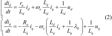
Using equivalent Γ-circuit of PMSG, equations of static electromagnetism analysis can be described as[9]:
0
1
1 1
q
d a
d e q d
d d d
q a d
q e d
q q q
L
di r
i i u
dt L L L
di R L
i i
dt L L L L
q q
u
(2)
where id and iq stand for the d-axis current and q-axis
current of stator, respectively(p.u.); Ld and Lq stand for
the d-axis induction and q-axis induction of stator, re-spectively(p.u.); ra stand for the resistance of the stator;
ωe stand for the angular frequency; λ0 stand for the
mag-netic flux linkage; ud and uq stand for the d-axis voltage
and q-axis voltage of stator, respectively(p.u.).
Figure1. Model of transmission system based on HVAC.
Figure 2. Model of wind turbine with DFIG.
[image:2.595.349.539.212.274.2]2.4. Model of Wind Farm and Stability Limit of Power System with Multi Generators
In most conference, we always assume a wind farm con-nected with the grid as an equivalent generator to simpli-fied exponent number of model of wind farm. To analyze power distribution and interrelationship of different type of generator, a mixture operation model of wind farm with DFIG and PMSG has been discussed in this paper.
Transient stable region of power system with multi generators defined as[10]:
A(Tm)={(ω1, ω2,…, ωm)|-Tei(ω1, ω2,…, ωm)>-Tmi,
i=1,2,…m} (3) where A is stable region of power system operated on balance point after the fault; Tmi is the input mechanical
torque of the ith generator; Tei is the electromagnetic
torque of the ith generator.
To analyze the stability limit of power system with multi generators, such as calculating the critical clearing time (CCT), the CCT of power system is the time when any one of generators could not meet the requirement of equation (3).
3. Simulation
3.1. Diagram of Power System
A typical single-load infinite-bus power system connected
with a group of wind farm been built using PSCAD is shown in Figure 4. To analyze the effect to the transient stability of grid, only value of one parameter of generator in the wind farm G1, such as transient reactance, would be changed linearly to calculate the CCT of power sys-tem when two-phase short circuit fault occurred in one transmission line. The voltage of load, transmission power and other parameters of grid will keep constant.
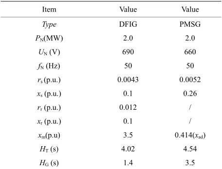
Parameters of two typical wind generators used in wind farm are shown in Table 1.
3.2. Result of Simulation
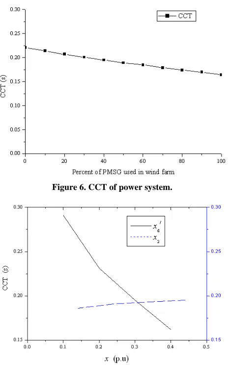
Firstly, the ratio of PMSG used in the wind farm G1 would be changed linearly to analyze the effect of mix-ture operation. Results of simulation shown in Figure 5 are that value of initial power-angle get smaller with the increasing the ratio of PMSG used in wind farm. It means that failure recovery procedure of power system be different with different wind generator used in the same wind farm. Neglecting the effect of control strategy, the CCT also get smaller is shown in Figure 6. It means that transient stability of power system maybe get worse whit more PMSG connected with grid.
As we all know, there are two main factors of genera-tor used in wind farm that affect the transient stability of grid: main electric parameters and mechanical parame-ters.
M
240 MW 10.5 kV cosφ=0.80
300 MVA 10.5/242 kV
Uk%=14%
280 MVA 220/121 kV
Uk%=14%
Y0 Y0
G1 T-1 L T-2
115 kV P0=220 MW
cosφ=0.98
[image:3.595.61.498.430.518.2]230 km
[image:3.595.306.538.543.721.2]Figure 4. Diagram of single-load infinite-bus power system. Table 1. Parameters of a wind power generator system.
Item Value Value
Type DFIG PMSG
PN(MW) 2.0 2.0
UN (V) 690 660
fN (Hz) 50 50
rs (p.u.) 0.0043 0.0052
xs (p.u.) 0.1 0.26
rr (p.u.) 0.012 /
xr (p.u.) 0.1 /
xm(p.u) 3.5 0.414(xad)
HT (s) 4.02 4.54
[image:3.595.58.286.562.736.2]Figure 6. CCT of power system.
Figure 7. Curve of CCT with change of reactance. Aim to analyze the effect of electric parameter, the va
riation of calculating CCT with changing rotary in
riation of calculating CCT when change transient re-actance and negative sequence rere-actance of generator is shown in Figure 7. Results of simulation show that CCT of system get smaller when increasing the transient reac-tance of wind generator. On the contrary, the calculating CCT of system get a little bigger when increasing the negative sequence reactance of wind generator. Com-parative simulation shows that the effect of transient actance is more significantly than negative sequence re-actance.
The va
ertia of generator to analyze the effect of mechanical parameter is shown in Figure 8. Results of simulation show that CCT of system get larger when increasing the transient reactance of wind generator. One reason of de-velopment of PMSG is to raising the pull-in torque of generator to improve the utilized coefficient of wind en-ergy, improving of transient stability of power system would also be ascribed to this electromagnetic and me-chanical character.
Figure 8. Curve of CCT with rotary inertia.
Results of simulation show that transient stability of po
convert in both DFIG an
4. Conclusions
lation of a grid-connected wind farm wer system would be affected by electromagnetic pa-rameters and mechanical papa-rameters of generator in a complementary way. For PMSG, on the one hand the bigger would contribute to the transient stability; On the other hand, the bigger transient reactance would worsen the transient stability of power system. Considering all these factors, the result of transient stability of power system should be as the basis of choosing the type of generator or defining the number of PMSG which has some promising features, such as high torque and low speed are desired in wind farm.
Because the power control of
d PMSG been neglected, results of simulation in this paper just revealing some possible reason based on elec-tromagnetic and mechanical parameters of generator. For further application of wind generator, a study of optimum design of generator should also be needed.
In this paper, a simu
[image:4.595.310.540.84.265.2]CES
[1] S. E. He and S. Jiale, “Vision of a Strong and Smart Grid
to Accommod uan Wind Power,”
Journal of Fif nce on Critical
Stability,” Power System Technology (in
based Embedded
REFEREN
ate the 10 GW-level Jiuq th International Confere
frastructure (CRIS 2010), Beijing, China, 2010, pp. 19-21.
[2] H. D. Sun, X. X. Zhou and R. M. Li, “Influence of Induc-tion Motor Load Parameters on Power System Transient
Voltage
Chi-nese), Vol. 29, No. 23, 2005, pp.1-6.
[3] S. K. Salman and A. L. J. Teo, “Windmill Modeling Con-sideration and Factors Influencing the Stability of a Grid-connected Wind
Power-Generator,” IEEE Transaction on Power Systems, Vol. 18, No. 2, 2003, pp. 793-803.
doi:10.1109/TPWRS.2003.811180
[4] N. Cao, Y. C. Li, H. X. Zhao, et al., “Comparison of Ef-fect of Different Wind Turbines on
Stability,” Power System Technolo
Power Grid Tra gy (in Chinese), Vol.
anent Magnetized
dy, et al., “Modeling
nsient
31, No. 9, 2007, pp. 53-57.
[5] M. Stiebler, “Wind Energy Systems for Electric Power
Generation,” Springer, 2008, ISBN: 978-3-540-68762-7. [6] N. Horle and A. Maeland, “Electrical Supply for Offshore
Installations Made Possible by Use of VSC Technology,” CIGRE 2002 Conference, Paris, 2002.
[7] K. Oystein, “Design of Large Perm
Synchronous Electric Machines,” Ph.D. Thesis, Norwe-gian University, Trondheim, 2011.
[8] Y. Z. Lei, A. Mullance, G. Lightbo
of the Wind Turbine with a Doubly Fed Induction Gen-erator for Grid Integration Studies,” IEEE Transaction on Energy Conversion, Vol. 21, No. 1, 2006, pp. 257-264.
doi:10.1109/TEC.2005.847958
[9] F. Gao, N. An, F. Su, et al., “Modelling and Operating
. Wang, “Modelling and Characteristics of Direct Drive Wind Farm Connecting to Power Grid,” Journal of International Conference on Electrical and Control Engineering (ICECE 2011), Bei-jing, China, 2011, pp. 704-708.
[10] N. C. Zhou, Q. G. Wang and P